- A 14mm porcelain panel delaminated during thermal cycling because anchor hardware was carried over from a natural stone submittal without review.
- Porcelain’s high MOR misleads specifiers because brittleness at anchor points is the real failure risk, not flexural strength.
- ASTM C1242-20 safety factors were calibrated for stone grain behavior and applying them to porcelain is a category error with serious consequences.
- Field-cut kerf slots made with stone saws routinely introduce micro-fractures that reduce pull-through capacity by 30 to 40 percent.
- No North American standard requires cyclic anchor-zone testing for porcelain panels, leaving engineers to fill the gap with inadequate stone tables.
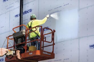
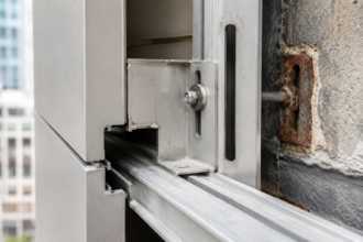
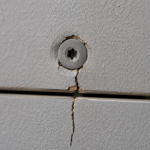
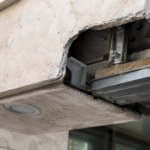
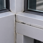
A 14mm thin porcelain slab panel on a mid-rise commercial rainscreen project in the Pacific Northwest delaminated at its kerf anchor slot during final inspection: not under wind load, but during routine thermal cycling in the first autumn after installation. The failure traced back to anchor hardware specified from the project’s original natural stone submittal, carried over without material-specific review.
That substitution decision, made to save weight and cost, exposed a gap that neither the specifier nor the facade contractor had anticipated.
Why Thin Porcelain Is Gaining Ground in Commercial Rainscreen Design
The weight argument is real and it is persuasive. Thin porcelain panels at 14 to 20mm typically weigh 28 to 35 kg/m², compared to 50 to 70 kg/m² for 30mm granite.
That delta matters at the shelf angle, at the subframe connection and in the seismic mass calculation. On a 10-story building with 2,000 square meters of cladding, switching from 30mm granite to 14mm porcelain can reduce facade dead load by 30,000 kg or more, a reduction that propagates through the structural frame design and can affect foundation sizing on marginal soil conditions.
Simplified logistics follow: large-format panels ship on standard flatbed equipment without the specialized crating that dimensional stone requires and the colorfast fired surface eliminates the sealing and maintenance cycles that stone owners eventually face. A polished granite facade in a wet coastal climate requires resealing on a 5 to 7 year cycle to maintain stain resistance and freeze-thaw performance.
Thin porcelain requires none of that and that lifecycle cost argument resonates with institutional owners managing long-term facility budgets.
Specification frequency for thin porcelain in institutional, hospitality and mixed-use facades across North America has increased measurably since approximately 2015, driven partly by manufacturer marketing that positions these panels as direct drop-in substitutes for stone in anchored rainscreen systems. That framing is commercially effective and technically dangerous.
Several major Italian and Spanish manufacturers entered the North American market during this period with large-format panels in the 1200 x 2400mm and 1500 x 3000mm range, actively targeting projects where granite or limestone had been specified in schematic design. The marketing materials emphasize MOR values, dimensional stability and low water absorption.
They do not prominently address anchor-zone fracture mechanics or the limitations of applying stone anchor design standards to ceramic products.
The substitution narrative obscures a fundamental material science difference. Porcelain is a fired ceramic with near-zero plastic deformation capacity before fracture.
Stone, for all its variability, has grain boundaries and micro-crack arrest mechanisms that distribute localized stress. Porcelain does not.
The moment you treat a porcelain panel like a granite panel at the anchor point, you have accepted a failure mode the design has not addressed.
Material Properties That Separate Porcelain From Stone and Terracotta
Thin porcelain’s modulus of rupture per ISO 10545-4 typically falls between 35 and 55 MPa. Granite runs 15 to 25 MPa and extruded terracotta 8 to 18 MPa.
Porcelain is stronger in flexure. That fact gets cited in manufacturer datasheets and it consistently misleads specifiers into underestimating brittleness risk.
Higher MOR means the panel resists bending load up to a higher threshold. It does not mean the panel tolerates anchor-point stress concentration better.
When porcelain reaches its limit, it fractures suddenly. No plastic hinge forms.
No visible deformation precedes the failure. Aluminum-backed composite panels yield progressively; stone panels crack visibly before releasing.
Porcelain panels release without warning. That distinction is not academic when panels are installed at height above a public entrance.
The fracture energy of thin porcelain is low relative to its strength, meaning the energy stored elastically at the point of failure is released almost instantaneously into crack propagation. The result is a clean, fast fracture rather than the progressive splitting that gives stone panels a visible warning period.
Kerf slot geometry sensitivity compounds the problem. Most thin porcelain manufacturers specify kerf tolerances of plus or minus 0.5mm.
Field cutting with standard stone saws routinely exceeds this tolerance and the excess introduces micro-fractures at the slot root that are invisible under visual inspection. The slot root is exactly where fracture initiates under pull-through loading.
A slot root radius of 1mm versus 0.3mm produces a meaningful difference in stress concentration factor and field cutting with incorrect tooling consistently produces the smaller, sharper root geometry. Manufacturer tolerance specifications assume shop cutting with ceramic-specific diamond blades under controlled feed rate and coolant conditions.
Those conditions are rarely replicated in field fabrication environments.
Thermal expansion differential adds another stress pathway. Porcelain expands at roughly 6 to 8 times 10 to the negative sixth per degree Celsius.
An aluminum subframe expands at approximately 23 times 10 to the negative sixth per degree Celsius. That differential is not trivial across a 1200mm panel in a climate with 40-degree seasonal swings.
The stress concentrates at the anchor contact point, cycling with every temperature change, long before any design wind event occurs. On a 1200mm panel spanning between two anchor clips, a 40-degree temperature swing produces approximately 0.9mm of differential movement between the aluminum subframe and the porcelain panel.
That movement must be accommodated at the anchor interface. If the clip geometry does not allow it, the movement transfers as a prying force into the kerf slot root.
ISO 10545-4 was developed for ceramic tile flexural strength testing. It was not developed for anchored facade panel structural design and it does not address anchor-point stress concentrations under cyclic differential movement.
How Standard Stone Anchor Design Assumptions Fail for Porcelain
ASTM C1242-20, Standard Guide for Selection, Design and Installation of Dimension Stone Attachment Systems, is the document most North American facade engineers reach for when they need anchor design guidance. Its Section 6 safety factor recommendations, typically 4:1 for granite kerf anchors, were calibrated for stone’s grain structure and micro-crack arrest behavior.
Neither property exists in porcelain. Applying C1242-20 safety factors to porcelain kerf anchor design is not conservative.
It is a category error.
The anchor pull-through failure mode in porcelain does not resemble stone. The kerf slot does not yield.
Instead, a triangular fracture cone propagates from the slot root to the panel face, releasing the panel suddenly and completely. Section 7 of C1242-20 addresses kerf anchor geometry for dimension stone; it provides no guidance for ceramic or porcelain products and its scope statement makes this explicit.
That scope limitation rarely survives the journey from specification to shop drawing review. By the time a shop drawing package reaches the facade engineer of record for review, the anchor design has typically been prepared by a subcontractor using whatever reference document is most familiar and C1242-20 is the most familiar document available.
The engineer reviewing the submittal is checking numbers against a standard that was never intended to apply to the material in front of them.
No current North American facade standard addresses point-load concentration at undercut anchor or kerf clip bearing surfaces for ceramic or porcelain panels. Engineers are defaulting to stone anchor tables without adjustment because no validated alternative exists for this continent.
The absence of a North American equivalent to Europe’s ETAG 034, the Guideline for European Technical Approval of Kits for External Wall Claddings, leaves facade engineers without a validated design framework. ETAG 034 Part 2 addresses mechanically fixed cladding kits and includes test protocols specifically for anchor-zone behavior under combined loading.
Those protocols require cyclic movement testing at the anchor interface, a requirement that directly addresses the thermal differential failure mode that brought down the Pacific Northwest panel described at the opening of this article. No adopted North American counterpart exists.
NBCC and IBC wind load design for cladding panels assumes a material capable of redistributing localized stress. That assumption is built into the component and cladding pressure tables.
Porcelain cannot redistribute. The design framework and the material are mismatched.
IBC Table 1604.3 deflection limits and the component and cladding pressure coefficients in ASCE 7-22 Chapter 30 were developed against a background assumption of materials with some capacity for stress redistribution at connections. Applying those tables directly to thin porcelain panel anchor design without adjustment for brittleness produces anchor loads that are technically code-compliant and physically insufficient.
Edge Fracture Risk: The Underestimated Failure Mode
Edge fracture initiates at panel corners and kerf slot terminations. These are the two locations of highest stress concentration under combined wind suction and thermal differential loading and they are the locations most likely to receive reduced attention during shop drawing review.
Corner panels on a rainscreen grid carry biaxial wind pressure differentials that mid-field panels do not and ASCE 7-22 corner zone pressure coefficients can run 40 to 60 percent higher than field zone coefficients for the same building. That pressure increase lands directly on the anchor points closest to the panel edge, at the geometry most sensitive to fracture initiation.
Most thin porcelain manufacturers specify a minimum edge distance from kerf slot to panel edge of 50 to 80mm. Field review of shop drawings on projects where I have been brought in post-bid frequently reveals this limit treated as a preferred guideline rather than a structural constraint.
Corner panels and return panels are the critical condition. Custom anchor layouts at corners routinely reduce edge distances below manufacturer minimums and this condition is rarely flagged during standard submittal review because reviewers are checking anchor spacing against wind load tables, not edge distance against ceramic fracture mechanics.
A 40mm edge distance on a corner panel at the top of a building, in a high-wind zone, with field-cut kerf slots, represents a combination of conditions that no stone anchor table was designed to evaluate. The reviewer who approves that shop drawing without flagging the edge distance has accepted a risk the project has not priced.
Fabrication micro-fracture is the invisible risk. Field cutting of thin porcelain with wet-saw equipment calibrated for stone rather than ceramic produces edge chips and subsurface cracks that pass visual inspection.
Dye-penetrant or UV fluorescent testing would detect them. Almost no commercial rainscreen project specifies this testing for field-cut edges.
The micro-fracture sits at the edge, accumulates fatigue damage under cyclic wind loading and eventually initiates a fracture cone. The fatigue accumulation process is not visible.
There is no intermediate condition between an intact panel and a released panel. The first indication of the failure is the failure itself.
ASTM E330, the structural performance test typically specified for facade panel systems under uniform static air pressure, does not isolate anchor-zone stress or edge fracture initiation. A panel assembly can pass ASTM E330 testing and still carry field-cut edges with subsurface damage that will fail under cyclic service loading.
The test protocol applies load in three increments, holds at design pressure and inspects for damage. It does not cycle load repeatedly at service pressure levels, which is the condition that drives fatigue crack propagation at anchor zones and field-cut edges.
Single-event MOR testing and single-event pressure testing tell you nothing about cumulative fatigue at anchor zones. No North American standard currently requires cyclic load testing of porcelain panel anchor zones.
ETAG 034 Part 2 requires it. That gap in North American practice is not a minor technical footnote.
It is the reason projects can pass all specified testing and still produce panels that fail in service.
Kerf Tolerance and Field Fabrication: Where Risk Enters the Project
The specification-to-field gap on thin porcelain projects almost always opens at the fabrication stage. Manufacturer technical bulletins specify kerf slot dimensions with tolerances that assume controlled shop cutting with ceramic-specific tooling.
The project specification rarely carries those requirements through to the fabrication subcontract with enough specificity to enforce them. A Division 04 or Division 07 specification section that references manufacturer installation instructions without explicitly requiring ceramic-specific cutting equipment, controlled feed rates and coolant flow has effectively delegated the most critical fabrication decision to whoever is operating the saw on the shop floor.
That person is not reading the manufacturer’s technical bulletin.
Standard stone saw blades cut porcelain, but they do not cut it cleanly at the slot root. Ceramic-specific diamond blades with appropriate feed rates and coolant flow produce slot roots that meet manufacturer tolerance.
The distinction matters because the slot root stress concentration factor increases sharply as root radius decreases. A rough, micro-fractured slot root from an incorrect blade can reduce effective pull-through capacity by 30 to 40 percent relative to a cleanly cut slot, based on fracture mechanics principles, even when the slot dimensions are nominally correct.
A kerf slot that measures within tolerance on a feeler gauge check can still carry a stress concentration factor two to three times higher than the manufacturer’s published pull-through capacity assumes, if the root geometry is ragged rather than smooth. The feeler gauge check confirms dimensional compliance.
It confirms nothing about root condition.
Field verification of kerf quality is not standard practice on most North American rainscreen projects. The inspector looks at slot width with a feeler gauge and moves on.
Slot root condition, edge chip depth and subsurface crack presence require non-destructive testing methods that are specified on aerospace ceramic components and essentially never specified on building facades. That gap is not inevitable.
It is a specification choice and it is a choice most project teams are making by default rather than by analysis. Dye-penetrant inspection of a sample kerf panel costs a fraction of a percent of the panel fabrication budget.
The decision not to require it is almost never a deliberate cost-benefit analysis. It is an omission that occurs because no one on the project team has been asked to think about it.
Require shop cutting with ceramic-specific tooling as a specification requirement, not a recommendation. Require a sample kerf panel with dye-penetrant inspection before fabrication release.
These are not extraordinary measures. They are the minimum controls that the material’s brittleness demands.
What a Defensible Thin Porcelain Anchor Design Actually Requires
A defensible anchor design for thin porcelain starts by rejecting ASTM C1242-20 as the primary design reference for anchor capacity and substituting direct pull-through testing of the specific panel product with the specific anchor hardware at the specified kerf geometry. Manufacturer-published pull-through values exist for some products; where they do not, project-specific testing is the only technically defensible path.
Testing should be conducted on panels cut with the same tooling and procedures specified for the project, not on factory-prepared samples cut under ideal conditions. The difference in tested capacity between factory-cut and field-condition-cut samples can be substantial and the tested value that governs design should reflect the fabrication conditions the project will actually produce.
Apply a minimum safety factor of 6:1 to tested pull-through capacity, not the 4:1 that C1242-20 recommends for granite. The absence of ductility and the presence of field fabrication variability both push the required safety factor upward.
This is not a code requirement anywhere in North America. It is what the material’s fracture behavior demands.
Some European technical approvals issued under the ETAG 034 framework have used safety factors in the range of 5:1 to 7:1 for mechanically fixed ceramic cladding systems, depending on panel thickness, anchor type and installation conditions. The 6:1 recommendation here is consistent with that range and with the additional variability introduced by North American field fabrication practices that lack the controlled-shop-cutting requirements common in European ceramic facade production.
Subframe design must account for thermal differential movement explicitly. The aluminum subframe will move three to four times more than the porcelain panel per degree of temperature change.
Anchor clip geometry must accommodate this differential without transferring the resulting force into the kerf slot as a prying load. Slotted clip connections in the direction of subframe thermal movement are standard practice for aluminum-framed systems; they are not consistently carried through to porcelain panel anchor detailing.
A clip detail that fixes the panel rigidly to the subframe in the horizontal direction will transfer the full thermal differential movement as a shear and prying load into the kerf slot on every temperature cycle. Over a service life of 30 years in a climate with 200 or more significant thermal cycles per year, that is 6,000 or more load cycles applied to a slot root that may already carry fabrication-induced micro-fractures.
The fatigue life of that connection is not infinite and no North American standard currently requires the designer to calculate it.
Coordinate with the structural engineer on seismic anchorage requirements. IBC Section 1604.8.2 addresses component and cladding anchorage for nonstructural components.
Thin porcelain panels are nonstructural components. Their anchorage must be designed for seismic forces in addition to wind and the brittle fracture failure mode under dynamic loading is more severe than under static loading.
ASCE 7-22 Chapter 13 provides seismic design requirements for architectural components and the component importance factor and amplification factors in that chapter apply to facade panels on buildings assigned to Seismic Design Category C and above. A facade engineer designing thin porcelain anchorage in Seattle, San Francisco or Salt Lake City who has not run the Chapter 13 calculations and confirmed that the anchor hardware meets the resulting force demands has left a significant gap in the design documentation.
The Specification Gap No One Is Closing Fast Enough
The North American facade industry is specifying thin porcelain panels on commercial projects at a rate that has outpaced the development of material-specific design standards by a significant margin. ETAG 034 Part 2 exists in Europe and provides a framework.
The ICC and ASTM committees have not produced a North American equivalent. In the interim, facade engineers are working in a standards vacuum and filling it with stone anchor tables that were never intended to apply to ceramic products.
The ASTM C18 committee, which oversees dimension stone standards including C1242, has acknowledged in published committee proceedings that ceramic and porcelain products fall outside the scope of its standards. That acknowledgment has not produced a referral to a committee with the appropriate scope and no ASTM or ICC technical committee has formally taken on the task of developing a thin porcelain facade anchor design standard for North American adoption.
The project that opened this article was not an anomaly. It was a predictable outcome of a standards gap combined with a substitution decision made without material-specific engineering review.
The panel that fell during thermal cycling fell because the anchor hardware was designed for a material that yields and the panel was a material that does not. The subframe moved, the clip transferred that movement as a prying load into the kerf slot and the slot root, already compromised by a stone-saw cut that exceeded ceramic tolerance, propagated a fracture cone to the panel face.
Every element of that failure chain was foreseeable. None of it was addressed in the project’s specification or shop drawing review process.
Until a North American standard addresses thin porcelain anchor design directly, the responsible path is project-specific pull-through testing, ceramic-specific fabrication requirements enforced through the specification rather than left to the subcontractor’s discretion and safety factors that reflect the absence of ductility rather than the presence of a higher MOR number. The higher MOR is not your friend at the anchor point.
Stop treating it as if it is.