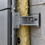
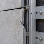
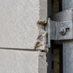
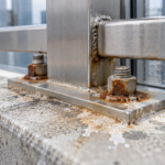
- Most commercial skylight failures originate at the curb interface, not the glazing unit that receives all the warranty attention.
- Standard 2D thermal modeling misses corner geometry, leaving effective perimeter U-factors 30 to 50 percent higher than compliance documents show.
- Condensation accumulating at the curb base can deposit gallons of water per heating season into wood nailer substrates without any bulk water intrusion event.
- Substrate degradation silently compromises anchor pull-out capacity and air barrier continuity long before interior damage becomes visible.
- A thermally broken cap flashing, designed condensate drainage and a joint pre-installation inspection checklist can prevent failures costing hundreds of thousands of dollars.
A forensic investigation on a four-year-old corporate headquarters reveals that the thermally broken aluminum skylight units are performing exactly as specified. The IGUs are intact, the condensation weep paths are clear and the glazing manufacturer’s warranty is untouched.
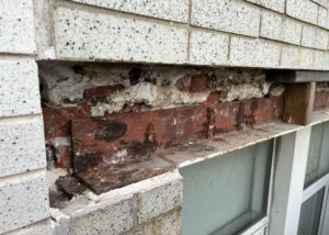
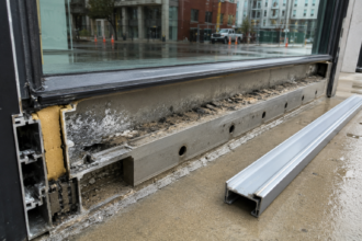
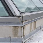
The failure is in the 3-inch gap between the skylight curb base and the TPO membrane termination bar, where standing water has been wicking into the wood nailer substrate for 47 months without a single commissioned inspection. By the time the interior ceiling tiles signal the problem, the structural curb has lost 60 percent of its load-bearing capacity and the air barrier has been breached at every perimeter anchor point.
The glazing unit did its job. Everything around it failed.
The Glazing Unit Is Not the Problem: The Curb Interface Is
The building envelope industry has a persistent attribution problem with skylight failures. Warranty claims route to glazing manufacturers.
Callbacks trigger glazing contractor site visits. The forensic investigation, if one gets commissioned at all, starts with the IGU.
This reflex misses the actual failure locus in the majority of chronic moisture cases I have investigated.
The glazing assembly and the curb system are distinct components, frequently specified by different parties with no envelope-level coordination between them. The glazing assembly covers the IGU, the aluminum frame and the thermal break.
AAMA 2510, the governing voluntary specification for skylights, addresses those components directly. What AAMA 2510 explicitly excludes is the curb substrate, the cap flashing geometry and the membrane termination interface.
That exclusion is not a flaw in the standard; it reflects the actual scope of the glazing manufacturer’s responsibility. The flaw is in how project teams interpret that boundary.
Glazing specifications reference AAMA 2510 and NFRC 100 thermal performance data. Roofing specifications reference NRCA details and manufacturer membrane requirements.
Nobody owns the 3-inch transition zone between them. That gap is where the water goes.
The central argument here is direct: chronic condensation accumulation and structural curb degradation originate at the perimeter flashing geometry, not at the glazing unit that gets all the attention.
What makes this attribution problem durable is that it is structurally reinforced by how projects are contracted. The glazing subcontractor’s scope terminates at the frame seat.
The roofing subcontractor’s scope terminates at the termination bar. The general contractor has no technical basis to adjudicate the gap between them and the architect’s detail, if one exists at all, typically shows a schematic cross-section that does not resolve the actual field condition at the curb corner.
On design-build projects the coordination gap is sometimes worse, because the performance specification that drives the design-build envelope scope will reference AAMA 2510 compliance and NFRC-rated U-factors without specifying any performance requirement for the curb interface itself. The result is a fully documented, fully warranted assembly with an unspecified and unverified transition zone that carries the actual moisture risk.
Thermal Bridge Geometry at the Curb Perimeter: What the Model Doesn’t Show
The thermal bridge problem at a skylight curb is three-dimensional in a way that standard energy compliance modeling does not capture. At the curb corner, three distinct assemblies intersect: the vertical curb wall, the sloped glazing frame and the horizontal roof membrane plane.
The heat flow path through that intersection cannot be accurately characterized by a 2D linear thermal transmittance (psi-value) calculation. ISO 10211, the international standard for thermal bridge analysis, requires 3D simulation for corner conditions precisely because 2D methods systematically underestimate heat flux at geometric intersections.
Commercial skylight details almost never invoke ISO 10211. They rely on 2D THERM models of the frame cross-section, which capture the thermal break performance accurately and miss the corner geometry entirely.
The aluminum cap flashing compounds this. Even when the skylight frame carries a legitimate thermal break, the cap flashing typically bridges continuously from the interior curb face to the exterior membrane termination.
That aluminum path bypasses the thermal break entirely. It is a conductive short-circuit running the full perimeter of the assembly and it does not appear in the frame U-factor that gets submitted for compliance.
Point thermal bridges at anchor fasteners make this worse. Each fastener penetrating the curb substrate creates a localized cold spot that can drop below the dew point of occupied commercial space independently of the field glazing performance.
In IECC Climate Zones 5 through 7, those fastener locations will condense during heating season whether or not the IGU center-of-glass temperature is within specification.
ASHRAE 90.1-2022 Section 5. 5.
3. 2 provides the skylight U-factor compliance pathway used on most commercial projects.
That pathway does not require 3D simulation of curb geometry. An assembly can be fully compliant on paper while the installed perimeter thermal bridge drives surface temperatures well below the dew point of a space maintained at standard HVAC setpoints.
Compliant is not the same as performing.
The practical consequence of relying exclusively on 2D THERM outputs is that the compliance documentation submitted to the authority having jurisdiction will show a thermally broken frame with a U-factor that satisfies the prescriptive table in 90.1 Appendix A, while the installed assembly has an effective perimeter U-factor that is substantially higher once the cap flashing conduction path and fastener point bridges are accounted for. A 3D simulation of a representative curb corner using HEAT3 or equivalent software will routinely show effective corner U-factors 30 to 50 percent higher than the 2D frame section predicts.
That delta is not a modeling artifact. It is the heat that drives the condensation that initiates the substrate degradation.
Projects in Climate Zone 6 with interior humidity setpoints above 30 percent relative humidity are particularly exposed to this gap between modeled and actual thermal performance at the curb perimeter.
Condensation Accumulation Mechanics: Where the Water Actually Goes
Interior warm humid air contacts the cold curb perimeter surface first. Not the glazing center-of-glass.
The cap flashing underside and the curb interior face are the coldest accessible surfaces in the assembly during heating season and that is where condensation initiates. Water forms, runs down the curb interior face and accumulates at the base where the curb meets the roof membrane termination bar.
It has nowhere designed to go.
Skylight manufacturers engineer internal condensation gutters to manage condensation forming on the glazing frame itself. Those gutters work as designed.
They do not intercept condensation forming on the curb interior face below the frame seat. That water is outside the designed drainage path.
It sits at the curb base, in contact with the wood nailer substrate and the membrane termination and it begins wicking laterally and downward through capillary action.
This failure mode evades standard water infiltration testing. ASTM E1105 tests for water penetration under static or cyclic pressure differentials applied to the exterior face of the assembly.
It does not replicate the condensation accumulation mechanism, which is an interior-sourced moisture load deposited at the curb base over months of heating season operation. A skylight assembly can pass ASTM E1105 without qualification and still be accumulating condensate at the curb base every winter.
ASHRAE 160-2021 provides the hygrothermal analysis framework applicable to this condition. Dew point mapping of the curb perimeter cross-section, using actual interior humidity setpoints and exterior design temperatures for the project climate zone, will identify the condensation risk surfaces before construction.
This analysis is rarely included in commercial skylight specifications. It should be a standard deliverable for any sloped glazing installation in Climate Zones 4 through 7.
The condensation accumulation rate at the curb base is not trivial. In a Climate Zone 5 office building maintained at 70 degrees Fahrenheit and 35 percent relative humidity during heating season, the dew point of interior air is approximately 42 degrees Fahrenheit.
A continuous aluminum cap flashing without a thermal break will routinely reach surface temperatures below that threshold on the interior curb face during design heating conditions. A 10-foot skylight perimeter section operating under those conditions can deposit several ounces of liquid water per day at the curb base during sustained cold weather.
Over a heating season of 150 days, that accumulation is measured in gallons, not drops. The wood nailer substrate does not need a bulk water intrusion event to reach damaging moisture content levels.
It needs only the slow, consistent, unmanaged condensate load that the assembly is generating by design every winter.
The Structural Curb Substrate: What Degrades and How Fast
Wood nailer curb construction remains the dominant practice in commercial low-slope roofing despite being the most moisture-vulnerable substrate available. Roofing contractors use it because it is cost-effective, dimensionally familiar and compatible with standard termination bar and cap flashing details.
The structural consequence of that choice only becomes visible after the damage is done.
The American Wood Council establishes 19 percent moisture content as the threshold above which fungal decay initiates in structural lumber in service. At the condensation accumulation rates typical of an unaddressed curb interface in a Climate Zone 5 or 6 building, the wood nailer substrate can reach and sustain moisture content above that threshold within 18 to 24 months of first occupancy.
Structural capacity loss follows. It does not announce itself on the exterior.
Cold-formed steel curb alternatives eliminate the biological decay mechanism. They introduce their own failure path.
Corrosion at fastener penetrations in steel curbs is a documented problem, particularly where dissimilar metals contact each other at the cap flashing connection. Steel curbs do not resolve the thermal bridge geometry; in some configurations they accelerate it by providing a more conductive path through the assembly perimeter than wood.
The structural consequence that matters most is anchor pull-out capacity. Skylight glazing systems transfer wind uplift loads through the frame into the curb substrate.
FM Global Property Loss Prevention Data Sheet 1-49 addresses curb substrate anchorage requirements for roofing assemblies and establishes pull-out resistance minimums that assume an intact substrate. When the substrate degrades, that load path is compromised.
The fasteners are still there. The wood around them is not carrying the load it was designed to carry.
There is no exterior visual indicator until the frame moves.
The degradation timeline is worth stating precisely because it defines the window during which intervention is still cost-effective. Moisture content monitoring of wood nailer substrates in instrumented research assemblies shows that once the substrate exceeds 25 percent moisture content, fungal colonization is typically established within 60 to 90 days under temperate conditions.
Beyond that threshold, structural capacity loss is progressive and does not reverse when the moisture source is removed. The wood does not recover its original density.
A substrate that has cycled above 25 percent moisture content for two or more heating seasons will have measurably reduced fastener pull-out resistance even if it appears visually intact from the exterior. Probe testing with a moisture meter at the curb base, conducted during a commissioning inspection or periodic maintenance visit, is the only reliable way to catch this condition before it reaches the point where the frame is at structural risk.
That test takes approximately 10 minutes per skylight unit. It is almost never performed.
Air Barrier Continuity Failure at the Curb Transition: The Invisible Consequence
The air barrier is the control layer most damaged by curb substrate degradation and the least likely to be identified as a consequence of skylight failure. When the structural curb degrades and anchor points shift, the air barrier membrane that was sealed to the curb perimeter at each fastener location opens.
Each breach is small. The aggregate effect across a full skylight perimeter is not.
Air leakage transports moisture at orders of magnitude greater than vapor diffusion through the same assembly area. A compromised air barrier at the curb perimeter in a heating-dominated climate drives warm interior air directly into the cold curb substrate, where it deposits moisture through condensation at a rate that accelerates the degradation already initiated by the condensation accumulation at the base.
The two failure mechanisms are self-reinforcing.
ASTM E2357 tests air barrier assemblies for air leakage resistance under cyclic loading. That test is conducted on representative wall assemblies under laboratory conditions.
It does not address the field condition where substrate degradation has compromised the anchor points that hold the air barrier membrane in plane. The air barrier that passed E2357 as a system is no longer the system installed in the field after 36 months of unaddressed moisture accumulation at the curb base.
Continuity between the roof air barrier and the skylight curb air barrier is a coordination item that falls between the roofing specification and the glazing specification. Neither subcontractor owns it.
Without an explicit air barrier continuity plan documented in the envelope drawings and verified during commissioning, this transition defaults to field improvisation. Field improvisation at air barrier transitions fails.
It fails consistently and it fails in ways that are expensive to remediate.
The detection problem compounds the remediation cost. Whole-building air leakage testing per ASTM E779 or ASTM E3158 will identify that a building has elevated air leakage, but it will not localize the source to the skylight curb perimeter without supplementary diagnostic work.
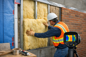
Infrared thermography conducted under pressurization, per ASTM C1060, can locate air leakage pathways at the curb transition if the thermal contrast between interior and exterior is sufficient, typically requiring at least a 10-degree Fahrenheit delta-T across the assembly. In practice, the curb perimeter air leakage is often attributed to other envelope transitions during diagnostic surveys because the skylight curb is not on the standard checklist of suspected locations.
The result is that remediation work gets directed at curtainwall sill conditions or penetration seals while the curb perimeter continues to leak. Targeted pressurization of the skylight curb zone using a blower door with localized depressurization, combined with smoke pencil tracing at the interior curb face, is a more reliable diagnostic approach for isolating this specific failure location.
That level of diagnostic specificity requires an envelope commissioning agent who has identified the curb transition as a risk location before the investigation begins.
What a Defensible Curb Interface Detail Actually Requires
The detail that addresses these failure modes is not complicated. It is simply not standard.
It requires deliberate specification and envelope-level coordination that most commercial projects do not currently provide.
The cap flashing must be thermally broken from the interior curb face. Continuous aluminum cap flashing bridging from interior to exterior is not acceptable in Climate Zones 4 through 7 regardless of the frame’s thermal break performance.
A poured-and-debridged or polyamide-broken cap flashing profile or a two-piece cap with a thermal isolator at the curb top, eliminates the perimeter conductive short-circuit that 2D frame modeling misses.
The curb base must have a designed condensation drainage path that is independent of the glazing frame’s internal gutter system. A sloped sill at the curb interior base, directing any accumulated condensate to a weep at the membrane termination, addresses the accumulation mechanism that ASTM E1105 cannot detect and ASHRAE 160-2021 analysis will predict.
The air barrier transition from roof membrane to curb perimeter must be documented as a specific line item in the envelope drawings, assigned to a single responsible party and verified by the envelope commissioning agent before the skylight frame is set. NIBS Guideline 3-2012 provides the commissioning framework.
The curb interface transition should be an explicit inspection point, not an assumed condition.
The specification language that makes these requirements enforceable is worth stating directly. The project manual should include a Division 08 skylight section that explicitly states the curb substrate, cap flashing thermal performance and condensate drainage path are within the skylight installer’s scope of coordination, even if they are not within the glazing manufacturer’s product warranty.
That scope assignment does not have to mean the skylight contractor builds the curb. It means the skylight contractor is responsible for verifying that the curb as built meets the thermal and drainage requirements documented in the envelope drawings before the frame is set.
A pre-installation inspection checklist, signed by the skylight installer and the roofing contractor jointly, with the envelope commissioning agent present, is the procedural mechanism that closes the coordination gap. That checklist should include a moisture content reading of the wood nailer substrate at the time of frame installation, establishing a baseline for future comparison.
The cost of that inspection is measured in hours. The cost of the remediation it prevents is measured in hundreds of thousands of dollars on a mid-size commercial project.
The Commission Nobody Orders Until It’s Too Late
The skylight curb interface is not a detail that fails dramatically. It fails slowly, invisibly and expensively.
The glazing unit performs. The warranty stays intact.
The interior shows nothing until the substrate has been compromised for years.
Envelope commissioning protocols for curtainwall and storefront systems now routinely include air barrier continuity verification, thermal imaging under heating season conditions and water infiltration testing at transition zones. Sloped glazing receives none of that scrutiny on most commercial projects because the glazing manufacturer’s documentation looks complete and the roofing contractor’s termination bar looks sealed.
The gap between those two observations is where the building is failing.
The practical recommendation is this: if you are reviewing construction documents for a project with integrated skylights or sloped glazing in Climate Zones 4 through 7, add a mandatory line item requiring hygrothermal analysis per ASHRAE 160-2021 of the curb perimeter cross-section, a thermally broken cap flashing detail with a designed condensate drainage path and a specific air barrier continuity plan at the curb-to-roof transition. Then require commissioning verification of