Cold-Bent Glazing in Curtainwall: Residual Stress and Seal Failure
Within 18 months of substantial completion on a mid-rise mixed-use project in the Southeast, the building owner was looking at condensation between lites on multiple cold-bent IGU panels across two facade elevations. The investigation that followed was instructive in the worst possible way.
The cold-bending process had distorted the edge seal geometry beyond the IGU manufacturer’s published tolerance band. The framing system’s gasket compression had never been validated against the actual bent radius.
The project team had copied a flat-glass curtainwall specification verbatim and applied it to a system that shared almost nothing with flat glass in terms of stress state, seal behavior or framing compatibility. Nobody had flagged the gap at design, submittal review or installation.
The owner was facing full IGU replacement on a system less than two years old.
This is not an isolated case. It is the predictable outcome of specifying cold-bent glazing without understanding what it actually does to the glass, the seal and the framing assembly.
What Cold-Bent Glazing Actually Is and What It Is Not
Cold-bending is elastic deformation of flat glass within the framing system at ambient temperature, without thermal reformation. The glass is fabricated flat, shipped flat and then physically forced into a curved geometry during installation by the framing system itself.
It stays curved because the frame holds it there. The glass never stops resisting that curvature.
This is fundamentally different from hot-bent glass, where the lite is heated above its softening point, formed to a curved mold and allowed to cool in that shape. Hot-bent glass, whether tempered per ASTM C1048 or heat-soaked, carries a stress profile consistent with its final geometry.
Cold-bent glass carries a stress profile permanently in conflict with its geometry.
Cold-bent IGUs are not a monolithic product category. Radius capability varies by glass thickness, lite size, aspect ratio and IGU configuration.
A 6mm monolithic lite behaves differently than a 1-inch IGU with two lites of laminated glass. The market driver pushing cold-bending into more projects is straightforward: architects want curved facades, hot-bent glass costs more and carries longer lead times and cold-bending appears to solve both problems.
It does, temporarily. The performance tradeoffs accumulate over time.
There is no ASTM standard that governs cold-bent IGU performance thresholds the way ASTM C1048 governs heat-treated flat glass. That regulatory gap is not an accident; it reflects how poorly understood the product category remains.
The lead time argument deserves more scrutiny than it typically receives in project planning. Hot-bent glass from a domestic fabricator can run 14 to 20 weeks for tempered curved units depending on mold availability and production scheduling.
Cold-bent glass ships on the same schedule as flat glass because it is flat glass. On a compressed design-build schedule, that difference can feel decisive.
What project teams rarely model is the cost of the failure scenario: full IGU replacement at 18 to 24 months, including scaffolding, framing disassembly, new unit fabrication and the owner relations damage that accompanies visible condensation on a building that has barely been occupied. The schedule savings from cold-bending evaporate quickly against that accounting.
Laminated cold-bent IGUs introduce an additional variable that monolithic cold-bent lites do not. The interlayer in a laminated lite, whether PVB or ionoplast, has its own viscoelastic response to sustained stress.
Under long-term cold-bending loads, PVB interlayers can exhibit creep behavior that shifts load distribution between the two glass plies in ways that are not captured in standard laminated glass design methods. Ionoplast interlayers are stiffer and transfer more load between plies, which can actually increase edge stress concentration in a cold-bent laminated unit relative to a PVB equivalent at the same radius.
Neither behavior is addressed in ASTM C1172, which governs laminated architectural flat glass and makes no provision for sustained cold-bending loads.
How Cold-Bending Loads the Glass
The glass in a cold-bent assembly is under continuous elastic stress. It wants to return to flat.
That force does not dissipate; it transfers continuously into the framing system and the edge seal for the life of the installation. Understanding the magnitude of that load requires understanding the relationship between bend radius, glass thickness and induced surface stress.
Stress in a cold-bent lite scales inversely with bend radius and directly with glass thickness. Tighter radii on thicker glass produce the highest stress concentrations.
But the relationship is not linear at the corners and edges of the lite, where bending stress concentrates due to the biaxial nature of the deformation. A lite bent to a tight radius in one direction develops stress concentrations at its corners that can approach the modulus of rupture of annealed glass under combined thermal and mechanical loading.
Thermal cycling amplifies this. As the facade assembly heats and cools through daily and seasonal cycles, the glass expands and contracts.
In a flat assembly, that movement is accommodated by gasket compression and sealant shear. In a cold-bent assembly, thermal movement adds to the already-loaded stress state at the point of maximum curvature.
ASTM E1300 load resistance tables assume flat geometry. There is no provision in E1300 for the sustained stress state of a cold-bent lite, which means structural glass calculations performed on cold-bent units using E1300 are, at best, incomplete.
To put numbers to this: a 10mm annealed lite cold-bent to a 2,500mm radius develops a surface stress on the order of 8 to 10 MPa from bending alone, before any wind, thermal or self-weight load is applied. The modulus of rupture for annealed glass is typically cited at 41 MPa under short-duration loading, but that figure degrades under sustained stress through a mechanism called static fatigue, where surface flaws propagate slowly under constant tensile stress even at loads well below the instantaneous failure threshold.
A cold-bent annealed lite sitting at 20 to 25 percent of its nominal modulus of rupture, continuously, for years, is not in a stable condition. Heat-strengthened glass per ASTM C1048 carries a surface compression of 3,500 to 7,500 psi that offsets tensile bending stress, which is one reason heat-strengthened glass is strongly preferred over annealed glass in cold-bent applications.
Fully tempered glass at 10,000 psi minimum surface compression provides more margin still, but introduces the nickel sulfide spontaneous breakage risk that is statistically elevated under sustained stress.
Glass breakage is not the primary failure mode specifiers should worry about. Seal distortion and gasket rollout are.
That said, spontaneous breakage from nickel sulfide inclusions is statistically elevated in cold-bent units under sustained stress and that risk deserves acknowledgment in the project risk register even if it is not the most probable failure path. Heat soaking per EN 14179-1 reduces but does not eliminate that risk and heat-soaked tempered glass is not a standard domestic stock item.
Specifying it adds cost and lead time that partially offsets the schedule advantage cold-bending was supposed to provide in the first place.
Edge Seal Distortion and IGU Durability
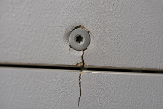
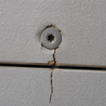
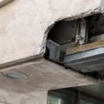
The IGU spacer bar is manufactured flat. Cold-bending deforms it into a curved geometry it was never designed to hold, creating non-uniform compression across the primary and secondary seal perimeter.
That non-uniformity is the mechanism behind the failure mode most specifiers miss entirely.
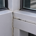
Non-uniform seal compression creates preferential pathways for moisture vapor infiltration. The primary seal in a dual-seal IGU system, typically polyisobutylene, is a pressure-sensitive adhesive that depends on uniform contact stress to function.
Deform the spacer bar and you reduce contact stress at the points of maximum curvature. Reduce contact stress and you create a vapor pathway.
The desiccant in the spacer bar can only absorb so much moisture before it saturates. Once it saturates, fogging between the lites is inevitable.
The secondary seal, whether silicone or polysulfide, is designed to resist shear loads from differential thermal movement between the two lites. Cold-bending introduces peel stress at the glass-to-spacer interface.
That is a different load mode entirely and the secondary seal is not designed for it.
ASTM E2190 governs insulating glass unit performance and evaluation. Its test protocol uses flat specimens only.
Cold-bent units are not evaluated under E2190. This means IGU warranties are routinely voided by cold-bending and most specifiers have no idea that is the case because nobody reads the warranty exclusions until there is a claim. IGMA guidance on acceptable cold-bending limits exists, but most IGU manufacturers publish minimum radius requirements that are more conservative than what architects typically specify.
The submittal review process almost never catches this discrepancy.
The spacer bar material compounds this problem in ways that vary by product selection. Aluminum spacer bars are stiffer than warm-edge alternatives such as thermoplastic spacer or stainless steel flexible spacer systems.
A rigid aluminum spacer bar resists deformation into a curved geometry, which means the bending load concentrates at the corners of the unit where the spacer bar is crimped. Warm-edge spacer systems with more flexible construction conform more readily to the bent geometry, which distributes the deformation more evenly along the seal perimeter.
That does not eliminate the problem, but it changes where the failure initiates. Projects that have used flexible warm-edge spacer systems in cold-bent applications consistently show longer time-to-failure than equivalent projects with aluminum spacer bars, though failure still occurs when the bend radius falls below the manufacturer’s minimum.
The specification should identify spacer bar type as a cold-bending variable, not leave it as a contractor option.
Dual-seal IGU construction with silicone secondary seal performs better in cold-bent applications than polysulfide secondary seal for one specific reason: silicone retains flexibility at low temperatures and under sustained deformation better than polysulfide. Polysulfide secondary seal becomes progressively less flexible over time through continued cure, which reduces its ability to accommodate the ongoing peel stress that cold-bending introduces at the glass-to-spacer interface.
In cold climates where facade temperatures drop below 0°F regularly, polysulfide secondary seal in a cold-bent IGU is a combination that accelerates seal failure measurably.
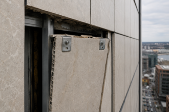
Gasket Compression Limits and Framing Compatibility
Standard curtainwall pressure plate and gasket systems are designed and tested for flat glass. Gasket compression targets, typically 15 to 25 percent compression set, assume uniform contact across the full lite perimeter.
Cold-bent glass violates that assumption at the point of maximum curvature, where the glass lifts away from the gasket and reduces compression below the threshold required for air and water resistance.
This failure is invisible at installation. The gasket looks compressed.
The pressure plate is torqued to specification. Everything appears correct because the inspection protocol was written for flat glass.
The problem only becomes apparent during weather testing or, more often, during the first heating season when thermal movement opens the gap further.
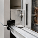
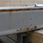
Framing systems with thermally broken pressure plates have additional compliance in the assembly that can mask inadequate gasket contact. The thermal break introduces a degree of flexibility that allows the pressure plate to appear properly seated while the gasket behind it is bridging across the curvature rather than conforming to it.
Storefront systems are at higher risk than unitized curtainwall for a specific reason: storefront framing has less structural depth and lower tolerance for the out-of-plane loads that cold-bending introduces continuously into the framing members. AAMA 501.1 field water penetration testing does not account for cold-bent glass geometry.
A mock-up that passes AAMA 501.1 with flat glass tells you nothing about how the same framing system will perform with cold-bent units. The AAMA 800-series gasket compression set limits are defined for flat applications.
Full stop.
The gasket durometer selection compounds the problem when it is carried over from a flat-glass specification without adjustment. EPDM gaskets at 50 to 60 Shore A durometer, which are standard for flat curtainwall applications, do not conform readily to the gap geometry that cold-bending creates between the glass edge and the framing pocket.
A lower durometer gasket, in the 40 to 45 Shore A range, conforms better to irregular contact surfaces but sacrifices compression set resistance over time. There is no published AAMA guidance that resolves this tradeoff for cold-bent applications because the AAMA gasket standards were not written with cold-bent geometry in mind.
The framing manufacturer needs to make this determination through physical testing at the specified radius, not through interpolation from flat-glass data. When that testing has not been done, the specifier is accepting an unknown gasket performance condition on a system that is already operating outside its validated range.
Unitized curtainwall systems introduce a different framing compatibility concern. The stack joint between unitized panels relies on pressure-equalized rain screen performance, where the outer gasket line manages air pressure and the inner gasket line provides the primary water barrier.
Cold-bending a unitized panel distorts the stack joint geometry at the panel corners, where the horizontal and vertical framing members meet. That corner condition is the most geometrically complex point in the assembly and the point where cold-bending deformation is highest.
Stack joint performance at cold-bent panel corners has not been systematically studied and field evidence from failed projects consistently shows water infiltration initiating at those corner conditions before it appears at the field of the panel.
What Current Performance Specifications Don’t Cover
Standard curtainwall specifications under CSI MasterFormat Section 08 44 13 reference AAMA, ASTM and NFRC performance criteria that were developed and validated exclusively on flat glass assemblies. Specifiers copy forward air infiltration requirements per ASTM E283, water resistance requirements per ASTM E331 and structural performance requirements per ASTM E330 without adding a single cold-bent-specific provision.
The specification reads as though the glass is flat because the template it was built from assumed flat glass.
There is no current AAMA or ASTM standard that establishes performance thresholds specifically for cold-bent IGUs in curtainwall assemblies. That gap is not a technicality.
It means every cold-bent curtainwall project is operating outside the validated performance envelope of the standards it claims to meet. The specifier bears responsibility for that gap if they do not explicitly address it.
What the specification needs, at minimum, is a cold-bending radius limit tied to the IGU manufacturer’s published tolerance, a requirement that gasket compression be validated by the framing manufacturer at the specified radius before submittal approval and a clear statement that ASTM E2190 warranty coverage does not apply to cold-bent units and that the contractor must obtain written confirmation from the IGU manufacturer of acceptable bend radius before fabrication.
None of that is standard language. None of it appears in any master specification template I have reviewed.
It has to be added by the specifier who understands what cold-bending actually does to the assembly.
The NFRC thermal performance rating system creates a parallel specification gap that receives even less attention. NFRC 100 center-of-glass U-factor calculations and NFRC 200 solar heat gain coefficient ratings are based on flat glass geometry.
Cold-bending changes the effective angle of incidence across the lite surface, alters the convective air movement in the cavity between lites and modifies the edge conduction path through the deformed spacer bar. None of those effects are captured in a standard NFRC label.
A cold-bent IGU specified to meet a particular U-factor under NFRC 100 may not achieve that U-factor in its installed, bent condition. Energy code compliance documentation that relies on NFRC-rated values for cold-bent units is technically incomplete and that incompleteness is invisible in the permit review process because no jurisdiction has a cold-bent-specific energy code provision to check against.
The specification should also address the structural silicone sealant condition at the glass edge in structurally glazed cold-bent applications. ASTM C1184 governs structural silicone sealant and its bite dimension calculations assume flat glass with predictable load paths.
Cold-bending introduces a continuous peel component at the silicone-to-glass bond line that is not accounted for in standard bite dimension calculations. Facade engineers who perform structural silicone design on cold-bent applications using C1184 methodology without a cold-bending load modifier are underdesigning the sealant connection.
The silicone manufacturer’s technical representative should be engaged to provide cold-bending-specific bite dimension guidance before the specification is finalized and that engagement should be documented in the project record.
The Submittal Review Gap
Submittal review is where cold-bent glazing projects most commonly fail to catch the problems that later become failures. The glazing contractor submits an IGU product data sheet that was written for flat glass.
The facade engineer reviews it against a specification written for flat glass. The IGU manufacturer’s radius minimums are buried in a technical bulletin that nobody requested.
The framing manufacturer’s gasket compression data is based on flat mock-up testing. Every document in the submittal package is internally consistent and entirely inadequate for the actual condition.
The facade engineer reviewing this submittal needs to ask three questions that the standard review checklist does not include. First: what is the minimum bend radius published by the IGU manufacturer for this specific unit configuration and does the specified radius meet or exceed it?
Second: has the framing manufacturer validated gasket compression performance at the specified radius through physical testing, not calculation? Third: does the cold-bending of this unit void the IGU warranty and if so, what alternative warranty coverage is the contractor providing?
If the answers to those questions are not in the submittal, the submittal is incomplete. Return it.
The submittal review gap extends beyond the IGU and framing documentation. The structural silicone sealant submittal, if the project uses structural glazing, should include a letter from the sealant manufacturer confirming that the specified bite dimension is adequate for the cold-bending load condition at the specified radius.
Most structural silicone submittals consist of a product data sheet, a cure certificate and a standard bite dimension calculation. None of those documents address cold-bending.
The reviewer who accepts that package without requesting cold-bending-specific confirmation has approved a structural connection that may be undersized for its actual load condition.
The glazing contractor’s installation procedure submittal is equally important and equally likely to be inadequate. Cold-bending a large IGU into a framing bay requires a defined installation sequence: which corners are set first, how the unit is progressively bent into the frame, what temporary support is used during installation and how the pressure plate is torqued in sequence to distribute the bending load evenly across the gasket.
An installation procedure that simply says “install per manufacturer’s recommendations” is not a cold-bending installation procedure. It is a flat-glass installation procedure applied to a condition it was never written for.
The facade engineer should require a cold-bending-specific installation narrative from the glazing contractor before the first unit is installed and that narrative should be reviewed against the framing manufacturer’s recommendations for the specific radius being installed.
Shop drawing review for cold-bent applications should include a check of the framing pocket depth at the point of maximum curvature. As the glass bends into the frame, the edge of the lite at the point of maximum curvature moves relative to the framing pocket in a way that can reduce the glass bite below the minimum required by AAMA 501.6 or the project specification.
Standard shop drawing review checks glass bite at the corners and midpoints of flat lites. Cold-bent shop drawings need a glass bite check at the point of maximum curvature specifically, because that is where the geometry is most different from flat and where bite reduction is most likely to occur.
What the Field Requires Before Glazing Begins
Before a single cold-bent IGU is installed on a project, the project team needs a cold-bending protocol that does not exist in any standard specification section. This is not a best-practice recommendation.
It is a minimum threshold for responsible practice on a system that operates outside the tested performance range of every standard it will be evaluated against.
The protocol needs to include a radius verification requirement: every framing bay receiving a cold-bent unit must be surveyed to confirm the as-built radius matches the design radius within a defined tolerance. Framing fabrication tolerances accumulate.
A design radius of 3,000mm can easily become 2,700mm in the field and that difference matters for seal performance.
The project also needs a cold-bent-specific water penetration test on a mock-up that replicates the actual bent geometry. AAMA 501.1 on a flat mock-up is not a substitute.
The test specimen must be bent to the specified radius before testing begins. If the framing and glazing contractor cannot produce that mock-up, the project team does not yet know whether the system performs.
They are speculating.
The radius verification survey should use a defined measurement methodology, not a visual check. A digital level and chord-length measurement across the framing bay gives a calculable radius that can be compared against the design intent.
Some project teams have used photogrammetry for this verification on complex curved facades, which provides a full-field radius map rather than point measurements. Either method is acceptable provided the tolerance band is defined in the protocol before measurement begins.
A tolerance of plus or minus 5 percent of the design radius is a reasonable starting point for most applications, but the IGU manufacturer should confirm that the tolerance band is consistent with their published minimum radius before it is written into the protocol.
The cold-bent mock-up test should be conducted at the design radius and at the tolerance limit radius simultaneously if budget allows. Testing only at the design radius tells you the system performs under ideal conditions.
Testing at the tolerance limit radius tells you whether the system survives the worst-case field condition. The difference in test cost is small relative to the information value.
A project that has tested at both conditions has a defensible performance baseline. A project that has tested only at the design radius has a performance baseline that does not account for the field conditions it will actually encounter.
Pre-installation inspection of each IGU before it enters the framing bay should include a check of the spacer bar for any pre-existing deformation from shipping or handling. Cold-bent IGUs are shipped flat, but large units can develop slight permanent deformation in the spacer bar from improper stacking or support during transit.
A spacer bar that arrives with even minor deformation will perform worse under cold-bending than an undamaged unit. That inspection step takes less than two minutes per unit and eliminates a variable that has contributed to early failures on projects where it was not performed.
Specifiers who have watched cold-bent IGU failures develop over 18 to 36 months know that the condensation between lites is not the beginning of the problem. It is the visible confirmation of a failure that started at installation.
Get the protocol right before the glass goes in.