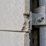


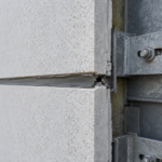

- A Denver GFRC spandrel panel delaminated from thermal bow cycling after anchor embedment fell below specification minimums that no one verified.
- PCI MNL-128-01 has not been updated since 2001 and leaves critical gaps in bonding pad dimensions and embedment depth requirements.
- Reducing anchor embedment from 1.5 to 1.0 inches can cut allowable pullout load by 40 to 60 percent depending on mix design.
- A 2019 audit of 22 GFRC facade projects found 14 had anchor embedment depths that failed to meet their own project specifications.
- Defensible specifications must define bonding pad minimums, embedment tolerances, third-party core sampling and thermal bow fatigue analysis requirements.
GFRC Panel Anchor Limits: What Specs Miss
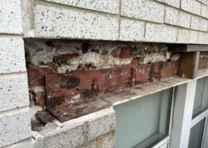
A GFRC spandrel panel on a 12-story mixed-use project in Denver delaminated at its flex anchor connection 18 months after installation. Not from seismic loading.
From cumulative thermal bow cycling that had progressively worked the anchor stud out of an undersized panel skin. The skin at the anchor zone measured 0.4 inches, well below the 0.
75-inch minimum the project specification nominally required. Shop drawings had never flagged the discrepancy.
The design team had never verified it. The incident triggered a full facade audit, replacement of 34 panels and a legal dispute that remains unresolved.
That project is not an outlier. It is a preview.
Why GFRC Is Back: And Why That Creates Risk
Renewed demand for sculptural, textured and curved facade surfaces is pushing GFRC into mid-rise commercial projects where it was rarely specified a decade ago. Architects want the formal freedom that precast concrete cannot deliver at comparable weight.
Terracotta offers texture but not geometry. GFRC fills that gap and specification volume is climbing as a result.
The problem is that design teams migrating from precast or terracotta carry over detailing assumptions that do not transfer to GFRC’s thinner, more flexible panel geometry. Precast panels are typically 4 to 6 inches thick with substantial bearing area at anchor locations.
GFRC skins run 0.5 to 0. 75 inches.
Those are not comparable structural conditions and treating them as such produces failures. A precast bearing pad can accommodate a 1.5-inch anchor stud with substantial concrete cover on all sides.
A GFRC bonding pad at a 0.625-inch skin location has almost no geometric margin before the stud is effectively at the face. That distinction should be driving specification language.
It rarely does.
GFRC’s lower self-weight is cited constantly as a benefit. It is a real benefit.
But reduced mass also means reduced anchor bearing capacity, reduced resistance to out-of-plane thermal bow and reduced tolerance for embedment depth errors. Nobody puts that in the spec narrative.
A 10-pound-per-square-foot GFRC panel and a 75-pound-per-square-foot precast panel do not share the same structural logic at the connection and the specification should reflect that difference explicitly rather than importing precast anchor language into a GFRC section without modification.
The primary North American reference, PCI MNL-128-01 “Recommended Practice for Glass Fiber Reinforced Concrete Panels,” has not been substantively updated since 2001. The facade industry has changed substantially in the intervening two decades. Panel geometry has grown more complex, production methods have diversified and project schedules have compressed in ways that reduce production oversight time.
The gap between architectural enthusiasm and structural engineering familiarity with GFRC is widening precisely as specification volume increases. That combination produces exactly the kind of failure described above.
Design teams writing GFRC specifications today are working from a reference document that predates the current generation of complex-geometry panel applications by more than 20 years.
Anatomy of a GFRC Panel: What the Specification Often Gets Wrong
A GFRC panel is not a monolithic element. It is a composite assembly with at least three structurally distinct zones and each zone has a different failure mode that demands separate specification attention.
The face skin is the outermost layer, typically 0.5 to 0. 75 inches of premix or spray-up GFRC.
It carries out-of-plane wind and thermal loads and transfers them to the backup frame. Behind it sit integral ribs or a steel stud frame bonded to the skin, which provide in-plane stiffness and carry gravity loads to the anchor points.
The bonding pad is the thickened GFRC zone cast directly around the anchor stud. It is the load transfer element.
It is also the element whose dimensions are most rarely called out explicitly in project specifications.
Skin thickness is not uniform across a panel. Corners, returns and areas around penetrations are chronically thin in spray-up production, frequently 20 to 35 percent below nominal specification thickness.
These are also the locations where anchor points often fall on complex geometry panels. The combination of reduced skin thickness and anchor proximity is where failures initiate.
A panel with three anchor points clustered near a 90-degree return is a high-risk configuration that a flat-panel production standard does not address. The specification needs to address it directly, with thickness minimums stated at defined high-risk zones rather than as a single global value.
Mix design variables compound the problem. AR glass content, polymer-to-cement ratio and water-cement ratio all directly affect long-term tensile and flexural strength, yet these are routinely left to the manufacturer’s discretion without third-party verification.
ASTM C1228 “Standard Practice for Preparing Coupons for Tensile and Flexural Testing of Glass-Fiber Reinforced Concrete” provides the verification framework. Coupon testing should be required at production start and at defined intervals during the production run, with a minimum of one test series per 500 square feet of panel face area as a reasonable production control interval.
Treating it as a submittal formality rather than a production control measure defeats its purpose entirely. A coupon set submitted with the shop drawings and never followed by production-interval testing tells you nothing about the panels that actually shipped.
The minimum AR glass content target per PCI MNL-128-01 Section 4.2 is 5 percent by weight. Verify it.
Do not assume it.
Anchor Embedment Depth: The Number Nobody Checks
Embedment depth of the anchor stud into the bonding pad is the single most critical dimension governing pullout capacity. It is also the dimension most routinely specified as a minimum without tolerance language and shop drawing review almost never verifies it against actual panel skin thickness at the anchor location.
Pullout capacity is nonlinearly sensitive to embedment depth. Reducing embedment from 1.5 inches to 1.
0 inch in a standard bonding pad can reduce allowable pullout load by 40 to 60 percent depending on mix design, per published testing data. That is not a rounding error.
That is a structural failure waiting for the right load cycle. The nonlinearity matters because it means a modest production deviation, the kind that falls within what a manufacturer might consider acceptable field variation, can cut capacity by more than half.
Specification language that states a minimum without a tolerance band and without a verification requirement does not protect against that outcome.
The interaction between embedment depth and skin thickness is the core problem. A panel with a 0.6-inch skin and a 1.
5-inch embedment requirement physically cannot achieve that embedment without the anchor stud penetrating or nearly penetrating the face. This condition occurs in production.
It is rarely caught because nobody is measuring it. The stud gets set, the bonding pad gets cast and the panel ships.
The geometry is physically impossible as specified and the impossibility goes undetected through submittal review, production and installation. The first indication of the problem is a delamination event, typically years after installation when thermal cycling has accumulated enough fatigue damage to initiate pullout.
PCI MNL-128-01 Section 6.4 provides anchor design guidance and references allowable loads, but it does not prescribe embedment depth minimums explicitly. That is the specification gap.
Design teams assume the manufacturer will fill it. Manufacturers assume the specification covers it.
Neither assumption is correct. The result is a dimension that governs structural performance and that no party on the project has explicitly owned.
Specification language needs to close this gap directly. Establish a minimum bonding pad thickness of 2.5 inches.
Specify a minimum embedment-to-pad-thickness ratio. Define tolerances on both dimensions with a written inspection protocol that requires field measurement during production, not just a submittal check.
Verification against ASTM E488 “Standard Test Methods for Strength of Anchors in Concrete Elements” should be required as production qualification testing, not as a post-failure forensic exercise. The test protocol should be defined in the specification, including the number of samples, the load protocol and the acceptance criteria, so that the manufacturer cannot substitute a less demanding internal test and call it equivalent.
The data on how often this fails is instructive. In a 2019 review of 22 GFRC facade projects by a major testing laboratory, 14 of 22 had anchor embedment depths that did not meet their own project specifications as measured during production audits.
Fourteen out of twenty-two. If your specification does not include a production audit requirement, you are operating on faith.
Skin Thickness Variation: Tolerances That Don’t Exist
Spray-up production inherently produces thickness variation. The industry standard tolerance of plus or minus 25 percent on nominal skin thickness, per PCI MNL-128-01 Section 5.3, means a specified 0.
75-inch skin can legally measure 0.56 inches at any given location. Most project specifications simply reference PCI MNL-128-01 and move on.
That tolerance range is not adequate for panels with anchor points near corners or returns and citing a reference document does not substitute for project-specific thickness requirements at high-risk zones. A 0.56-inch skin at an anchor location with a 1.
5-inch embedment requirement is not a compliant condition regardless of what the global tolerance technically permits. The specification needs to say that explicitly.
Corner and return conditions are the highest-risk zones in spray-up production. The spray gun angle changes at returns, overspray is lost and glass fiber distribution becomes non-uniform.
These are also frequently the locations closest to anchor points on panels with complex geometry. The specification needs to address this explicitly, not by tightening the global tolerance, but by establishing a separate minimum thickness requirement at defined high-risk zones.
A reasonable approach is to define any location within 6 inches of a corner, return or penetration as a controlled zone, assign a minimum thickness of 0.625 inches at those locations regardless of the global tolerance and require that controlled-zone thickness be verified by destructive sampling before the panel ships. That language is not in PCI MNL-128-01. It needs to be in the project specification.
Third-party thickness verification during production is the only reliable control mechanism. Destructive core sampling at defined locations, with a minimum of one core per 50 square feet of panel face area, should be a contract requirement.
Not optional. Not “at the engineer’s discretion.
” Required. ASTM C1229 provides the framework for destructive thickness measurement of GFRC panels and should be cited by designation in the specification section.
The sampling plan should identify specific core locations on a panel-by-panel basis for complex geometry panels, not as a random sample from a production run. A core taken from the flat field of a panel tells you nothing about the thickness at a corner anchor zone 8 inches away.
Design teams should also require thickness maps from the manufacturer for panels with complex geometry. Flat-panel coupon results tell you nothing about what is happening at a 90-degree return on a panel with three anchor points within six inches of the corner.
Require the map. Review it before the panel ships.
A thickness map is not a standard manufacturer deliverable, so it needs to be a stated specification requirement with a defined format, minimum measurement grid spacing and submission timing tied to the production schedule rather than to the shop drawing approval sequence.
Thermal Bow: The Cyclic Load Nobody Designs For
Thermal bow is the out-of-plane deflection that occurs when the face skin of a GFRC panel heats differentially relative to the backup frame. It is predictable, it is calculable and it is almost never explicitly addressed in project specifications for GFRC cladding.
The face skin of a dark-colored GFRC panel in a high-solar-exposure orientation can reach surface temperatures of 160 to 180 degrees Fahrenheit in Denver or Phoenix. The steel stud backup frame behind it stays closer to ambient.
That temperature differential produces a bow. The panel wants to curve away from the building.
The flex anchors resist that movement. Over thousands of thermal cycles across a service life, that resistance translates into cumulative fatigue loading at the anchor stud embedment zone.
A panel in a south-facing orientation in a high-altitude climate like Denver may experience 300 or more significant thermal cycles per year, defined as cycles that drive the face skin more than 40 degrees Fahrenheit above the backup frame temperature. Over a 20-year service life, that is 6,000 or more load reversals at the anchor embedment zone.
Fatigue behavior of GFRC bonding pads under cyclic loading is not addressed in PCI MNL-128-01. The design team has to account for it independently.
Flex anchors are designed to accommodate this movement. But their capacity to do so depends on the integrity of the bonding pad around the stud.
A bonding pad with marginal embedment depth and a skin that is already at the thin edge of the tolerance band will not survive 20 years of daily thermal cycling. The Denver failure described at the top of this article was not an anomaly.
It was a predictable outcome of an under-specified anchor zone subjected to a load case the specification never acknowledged. The thermal bow amplitude for a 10-foot-tall GFRC panel with a 100-degree Fahrenheit face-to-frame differential can reach 0.25 to 0.
375 inches at midspan, depending on panel aspect ratio and backup frame stiffness. That is a meaningful displacement demand at the anchor connection and it occurs every day the sun shines on the panel.
Seismic design requirements get careful attention on GFRC projects in high-hazard zones. Thermal bow does not.
ASCE 7-22 Section 13.5.3 addresses nonstructural facade component deformation compatibility, but it does not specifically quantify thermal bow demand on GFRC panel anchors. The design team has to do that analysis.
Require it in the structural engineer of record’s scope. Do not leave it to the GFRC manufacturer’s standard detail.
The thermal bow calculation should be submitted as part of the engineering package, with the calculated bow amplitude, the resulting anchor demand and the demonstrated capacity of the specified anchor zone to accommodate that demand over the design service life. If the manufacturer’s standard flex anchor detail cannot demonstrate adequate fatigue capacity at the specified embedment depth, the detail needs to change before production starts.
Shop Drawing Review: Where Oversight Disappears
Shop drawing review is the last practical opportunity to catch anchor zone deficiencies before panels go into production. It is also the stage where the most consequential errors go undetected.
The typical shop drawing package for a GFRC facade shows panel elevations, section cuts at anchor locations and connection details. What it rarely shows is the bonding pad dimension in relation to the actual skin thickness at that specific panel location.
The reviewer sees a detail that looks geometrically plausible and stamps it. Nobody checks whether the skin thickness called out in the general notes is achievable at the anchor zone given the panel geometry.
A general note stating “skin thickness 0.75 inches nominal” on a sheet that also shows an anchor point 4 inches from a 90-degree return is not a complete disclosure of the conditions at that anchor. The reviewer who does not ask the follow-up question is not providing meaningful oversight.
Specifications should require that shop drawings explicitly call out bonding pad dimensions, embedment depth and skin thickness at every anchor location as separate labeled dimensions. Not as a general note.
At every anchor. The reviewer’s responsibility should be explicitly defined in the specification to include verification that embedment depth is achievable given the skin thickness shown.
If the skin is 0.625 inches and the embedment requirement is 1. 5 inches, that is a geometric impossibility that a competent reviewer should flag.
Currently, most project specifications do not assign that responsibility to anyone. The architect stamps the shop drawings for conformance with design intent.
The structural engineer may or may not review the anchor details depending on how the project’s review responsibilities are allocated. The facade consultant, if there is one, may focus on weatherproofing rather than structural connection geometry.
The result is a review process with multiple participants and no single party accountable for the specific check that matters most.
The structural engineer of record should be reviewing anchor zone details, not delegating that review entirely to the architect of record. On GFRC projects with complex geometry, require a pre-production coordination meeting between the structural engineer, the facade consultant and the GFRC manufacturer before shop drawing submission.
Catch the conflict before it gets cast into a panel. That meeting should have a defined agenda that includes review of anchor zone geometry for every panel type, confirmation that embedment depth requirements are geometrically achievable at the specified skin thickness and sign-off by the structural engineer on the anchor zone details before the shop drawing package is formally submitted.
The cost of that meeting is trivial relative to the cost of replacing 34 panels and litigating the result.
What a Defensible GFRC Anchor Specification Actually Requires
The specification gap on GFRC anchor zones is not a mystery. It is a list of missing requirements that can be written into Division 03 or Division 07 without extraordinary effort.
Minimum bonding pad thickness should be stated as 2.5 inches, not left to manufacturer’s standard practice. Embedment depth should carry a stated minimum and a tolerance, not just a nominal dimension.
A reasonable specification position is a minimum embedment of 1.5 inches with a negative tolerance of zero, meaning no embedment below 1. 5 inches is acceptable regardless of other conditions.
Skin thickness at anchor zones should carry a separate, tighter tolerance than the global panel tolerance, with a stated minimum of 0.625 inches regardless of what the global PCI MNL-128-01 Section 5. 3 tolerance would otherwise permit.
That 0.625-inch floor needs to appear as a project-specific requirement in the specification body, not as an inference from the reference document. Production verification should require third-party core sampling per ASTM C1229 at a defined frequency, with results submitted before panels ship.
Anchor pullout testing per ASTM E488 should be required as production qualification, not just as a design reference. The acceptance criteria for that testing should be stated in the specification as a minimum load at a defined displacement, not as a pass-fail against an unspecified internal standard.
The thermal bow analysis requirement belongs in the structural engineer of record’s scope of work, stated explicitly in the specification rather than implied by general performance language. The analysis should address cumulative fatigue demand at the anchor embedment zone over the design service life, with the calculation methodology and acceptance criteria defined in the specification so that a manufacturer cannot substitute a static capacity check and call it equivalent.
Panel orientation, surface color and local climate data should all be inputs to that analysis and the specification should require that the analysis be repeated if any of those parameters change during design development.
The design team that specified those Denver panels was not incompetent. They referenced PCI MNL-128-01, they required shop drawings and they had a quality control section in the specification.
What they did not do was close the specific gaps that PCI MNL-128-01 leaves open. The document is 23 years old.
It was not written for the complex geometry panels being specified today. Treat it as a starting point, not a complete solution and write the project-specific requirements that the reference document does not provide.
The panels that are going to fail on projects currently in design are already being under-specified. The specification language to prevent those failures exists.
It is not complicated. It is just not being written.
The panels that fail are the ones where everyone assumed someone else had checked the number that nobody checked.