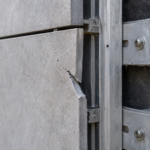
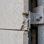
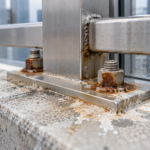
- A Chicago building had seventeen large-format porcelain panels partially disengage within 26 months despite passing all standard pull-out tests.
- North American codes treat porcelain, terracotta and stone as equivalent for attachment purposes but their failure mechanics are fundamentally different.
- Porcelain’s brittleness and thermal expansion mismatch with aluminum subframes concentrate cyclic stress at kerf edges until fatigue fracture initiates.
- No ASTM standard currently governs kerf cut quality or cyclic fatigue loading for porcelain clip systems leaving a critical gap in specification practice.
- Facade engineers must require kerf root radius documentation, eccentricity calculations and thermal movement analysis that current submittals do not include.
Porcelain Rainscreen Panels: Anchor Limits and Risk
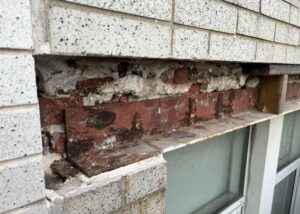
A 2021 post-occupancy inspection on a six-story mixed-use building in Chicago revealed that seventeen large-format porcelain panels had partially disengaged from their mechanical clip anchors within 26 months of installation. No panels had fallen.
But kerf edges on four units showed visible fracture propagation consistent with thermal fatigue rather than installation error. The project had passed standard pull-out testing at submittal.
The failure mode was not captured by any test in the specification package. That gap between what gets tested and what actually fails in the field is the central problem with porcelain ventilated facade systems today.
The Market Is Moving Faster Than the Standards
Large-format porcelain panels, now produced at sizes up to 1600mm x 3200mm, have arrived on commercial facades because ceramic manufacturers repositioned their product lines toward ventilated facade applications. The economics are straightforward: porcelain fabricates at lower cost than terracotta or thin stone, ships lighter and photographs well in renderings.
Architects are specifying it as a direct substitute for those legacy materials without equivalent structural review of the attachment geometry.
The North American market is absorbing this product faster than the technical framework can accommodate it. In Europe, ETAG 034 Part 1 (2012) established a specific approval guideline for kits used in external wall claddings, including mechanical attachment performance requirements calibrated to the actual failure modes of thin panel systems.
No direct ASTM or ICC equivalent exists for porcelain-specific clip attachment in North America.
IBC 2021 Section 1404.2 addresses weather-resistant exterior wall coverings but does not differentiate attachment performance requirements between ceramic, stone and porcelain panel systems. The code treats them as functionally equivalent.
They are not. The specification community is writing porcelain into projects under the same performance expectations as terracotta and the standard submittal package does not expose the difference until something moves.
What makes this substitution particularly consequential is the scale at which it is happening. Manufacturers are marketing 12mm and 14mm porcelain panels as direct drop-in replacements for 25mm to 30mm terracotta planks in clip systems originally engineered for the thicker, more ductile material.
The subframe geometry, clip spacing and kerf dimensions often carry over unchanged from the terracotta design. The panel material changes; the attachment engineering does not follow.
Facade consultants working on projects in the 2019 to 2024 construction cycle have reported receiving manufacturer submittals that reference terracotta clip system approvals as the basis for porcelain panel acceptance, with no supplemental testing or analysis to bridge the material difference. That substitution logic does not hold mechanically and no current North American code provision explicitly prohibits it.
Brittle, Stiff and Unforgiving: The Material Science Behind the Risk
Porcelain tile carries a modulus of rupture typically between 35 and 50 MPa per ANSI A137.1 Section 9. 6.
Terracotta runs 15 to 25 MPa. That numerical advantage misleads specifiers into treating porcelain as the stronger material at the anchor point.
Higher MOR means the material stores more elastic energy before fracture, not that it tolerates anchor stress better. When porcelain reaches its limit, it fails suddenly and completely.
There is no yield zone.
This matters at the kerf edge. Stone and terracotta exhibit micro-plastic deformation at bearing contact points, which distributes stress across a slightly larger area and provides a visible warning before fracture.
Porcelain offers neither. Stress concentrations at kerf cuts or anchor holes propagate directly to fracture without detectable precursor deformation.
By the time you see a crack, the failure is already in progress.
The coefficient of thermal expansion for porcelain runs approximately 6 to 8 x 10 to the negative sixth per degree Celsius. An aluminum subframe expands at roughly 23 x 10 to the negative sixth per degree Celsius.
That differential is not a minor footnote. On a dark-colored porcelain panel in Chicago, facade surface temperatures can swing 40 to 60 degrees Celsius across a single day.
The panel and the frame it clips into are moving at fundamentally different rates and the clip interface absorbs every cycle of that difference.
Water absorption below 0.5% per ANSI A137. 1 Section 9.3 Type I classification is marketed as a durability advantage.
It is also the reason porcelain cannot distribute bearing stress at anchor contact points the way stone and terracotta do. The micro-relief that allows those materials to conform slightly under load does not exist in a near-zero absorption porcelain body.
The contact stress stays concentrated exactly where the clip bears against the kerf wall.
The density of fully vitrified porcelain, typically 2,300 to 2,400 kg per cubic meter, means that large-format panels carry significant self-weight even at 12mm thickness. A 1600mm x 3200mm panel at 12mm thickness weighs approximately 140 to 150 kg.
That self-weight load path runs directly through the kerf-to-clip bearing interface on gravity clips, adding a sustained dead load component to the cyclic thermal stress that pull-out testing never combines in a single test sequence. The material’s high stiffness, with an elastic modulus around 70 GPa for dense-body porcelain, means it does not flex to redistribute that combined load.
Every kilogram of panel weight and every degree of thermal movement concentrates at the same bearing point on the kerf wall.
The Kerf Edge Is the Weakest Point Nobody Is Testing to Failure
Standard kerf cut geometry for clip-in systems runs 4 to 6mm wide and 8 to 12mm deep, cut into the panel edge. On a 12mm panel, a 10mm kerf depth removes more than 40% of the edge cross-section.
On a 20mm panel the percentage drops, but the absolute reduction in net section at the kerf root remains the governing condition for fracture initiation.
Stress concentration factors at the kerf root radius are the core mechanical problem. Sharp machine cuts in porcelain produce Kt values estimated between 2.5 and 4.
0 times nominal stress. Rounded kerf profiles reduce concentration but do not eliminate it.
The clip applies its bearing load eccentrically relative to the panel centroid, generating a moment arm at the kerf root that a simple axial pull-out test does not replicate. ASTM C648, which measures breaking strength of ceramic tile under a center-point load, gets cited as a proxy for panel strength in this application.
It is not a proxy. It tests a completely different load condition.
Fabrication variability compounds the problem. A kerf depth tolerance of plus or minus 1mm across a large-format panel introduces inconsistent load distribution across the multiple clips supporting a single panel.
The clips that land on deeper kerfs carry less bearing area and higher stress. No current ASTM standard governs kerf cut quality for porcelain facade panels.
CWCT Technical Note 69 from the Centre for Window and Cladding Technology provides kerf geometry tolerance guidance that is used as a benchmark in European practice. North American specifications have no equivalent document to reference, so fabrication tolerances are either unspecified or borrowed from stone systems where the failure mechanics differ.
The problem extends to how kerf cuts are actually made in fabrication shops. Diamond blade wet saws produce different root radii than CNC waterjet cutting and neither process is consistently controlled to a stated radius tolerance in North American fabrication practice.
A shop drawing that calls out a 5mm wide by 10mm deep kerf says nothing about root radius, surface finish inside the cut or the allowable variation in cut depth across the panel length. When a 1600mm panel carries four clips and the kerf depth varies by 1mm between the outermost and innermost cuts, the load distribution across those four clips is not equal.
Finite element analysis of representative kerf geometries conducted by European facade research groups has shown that a 1mm depth variation can shift bearing load concentration by 15 to 25% toward the shallower kerf locations, which carry the highest net section stress. That analysis exists in the European technical literature.
It has not been incorporated into any North American specification guidance document.
How Tolerance Gaps Turn Thermal Movement Into Progressive Damage
Clip-to-subframe tolerance gaps of 1 to 3mm are standard design clearance in these systems, necessary to allow installation. That clearance also allows panel micro-displacement during thermal cycling.
The displacement is not fully recovered across each cycle. This is the ratcheting mechanism and it is the reason the Chicago building’s kerf edges showed fatigue fracture at 26 months rather than installation damage at day one.
Each thermal expansion cycle loads the kerf root in bearing as the panel grows relative to the subframe. Each contraction cycle introduces a small tensile component at the clip hook as the panel tries to pull away.
The net result across hundreds of cycles is fatigue crack initiation at the kerf root. Depending on climate zone, that process plays out over three to seven years.
In ASHRAE 90.1 Climate Zone 5A, which covers Chicago, diurnal facade surface temperature swings on dark porcelain can generate an estimated 1,000 to 1,500 significant thermal cycles over five years. That is a meaningful fatigue loading history for a material with no plastic deformation capacity.
Current pull-out test protocols, whether conducted per ASTM E488 or manufacturer-specific jig tests, apply static axial load only. They do not apply cyclic loading.
They do not replicate clip geometry eccentricity. They establish peak load capacity and nothing else.
ISO 8340 provides a model for cyclic test methodology in the context of sealant tensile properties at maintained extension, demonstrating that the test methodology concept exists. No equivalent cyclic fatigue protocol has been developed for porcelain clip systems in North America.
The specification community is approving these systems based on a test that cannot see the failure mode that actually occurs.
The ratcheting mechanism is not hypothetical. Facade engineers who have examined removed panels from early-generation large-format porcelain installations in Climate Zones 4 and 5 have documented a consistent pattern: kerf walls show polished bearing surfaces from repeated clip contact, with micro-cracking initiating at the kerf root and propagating at angles consistent with combined bending and bearing stress rather than pure tension.
That fracture angle is diagnostic. A pure pull-out failure produces a different crack geometry than a fatigue failure driven by cyclic bending at the kerf root.
The Chicago inspection documented the fatigue pattern. The pull-out test that approved the system cannot produce that pattern under any load level because it does not apply the load in the direction or sequence that generates it.
Specifiers reviewing manufacturer test data have no way to identify this gap unless they understand the mechanics well enough to recognize what the test is not measuring.
What Standard Submittals Miss and What to Require Instead
The standard submittal package for a porcelain ventilated facade system typically includes manufacturer pull-out test data, panel MOR certification per ANSI A137.1 and water absorption classification. None of those documents address cyclic load behavior at the kerf interface.
A facade engineer reviewing that package has no basis to evaluate fatigue performance because the data does not exist in a form that reveals it.
Best practice, which goes beyond what IBC 2021 Section 1404.2 requires, starts with demanding kerf geometry documentation: actual cut width, depth and root radius across fabricated samples, not just nominal dimensions. Require fabrication tolerance certification with stated allowable variation and a stated consequence for out-of-tolerance panels.
Require that clip bearing stress calculations include the moment arm eccentricity at the kerf root, not just axial capacity.
If the project is in Climate Zone 4 or higher per IECC classification, require a thermal movement analysis that calculates differential displacement between panel and subframe across the full design temperature range. That calculation should drive clip gap sizing and panel joint width, not default to manufacturer minimums.
The engineer of record needs to own that number.
Beyond those baseline requirements, the submittal review process should include a specific request for the manufacturer’s stated kerf root radius and the tooling specification used to achieve it. If the manufacturer cannot provide a stated root radius with a fabrication tolerance, that gap belongs in the RFI log before panels are fabricated.
Require that a minimum of five panels from the production run be submitted for dimensional verification of kerf geometry before the balance of the order ships. That sample inspection adds minimal cost relative to the installed value of a large-format porcelain facade and provides the only field-side confirmation that the fabrication process is delivering what the shop drawings specify.
Specification language should also address panel orientation relative to clip type. Gravity clips and restraint clips carry load in different directions and the kerf geometry requirements differ between them.
A specification that calls out a single kerf dimension without distinguishing between gravity and restraint clip locations is underspecifying the system. The gravity clip location governs dead load bearing stress at the kerf wall.
The restraint clip location governs the tensile component during thermal contraction. Both conditions need to be calculated and both need to be reflected in the kerf geometry requirements for their respective locations.
Where the Specification-to-Field Gap Actually Lives
The failure mode in Chicago did not originate in the design office. It originated at the intersection of a specification that did not ask the right questions and a field installation that met every stated requirement.
The panels were cut to nominal kerf geometry. The clips were installed to the specified gap.
The pull-out tests passed. Nothing in the process was wrong by the standards that governed it.
The specification-to-field gap in porcelain ventilated facade systems is not primarily a workmanship problem. It is a test protocol problem.
The industry is using tests designed for static anchor capacity to approve systems that fail in cyclic fatigue. Until a North American equivalent to ETAG 034 addresses porcelain-specific clip attachment with cyclic loading requirements, the facade engineer carries the obligation to fill that gap through project-specific engineering rather than relying on submittal compliance alone.
Field inspection protocols need to reflect this. Post-installation inspection on large-format porcelain systems should include kerf edge examination under magnification on a statistical sample of panels, not just visual survey from grade.
Fatigue crack initiation at the kerf root is not visible from a distance. By the time it is, the failure is already advanced.
The inspection sampling methodology matters as much as the inspection method itself. A statistically meaningful sample for a facade of several hundred panels should follow acceptance sampling logic, not a fixed count.
Inspecting ten panels on a 400-panel facade represents a 2.5% sample that provides limited confidence in the population condition. A sampling plan based on ANSI/ASQ Z1.4 acceptance sampling tables, applied to kerf condition as the inspection characteristic, gives the inspection a defensible statistical basis and a defined acceptance criterion.
That approach is standard in manufacturing quality control and has direct application to facade panel inspection. It is not currently referenced in any North American facade inspection guideline for porcelain systems.
The Recommendation That the Code Has Not Yet Made
Specify a minimum kerf root radius rather than accepting whatever the fabricator delivers. A root radius of 1.5mm or greater measurably reduces stress concentration compared to a sharp cut and it is achievable with standard tooling.
Require it in the specification, verify it in the shop drawing review and confirm it on fabricated samples before panels ship.
The broader obligation falls on the technical committees that govern facade testing in North America. The absence of a cyclic fatigue test protocol for porcelain clip systems is not a minor gap.
It is the reason a building in Chicago passed every test in its specification package and still had seventeen panels partially disengage before the warranty period ended. The next failure will also pass its submittals.
ASTM Committee C21 on Ceramic Whitewares and Related Products and ASTM Committee E06 on Performance of Buildings both have scope that touches this problem, but neither has published a test standard that addresses cyclic fatigue loading at kerf clip interfaces for large-format porcelain facade panels. The technical work required to develop such a standard is not speculative.
The failure mechanics are understood. The test geometry needed to replicate field loading conditions is definable from existing clip system hardware.
What is missing is the committee action to prioritize it. ETAG 034 took the European Organisation for Technical Assessment approximately four years from initiation to publication.
A North American equivalent, developed under ASTM procedures with input from facade engineers, manufacturers and building officials, is achievable on a similar timeline if the committees treat it as a priority rather than a background item. The Chicago failure and the others that have not yet been publicly documented, represent the cost of that delay.