Fluid-Applied AWBs: Why the Smooth Promise Fails at the Seams
A forensic investigation on a four-story mixed-use building in the Mid-Atlantic region revealed that 34% of the fluid-applied AWB surface area had debonded from the OSB sheathing within 18 months of occupancy. Not at field areas.
Exclusively at window rough openings, pipe penetrations and sheathing panel joints where the installer had bridged dissimilar substrates without primer. The product carried a 10-year manufacturer warranty and had passed all required ASTM testing.
The failure pattern was invisible behind the cladding until interior moisture mapping flagged elevated readings at the floor-line framing. That building is not an outlier.
It is a pattern.
What Fluid-Applied AWBs Promise and What the Specification Often Assumes
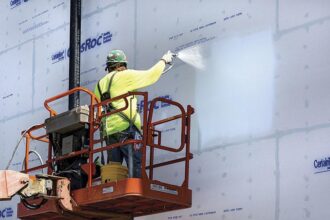
Fluid-applied AWBs are marketed as a single-layer solution meeting both air barrier performance (≤0.02 L/s·m² at 75 Pa per ASTM E2357) and water-resistive barrier requirements under IBC Section 1402. 2.
Three product categories dominate commercial specifications: vapor-permeable acrylic emulsions, vapor-impermeable self-adhering liquid membranes and hybrid silyl-terminated polymer systems. Each category carries distinct adhesion chemistry and distinct substrate sensitivity profiles.
Specifiers routinely treat them as interchangeable.
The “fluid equals continuous” assumption is embedded in most project specifications. Design documents frequently omit transition detailing at fenestration rough openings and penetrations on the premise that a fluid product self-terminates at edges without additional detailing.
That premise is wrong. Manufacturer published test data is generated on flat, clean, controlled substrates under laboratory conditions that do not replicate field assembly geometry, substrate variability or sequencing pressure.
The gap between that test data and what happens on a north-facing wall in November is where failures are born.
Acrylic emulsion products, for example, are tested on primed, conditioned substrates at 70°F and 50% relative humidity. The ASTM E2357 assembly test protocol requires a minimum 100-square-foot wall assembly with controlled joint and penetration conditions.
That protocol does not require testing at minimum application temperature, on contaminated substrates or across dissimilar substrate transitions. The qualification data in the ICC-ES evaluation report reflects those controlled conditions, not the range of conditions a product encounters across a 40,000-square-foot commercial facade.
Specifiers who read the evaluation report as a performance guarantee for field conditions are reading a document that does not make that guarantee. The product manufacturer does not claim it does.
The specification writer assumes it anyway and that assumption is the origin point of most fluid-applied AWB litigation.
Substrate Surface Preparation: The Variable That Lab Testing Eliminates
OSB arrives on site with mill glaze. Leave it exposed for six weeks and you add surface oxidation.
Frame in a building while concrete work is ongoing and you add form-release contamination. These are not edge cases; they are standard project sequencing conditions.
Most fluid-applied AWB products require substrate moisture content at or below 19% MC for wood-based substrates, but field measurement of MC before application is almost never specified as a pre-installation inspection requirement. It should be.
CMU and poured concrete substrates introduce a different failure set. Laitance and efflorescence create pH incompatibility with acrylic-based AWBs.
Published field pull-off data using ASTM D4541 shows adhesion values dropping from above 40 psi on properly prepared concrete to below 10 psi on untreated laitance surfaces. That is not a marginal reduction.
It is a failure condition that looks fine on the day of application and fails under the first hydrostatic loading event.
Gypsum sheathing presents a third failure mode. When AWB is applied over wet or damaged board, the surface paper delaminates and pulls the membrane with it.
Most manufacturers require a primed gypsum substrate and that primer requirement is routinely skipped in sequencing to recover schedule. ICC-ES AC212 establishes acceptance criteria for AWB products, but field QA protocols almost never include ASTM D4541 pull-off testing as a verification step.
The lab qualification exists. The field verification does not.
That gap is where the warranty gets voided.
The contamination problem extends beyond form-release agents. Cutting fluid residue from MEP rough-in work, overspray from spray-applied fireproofing applied to adjacent steel and concrete curing compounds applied to slab edges all create bond-inhibiting surface films that are invisible to visual inspection.
A substrate that looks clean is not necessarily a substrate that is clean. The only reliable verification method is solvent wipe testing combined with pull-off adhesion testing and neither appears in standard pre-installation inspection checklists.
ASTM D4541 Type II fixed-alignment pull-off testers are inexpensive enough that every AWB subcontractor should carry one. Most do not own one.
The specification has never required them to.
Moisture content measurement deserves equal attention. A pin-type moisture meter reading 18% MC at the OSB surface does not capture the moisture gradient through the panel.
A panel that rained on two days before application may read acceptable at the surface while carrying elevated moisture at mid-depth. That moisture migrates outward as the building dries, creating vapor pressure at the AWB bond line that produces blistering and delamination in the first post-occupancy heating season.
Specifying a minimum 24-hour dry period after precipitation, combined with moisture meter verification at a frequency of one reading per 500 square feet, adds less than two hours to a pre-installation inspection and eliminates one of the most common field failure mechanisms.
Temperature Application Windows: Where the Installation Instructions Become a Liability
Most fluid-applied AWB products publish application windows of 40°F to 95°F ambient and substrate surface temperature, with some acrylic emulsion products requiring a 50°F minimum. The distinction between air temperature and substrate surface temperature is not a fine print issue.
It is the failure mechanism.
North-facing and shaded wall conditions in IECC Climate Zones 4 through 6 routinely produce substrate surface temperatures 15°F to 25°F below ambient air temperature in winter months. An installer checking a weather app at 7:00 AM and reading 48°F is not checking the substrate.
The substrate on that north-facing wall may be reading 30°F. Application proceeds.
The product fails.
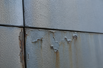
Incomplete film coalescence in acrylic emulsion products applied below minimum temperature produces a film that passes visual inspection. It looks applied.
It looks continuous. What it lacks is 30% to 50% of its design tensile bond strength, a condition that does not manifest until the assembly experiences thermal cycling or hydrostatic loading in the first heating season.
By then, the cladding is on and the pre-close inspection is a memory.
Contractor documentation practices compound this. Substrate thermometer use is rare in the field.
Temperature logs are absent from most pre-close inspection protocols. ASTM C1060 covers infrared thermography methodology that could be applied to substrate temperature verification, but it is almost never referenced in project QA plans.
The Air Barrier Association of America (ABAA) installer qualification standards address application conditions, but ABAA-certified installers remain a minority on commercial projects. When a temperature-related failure occurs and there are no temperature logs, the warranty claim becomes unresolvable.
The contractor carries the liability with no documentation to support a defense.
The upper temperature limit creates a parallel failure mode that receives less attention. At substrate surface temperatures above 95°F, acrylic emulsion products can skin over at the surface before the full film depth cures, trapping residual moisture and solvent beneath a sealed surface layer.
The resulting film has acceptable tensile strength in the upper zone and severely compromised adhesion at the substrate interface. This failure mode is most common on west-facing walls in summer months in Climate Zones 2 and 3, where afternoon substrate surface temperatures on dark-colored sheathing can reach 120°F or higher.
The installer applies the product in the morning at acceptable temperatures, the wall heats through the afternoon and the film cures under conditions that were never part of the qualification testing. Specifying a maximum substrate surface temperature limit in the construction documents and requiring infrared thermometer readings to be logged at application start and midday, converts a common failure mechanism into a manageable field variable.
Adhesion Failure Modes: A Taxonomy for Forensic Diagnosis
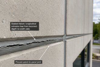
Distinguishing cohesive failure from adhesive failure is the first step in any forensic investigation of a debonded AWB. Cohesive failure occurs within the membrane body; the substrate retains a thin film of AWB material after separation.
This points toward product quality issues or over-application producing an undercured film. Adhesive failure occurs at the substrate interface, leaving the substrate surface clean.
This points toward surface preparation violations or temperature window violations. The distinction directly determines warranty responsibility and it is one that most building inspectors are not trained to make.
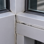
Delamination at sheathing panel joints deserves specific attention. The joint between two OSB panels is a differential movement zone.
Thermal and moisture cycling drives the panels apart and together in a repeating stress cycle. Fluid-applied products applied without mesh reinforcement at joints fail at lower strain levels than field areas because the film bridges an unsupported gap and carries the full movement load.
This is not a product deficiency. It is a detailing deficiency.
The manufacturer’s installation guide specifies mesh reinforcement at joints. The specification rarely requires it.
The installer never gets told.
Hydrostatic delamination is the failure mode that converts a small transition problem into a large field problem. Water infiltrating behind a partially bonded membrane at a transition detail pressurizes the bond line and propagates delamination laterally into field areas that were otherwise well-adhered.
ASTM E331 water penetration testing provides context for the hydrostatic pressures involved. What starts as a 6-inch debond at a window sill becomes a 4-square-foot delamination after one rain event.
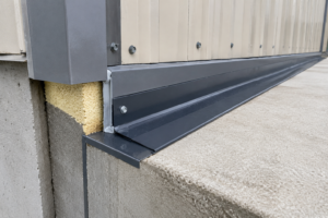
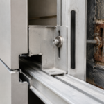
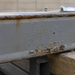
Thermal cycling fatigue at dissimilar material interfaces accumulates progressively. Metal flashing bonded to AWB membrane cycles through a larger thermal range than the membrane itself due to the flashing’s higher conductivity.
The differential movement produces a peel stress at the bond line that grows incrementally over heating and cooling seasons. This failure mode does not announce itself.
It accumulates until the bond line reaches critical strain and releases.
Recognizing these failure modes in the field requires a systematic probe and documentation protocol that most forensic investigations establish only after the litigation has started. A structured investigation protocol applied during pre-close inspections, using a combination of ASTM D4541 pull-off testing, probe-and-peel examination at transition zones and infrared thermography to identify moisture-laden delamination zones, would identify the majority of these failure modes before cladding installation.
The cost of that inspection protocol on a 40,000-square-foot facade is a fraction of the cost of one remediation mobilization. The specification almost never requires it.
Where the Continuity Assumption Breaks Down: Transitions at Openings and Penetrations
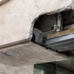
The window rough opening is a three-dimensional inside corner condition. The fluid-applied product must bridge the sheathing face, the rough sill and the framing reveal in a geometry that produces film thinning at corners and adhesion stress concentration that flat-substrate testing does not replicate.
The inside corner is where the applicator’s tool cannot maintain consistent mil thickness. Film thinning at inside corners is not installer error in the conventional sense; it is a predictable outcome of applying a fluid product into a geometry that the product’s qualification testing never addressed.
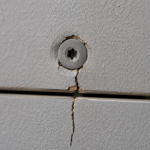
Pipe and conduit penetrations require backer rod and compatible sealant before AWB application. When AWB is applied directly over an unsupported annular gap exceeding the manufacturer’s bridging capability (typically one-quarter inch maximum), the membrane spans unsupported across the gap and fails under the first pressurization event.
This is not a rare condition. Mechanical and electrical penetrations through sheathing are routinely left to the AWB applicator to address without sequencing coordination with the MEP trades.
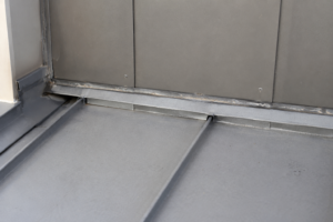
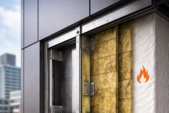
Dissimilar substrate transitions are the failure concentration point that the Mid-Atlantic investigation documented. OSB to CMU at a foundation transition, OSB to metal at a shelf angle, gypsum sheathing to OSB at a floor-line change: each transition requires a primer compatible with both substrates and a transition membrane or tape that the AWB can terminate against.
Applying fluid AWB directly across a dissimilar substrate transition without primer or transition detail produces an adhesion failure at the weaker substrate interface. The product does not bridge the chemistry difference.
No fluid product does.
The rough sill condition warrants additional attention because it concentrates three failure mechanisms simultaneously. Film thinning at the inside corner reduces membrane thickness below the manufacturer’s minimum at the exact location where water management is most critical.
The sill substrate is typically end-grain framing lumber, which has a higher moisture absorption rate than face-grain OSB and requires a different primer system. The transition from framing to sheathing at the sill corners creates a substrate discontinuity that the fluid product must bridge without mechanical support.
Specifying a pre-formed flexible flashing tape at rough sill corners, applied before the fluid AWB, provides the mechanical continuity that the fluid product cannot achieve on its own. Several manufacturers publish this as a required detail in their installation guides.
It appears in the submittal package. It is absent from the construction documents.
The installer defaults to fluid-only application because that is what the specification describes and the sill corner becomes the entry point for every subsequent moisture event.
The Specification Gap That Makes All of This Worse
The performance specification for a fluid-applied AWB on a commercial project typically references ASTM E2357 compliance, IBC Section 1402.2 and the manufacturer’s published data sheet. It almost never specifies substrate preparation requirements beyond “per manufacturer’s instructions,” field QA testing requirements referencing ASTM D4541, temperature logging protocols during application or transition detailing requirements at fenestration rough openings and penetrations.
This is a specification that sets the product up to fail and then provides no mechanism to detect the failure before close-in. The manufacturer’s data sheet contains all the required information.
The problem is that data sheet requirements are not enforceable contract documents. They are reference documents that get reviewed once during submittal and then ignored in the field.
ABAA’s Quality Assurance Program provides a third-party inspection framework that addresses application conditions, substrate preparation and transition detailing. Specifying ABAA QA on projects where fluid-applied AWBs are used is not over-engineering.
It is the minimum verification step that makes the specification enforceable. Without it, the pre-close inspection is a visual pass-fail conducted by someone who cannot see the bond line.
The CSI MasterFormat structure creates an additional gap that specification writers rarely address. AWB work typically falls in Division 07 under Section 07 27 00. Substrate preparation requirements that originate in Division 06 framing and sheathing work or in Division 03 concrete work, are not cross-referenced in the AWB section.
The result is that the framing contractor installs sheathing with no contractual obligation to coordinate with the AWB applicator on moisture content, surface cleanliness or penetration pre-treatment. The AWB applicator arrives at a substrate that was never prepared for AWB application and has no contractual authority to stop work and require remediation.
A specification that adds a cross-reference in Section 07 27 00 to substrate acceptance criteria and assigns responsibility for pre-application inspection to a named party, closes that gap at zero cost. Most specifications do not include it.
The Division 07 section writer assumes the Division 06 section writer addressed it. Neither did.
Specifying wet-film thickness verification as a contract requirement adds a second enforcement layer that costs almost nothing. A wet-film gauge costs less than twenty dollars.
Requiring the applicator to document wet-film readings at a frequency of one reading per 200 square feet, with readings recorded on a marked-up plan, creates a contemporaneous record that either confirms correct application or identifies deficient areas before close-in. Dry-film thickness can be verified after cure using a calibrated coating thickness gauge.
Neither measurement appears in standard pre-close inspection protocols. Both are standard practice in industrial coating applications where the consequences of coating failure are well understood.
What Forensic Investigations Keep Teaching Us
Every fluid-applied AWB failure investigation I have conducted over the past two decades has revealed the same pattern: the product performed as specified in the lab and failed as installed in the field. The failure was not random.
It was predictable from the detailing, the sequencing and the application conditions documented (or not documented) during construction.
The forward-looking recommendation is specific: require substrate temperature logging as a contract deliverable, specify ASTM D4541 pull-off testing at a minimum frequency of one test per 5,000 square feet with additional tests at all dissimilar substrate transitions and write transition detailing at fenestration rough openings and penetrations into the construction documents rather than delegating it to the manufacturer’s data sheet. The product is capable of performing.
The specification has to be capable of requiring the conditions under which performance is actually achievable.
The documentation requirement deserves equal weight alongside the technical requirements. A project that produces daily temperature logs, wet-film thickness records, pull-off test reports and a photographic record of transition detailing at every rough opening has created a defensible construction record.
When a moisture intrusion complaint arrives three years after occupancy, that record either confirms proper installation and redirects the investigation toward other causes or it identifies the specific application event that produced the failure and assigns responsibility accurately. Projects without that record spend the first six months of litigation arguing about what the conditions were on a Tuesday in November three years ago, with no data to resolve the dispute.
The cost of generating that documentation during construction is measured in hours. The cost of reconstructing it during litigation is measured in years.