- Exterior-grade compact HPL and interior decorative laminate are not interchangeable and confusing them causes failures within two to three seasons.
- NFPA 285 assembly compliance is required for HPL on buildings over 40 feet and must be confirmed during schematic design.
- Rainscreen cavity depth, thermal movement gaps and fastener selection are structural requirements that directly affect long-term panel performance.
- HPL’s UV stability, impact resistance and low moisture absorption give it measurable performance advantages over fiber cement in demanding climates.
- Custom digital printing and broad finish options make HPL a primary design material rather than a value-engineered substitute.
The global HPL market for exterior cladding applications is projected to exceed $1.2 billion USD by 2027, growing at a CAGR of approximately 6. 8%.
That trajectory outpaces fiber cement and EIFS in the commercial segment by a measurable margin. Yet walk into a specification meeting on a mid-rise multifamily project in any North American city and you will still hear HPL described as a “value-engineered substitute” rather than a primary design material.
That gap between market momentum and specification culture is the problem this article addresses directly.
What Exactly Is High-Pressure Laminate and Why Does It Belong on the Exterior?
HPL is produced by impregnating kraft paper layers with thermosetting resins, then bonding that core assembly under heat exceeding 1,000 psi. The result is a dense, homogeneous panel with no internal voids and no laminated face veneer that can delaminate under moisture cycling.
That manufacturing process is not a detail; it is the reason exterior HPL performs fundamentally differently from interior decorative laminate products.
The distinction between interior decorative HPL and exterior-grade compact laminate is the single most common source of specification errors I see in the field. Exterior panels run 6mm to 13mm in thickness and are engineered to resist UV degradation, freeze-thaw cycling and sustained moisture exposure.
Interior HPL is not. Specifying the wrong product class produces failures within two to three seasons.
Full stop.
Primary manufacturers active in the North American market include Trespa, Fundermax, Abet Laminati and Wilsonart Exterior, among others. Panel dimensions typically range from 4×8 to 5×12 feet depending on manufacturer, with weights running approximately 1.2 to 2.
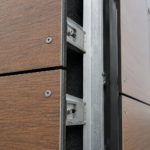
0 pounds per square foot at standard thicknesses. Attachment options include concealed clip systems, exposed mechanical fasteners and proprietary rail systems designed for specific thermal movement accommodation.
The concealed clip systems used by Trespa Meteon and Fundermax Max Exterior, for example, are engineered to allow longitudinal panel movement while maintaining positive retention against wind uplift and they are not interchangeable between manufacturers. Substituting one manufacturer’s clip into another’s rail profile is a field error that produces rattling, panel displacement and, in high-wind events, panel loss.
ANSI/NEMA LD 3 establishes the baseline performance standard for HPL, but exterior-grade panels must satisfy additional weathering and structural criteria beyond that standard. Specifiers who stop at ANSI/NEMA LD 3 compliance are not specifying exterior cladding; they are specifying interior material for an outdoor application.
The correct reference standard for exterior compact laminate is EN 438-6, which specifically addresses high-pressure decorative laminates for exterior applications and establishes requirements for weathering resistance, dimensional stability and surface integrity under sustained outdoor exposure. Several North American manufacturers publish EN 438-6 compliance data alongside domestic standards in their technical documentation.
If that data is absent from a product submittal, the submittal is incomplete and should be returned.
Performance Credentials: What the Test Data Actually Shows
The weathering performance of exterior HPL is genuinely strong and the test data supports that claim without qualification. Leading products demonstrate a color shift of less than ΔE 2.0 after 3,000-plus hours of accelerated UV exposure per ASTM G154 (fluorescent UV) and ASTM G155 (xenon arc).
For context, a ΔE below 2.0 is at or below the threshold of perceptible color change to the human eye under most viewing conditions. That is a meaningful performance benchmark, not a marketing figure.
Products in darker colorways, particularly saturated blacks and deep charcoals, warrant closer scrutiny on UV performance data because pigment loading in those formulations can affect long-term stability differently than mid-range colors. Request the actual test report, not just the summary specification sheet and confirm the tested color family matches the specified selection.
Moisture resistance follows from the manufacturing process. Compact HPL achieves water absorption rates below 1.5% per EN 438-2, which is the relevant European standard most manufacturers reference for this property.
In IECC Climate Zones 5 through 7, freeze-thaw cycling is the primary durability threat to many cladding materials. HPL’s low absorption rate means there is minimal retained moisture to expand during freeze events.
Delamination failures common in lower-density cladding materials are not a documented failure mode for properly specified compact HPL. Fiber cement panels in the same climate zones, by comparison, can absorb moisture at rates four to six times higher depending on product formulation and coating condition, which is why freeze-thaw spalling and edge degradation are recurring maintenance issues on fiber cement installations in northern markets.
HPL does not share that failure mode when the correct product class is specified.
Impact resistance is a legitimate differentiator at the ground-floor level. Compact HPL outperforms fiber cement and many composite panels in Charpy impact testing, which matters for high-traffic pedestrian zones and hail-prone regions across the central United States.
This is not a trivial advantage; ground-floor cladding replacement is expensive and disruptive. On a mixed-use project with retail at grade, the cost of replacing a 200-square-foot section of damaged fiber cement cladding, including scaffolding, color-matching and patching the water-resistive barrier, can easily exceed the material cost premium of specifying compact HPL for that zone in the first place.
Fire performance is where the conversation gets complicated and I will not soften that. HPL panels are combustible.
They carry a flame spread index that requires careful code analysis, particularly for buildings over 40 feet in height. NFPA 285 assembly testing is the governing requirement for exterior non-load-bearing wall assemblies in Types I, II, III and IV construction at that height threshold.
HPL panels used in those applications must be part of a tested and listed wall assembly. This is the most common compliance gap I encounter in HPL specifications and it is not a minor procedural issue.
An unlisted assembly on a Type I building is a code violation with significant liability exposure.
The Rainscreen Imperative: Why Attachment and Drainage Details Make or Break HPL Installations
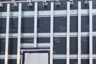
HPL panels are almost universally installed as part of a drained-and-ventilated rainscreen assembly. The pressure-equalized rainscreen principle reduces the driving force pushing water through the cladding plane by equalizing air pressure across the panel.
This extends panel service life and, more importantly, protects the water control layer behind the panel from bulk water intrusion. The panel is not the waterproofing.
The assembly is.
Minimum clear cavity depth for a functional drained and ventilated rainscreen is 3/4 inch, with 1 inch being the more defensible practice recommendation. That cavity must connect to open joints at the base and top of the assembly to allow convective drying.
Sealed cavities trap moisture and defeat the purpose of the rainscreen configuration entirely. I have seen this error on projects where the architect specified open-joint panels but the contractor sealed the base flashing detail to avoid a perceived air leakage path.
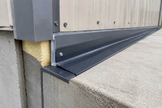
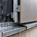
Both problems matter; you cannot solve one by creating the other. The correct solution is a through-wall flashing at the base of the assembly with weep openings at regular intervals, typically 16 to 24 inches on center, combined with a bug screen or perforated closure strip that maintains the open cavity condition without creating an uncontrolled air path into the building interior.
Continuous insulation behind the panel is now a code requirement in most jurisdictions under ASHRAE 90.1-2022 and the subframing system that supports HPL panels creates point and linear thermal bridges through that insulation layer. CI reduces thermal bridging; it does not eliminate it.
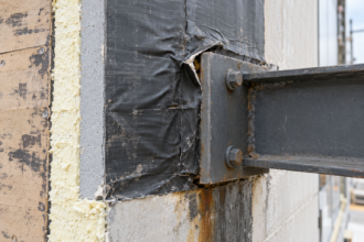
Bracket spacing, material and geometry all affect effective R-value and the difference between nominal and effective R-value at a heavily bracketed HPL assembly can exceed 30% in IECC Climate Zone 5 and colder. Thermally broken bracket systems, such as those manufactured by Halfen, Leviat and Cascadia Clip, address this by introducing a low-conductivity thermal break material between the bracket base plate and the structural substrate.
The thermal performance difference between a standard steel bracket and a thermally broken equivalent at typical spacing can represent 0.5 to 1. 5 effective R-value units per inch of insulation, which is a meaningful number when the code-required assembly R-value is already tight.
Fastener selection is not optional engineering. Coastal and high-humidity environments require stainless steel fasteners; aluminum is not adequate in salt-air exposure zones.
Manufacturer torque and spacing requirements are structural requirements, not guidelines. Thermal movement accommodation requires calculated gap sizing based on panel dimensions and local temperature differential.
A typical compact HPL panel has a coefficient of thermal expansion of approximately 0.00003 in/in/°F. On a 10-foot panel spanning a 100-degree Fahrenheit temperature differential, that is 0.036 inches of movement per panel.
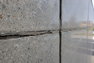
Stack that across a multi-story facade and the math matters. A 10-story building with continuous vertical panel runs and inadequate joint sizing will produce buckled panels and failed clip connections within the first two to three thermal cycles.
That failure is entirely predictable from the manufacturer’s published movement data and it happens anyway because the gap sizing calculation is treated as a suggestion rather than a design requirement.
IBC Section 1404.2 (Weather Protection) and IBC Section 1403. 2 (Water-Resistive Barrier) both apply to HPL rainscreen assemblies.
The water-resistive barrier behind the panel must be continuous and properly lapped. ASHRAE 90.1-2022 continuous insulation requirements must be coordinated with the subframing system design from the earliest stages of facade engineering, not retrofitted during construction documents.
Design Latitude: Colors, Textures and Custom Printing Capabilities
The design range available in exterior HPL is broader than most specification teams realize and that unfamiliarity contributes to the persistent “value-engineered substitute” perception. Standard palette options include solid colors across hundreds of selections, wood-grain replicas, stone and concrete textures and metallic finishes.
These are achieved through high-definition digital printing bonded into the surface layer during manufacturing, not applied as a coating that can peel or fade independently. The surface layer in exterior compact HPL is a melamine-impregnated overlay that encapsulates the printed image and bonds chemically to the phenolic core during the pressing process.
That integration is what separates the UV and abrasion performance of exterior HPL from painted or coated metal panels, where the finish system is mechanically bonded to a substrate and subject to independent degradation.
Custom digital printing now allows project-specific graphic facades, wayfinding integration and branded building skins at commercially viable quantities. This is a genuine capability shift over the past decade.
Minimum order quantities for custom graphics have dropped to ranges accessible on mid-sized institutional projects. A healthcare campus that used custom HPL panels to integrate wayfinding color coding across building exteriors or a university residence hall that reproduced archival photography at facade scale, represents the kind of application that was cost-prohibitive ten years ago and is now within reach of a standard institutional project budget.
Trespa’s TopLab Plus digital printing platform and Fundermax’s custom print program both operate at resolutions sufficient for photographic reproduction at normal viewing distances. The specification requirement for custom printed panels should include a color proof approval process with physical sample sign-off before production, because screen-to-panel color translation is not automatic and the consequences of a color mismatch on a 50,000-square-foot facade are not recoverable without full panel replacement.
The consistency advantage over natural materials is real and worth naming explicitly. HPL delivers uniform color and texture across large panel runs without the batch variation inherent in stone, brick or wood.
On a 200,000-square-foot facade, material consistency is not an aesthetic preference; it is a procurement and quality control requirement.
On the sustainability side, several manufacturers offer panels with recycled content and FSC-certified wood fiber cores. For projects pursuing LEED v4.1 BD+C certification, HPL manufacturers with published Environmental Product Declarations and Health Product Declarations support the MR Credit for Building Product Disclosure and Optimization.
Specifiers should request current EPDs and HPDs directly from manufacturers, as documentation quality varies across the product category. Some manufacturers publish third-party verified EPDs that conform to ISO 14044 and the product category rules for wood-based panels; others publish self-declared documents that do not satisfy the LEED MR credit requirements.
Confirming third-party verification status before including a product in a LEED submittal saves significant rework during the documentation phase.
Fire Code Navigation: The Compliance Conversation Specifiers Must Have Early
The fire code analysis for exterior HPL is not a task to delegate to the contractor or resolve during permit review. It must happen during schematic design, before the cladding material is committed in the owner’s budget.
The governing framework is straightforward in structure if not always in application. Buildings over 40 feet in height constructed in Types I, II, III and IV construction require exterior wall assemblies to comply with NFPA 285. HPL panels are combustible materials.
That combination means the entire wall assembly, including the HPL panel, air barrier, insulation type and thickness, framing system and any cavity components, must reflect a tested and listed configuration. Substituting insulation types or thicknesses, changing air barrier products or modifying cavity depths from the tested assembly invalidates the listing.
This is not a theoretical concern. A project I reviewed in the upper Midwest had a fully specified and code-compliant NFPA 285 assembly on the construction documents, but the contractor substituted a different continuous insulation product during procurement because the specified product had a 14-week lead time.
The substituted product had not been tested in that assembly configuration. The project was flagged during a third-party building envelope commissioning review and the resolution required either full documentation of an equivalent tested assembly or removal and replacement of the installed insulation on the affected floors.
Neither option was inexpensive.
IBC Section 1402.5 addresses combustible materials on the exterior of buildings and cross-references NFPA 285 for the applicable construction types and heights. Some jurisdictions have adopted local amendments that modify these thresholds.
The default assumption that NFPA 285 applies is the correct conservative position until local adoption is confirmed. New York City’s Building Code, for example, has historically maintained requirements that diverge from the base IBC in ways that affect exterior cladding compliance and projects in jurisdictions with active local amendments require a jurisdiction-specific code analysis rather than reliance on the base IBC framework.
The practical implication for the specification team is this: identify the NFPA 285-listed assembly first, then design the facade around it. Working in reverse, selecting HPL for design reasons and then attempting to find a compliant assembly, frequently results in either a non-compliant specification or a forced redesign of the thermal and air control layers late in design development.
The listed assemblies available from major HPL manufacturers are published in their technical documentation and are also searchable through the UL Product iQ database. Cross-referencing the manufacturer’s published assembly against the UL listing before finalizing the specification takes less than an hour and eliminates the most common compliance failure mode in HPL projects.
Type V construction below 40 feet has more flexibility, but that does not mean fire performance is irrelevant. Flame spread and smoke development indices still apply under IBC Chapter 14 and local fire marshals have authority to require additional documentation on projects where combustible cladding is proposed adjacent to egress paths or property lines.
IBC Section 1406 specifically addresses combustible cladding on buildings of all construction types and establishes flame spread index limits that apply regardless of building height. Confirming compliance with Section 1406 is a separate step from the NFPA 285 analysis and applies to a broader range of projects.
The Four Control Layers and Where HPL Specifications Routinely Fail
Specifying HPL correctly requires treating the panel as one component within an assembly that must manage all four control layers: water, air, vapor and thermal. Most HPL specification failures I have investigated trace back to a breakdown in exactly one of those layers, compounded by inadequate detailing at transitions.
The water control layer behind an HPL rainscreen must be continuous across the full facade plane including at fenestration rough openings, penetrations and transitions to adjacent cladding systems. HPL installations frequently occur on facades that also include glass curtainwall, punched windows or louvers.
The transition detail between the HPL subframing system and the fenestration frame is where water intrusion begins. A continuous water control layer that terminates at the window frame receptor without positive integration with the receptor’s drainage path will leak.
This is not a theoretical risk; it is the most common moisture intrusion failure mode I document in HPL installations. The specific failure sequence is consistent across projects: the water-resistive barrier is correctly installed on the field of the wall, the window is correctly installed with sill flashing, but the transition between the WRB termination and the window receptor relies on sealant alone rather than a lapped and mechanically fastened connection.
That sealant joint fails within three to five years of installation and the resulting water intrusion is typically attributed to the window rather than the wall assembly transition detail.
The air control layer in a rainscreen assembly is typically the air barrier applied to the substrate behind the panel. ASTM E2357 governs air barrier assembly testing and the material used must meet ASTM E2178 for material-level air permeance.
The HPL panel itself does not function as the air barrier. Treating open-joint HPL as an air control element is a fundamental misunderstanding of how the assembly works.
Open-joint HPL systems, where panel edges are left exposed without gaskets or closures, are intentionally designed to allow air movement through the cladding plane as part of the pressure-equalization strategy. The air barrier function belongs entirely to the continuous membrane or coating applied to the substrate.
Specifiers who omit a clearly defined air barrier from the HPL assembly specification or who specify an air barrier product without confirming continuity at all penetrations and transitions, are producing assemblies that will fail both energy code compliance testing and long-term moisture management performance.
Vapor control in mixed climates requires analysis, not assumption. The “vapor barrier on the warm side” rule is dangerously oversimplified for IECC Climate Zones 3 through 5 and is wrong for hot-humid zones.
The continuous insulation layer behind HPL panels affects the dew point location within the assembly and the vapor retarder class must be selected based on the actual assembly configuration, not a generic rule of thumb. In a Climate Zone 5 assembly with 3 inches of continuous mineral wool behind the HPL subframing and a steel stud cavity wall behind that, the dew point under winter design conditions typically falls within the cavity insulation or at the interior face of the continuous insulation, not at the interior wall surface.
Placing a Class I vapor retarder at the interior face of that assembly creates a moisture trap during summer cooling conditions. The correct specification in that configuration is typically a Class II or Class III vapor retarder selected based on hygrothermal modeling of the actual assembly, not a default specification carried over from a previous project in a different climate zone.
Closing: What Separates Successful HPL Projects from the Ones That End Up in Litigation
HPL performs well when it is specified correctly, detailed thoroughly and installed by trades who understand rainscreen assembly principles. That sentence contains three conditions and each one fails independently on projects I have reviewed.
The specification gap is the most preventable failure mode. Exterior compact laminate and interior decorative HPL are not interchangeable and the product data sheets make that clear to anyone who reads them.
The NFPA 285 assembly requirement is not obscure; it is in IBC Chapter 14 and in every major HPL manufacturer’s technical documentation. The thermal movement calculations are basic engineering.
These failures happen because HPL is still treated as a secondary material that does not warrant the same specification rigor as curtainwall or precast.
That treatment is no longer defensible given the scale of HPL deployment across North American commercial and multifamily construction. Specifiers who engage HPL as a primary facade material from the start of design, who run the fire code analysis in schematic design and who detail all four control layers with the same discipline applied to any other rainscreen system, will get the performance the test data promises.
Everyone else is producing the case studies that make the rest of us cautious.