

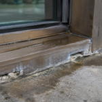
- Threshold drainage failures are the single most common finding in ground-floor commercial storefront investigations regardless of installer experience.
- The sill pocket sits at the convergence of glazing, flooring and waterproofing trades and no single party owns its drainage coordination.
- ADA’s half-inch threshold height limit creates a geometry that makes reliable gravity drainage nearly impossible without a deliberately detailed exterior apron slope.
- Increasing storm intensity in the Southeast is overwhelming threshold details that performed adequately for decades under historical precipitation loads.
- A four-component positive drainage path combined with a mandatory pre-close flood test can prevent failures that cost more than the original storefront contract.
Aluminum Storefront Threshold Drainage Failures
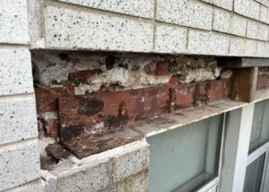
A newly completed mixed-use retail building in coastal South Carolina began showing bronze frame staining, sill extrusion corrosion and buckled luxury vinyl tile within 14 months of occupancy. The facade consultant was experienced.
The contractor installed the system per the manufacturer’s standard detail. Accessibility compliance was confirmed at certificate of occupancy.
Nobody had missed anything obvious and yet the sill pocket behind every storefront entrance had been functioning as a bathtub since day one. The exterior apron was flat.
The threshold height was 1/2 inch. The weep holes were present in the extrusion but terminated against a mortar bed with no clear path to daylight.
No single party had owned the drainage coordination. The investigation took three weeks.
The remediation took eight months and cost more than the original storefront contract.
Why the Threshold Is the Envelope’s Most Neglected Joint
The storefront threshold sits at the convergence of three trades: glazing, flooring and waterproofing. In most division-of-responsibility matrices, each trade owns the work immediately adjacent to the threshold but nobody owns the threshold condition itself.
The glazing contractor installs the sill receptor and threshold plate. The flooring contractor terminates at the interior face.
The waterproofing contractor addresses the deck or slab, not the frame pocket. The result is a joint that every trade works around and none of them details.
Unlike curtainwall sill conditions or punched window rough openings, storefront thresholds are rarely included in facade peer review scope. They get resolved at the shop drawing stage, which means the critical drainage geometry is often determined by a detailer working from a manufacturer’s standard cut sheet rather than a project-specific section developed by the architect or envelope consultant.
That detailer is optimizing for fabrication efficiency, not for site drainage geometry. The standard cut sheet assumes a competent substrate, a sloped apron and clear weep paths.
It does not verify any of them.
The visual simplicity of the condition suppresses scrutiny. A low horizontal extrusion looks like a solved problem.
It is not. The same low profile that reads as resolved on a drawing creates a drainage geometry that requires active coordination to function.
When that coordination does not happen, the extrusion becomes a dam with a label on it.
AAMA 2400-02 addresses threshold drainage only in general terms, deferring to manufacturer installation instructions for the specifics. That deference creates a coordination gap that shows up in post-occupancy investigations with regularity.
AAMA 101-17, which governs performance requirements for windows, doors and unit skylights, similarly treats field drainage as an installation variable outside the standard’s direct scope. In my experience reviewing ground-floor commercial storefront failures, threshold drainage deficiency is the single most common finding.
Not the most dramatic. The most common.
It appears in new construction and in renovation projects. It appears in buildings with experienced glazing contractors and in buildings with first-time installers.
The common variable is not installer competence. It is the absence of a project-specific drainage detail that anyone was required to follow.
Anatomy of the Aluminum Storefront Sill Pocket
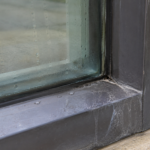
The sill pocket is the enclosed cavity formed between the aluminum sill receptor extrusion, the rough opening substrate below, the interior flooring system and the exterior threshold plate. Its geometry naturally collects water.
It has no slope to the exterior unless the installer creates one. It has no drainage outlet unless one is deliberately detailed and verified in the field.
Factory-punched weep holes exist in most sill receptor extrusions. Their presence in the extrusion profile does not mean they function.
In practice, weep holes are frequently blocked by mortar squeeze-out during frame setting, buried against a concrete slab edge or covered by sealant applied by a finisher who mistook them for gaps to be filled. Field verification of weep hole continuity to the exterior is almost never performed as a formal inspection step.
On projects where special inspections are required under IBC Chapter 17, the inspection scope typically covers structural elements, not glazing system drainage geometry. The weep hole condition falls outside every formal inspection category, which means it is verified by nobody unless the specification explicitly assigns that responsibility.
Three distinct water entry mechanisms feed the sill pocket. Wind-driven rain infiltrates past the threshold gasket, particularly under dynamic pressure loading.
Condensation accumulates on the cold aluminum sill receptor interior during heating season in mixed climates (IECC Climate Zones 3 through 5), adding a second moisture source that operates even when it is not raining. In Zone 4 mixed-humid climates, the aluminum sill receptor can sustain surface temperatures below the dew point for extended periods during winter months, producing condensate volumes that a blocked weep hole cannot discharge.
Capillary wicking from an exterior concrete apron or grade elevation at or above the sill plane provides a third, continuous source that most details ignore entirely. When all three mechanisms operate simultaneously, which they do in coastal mixed climates during shoulder seasons, the sill pocket receives water from three directions with no reliable path out.
The substrate below the sill receptor compounds the problem. In slab-on-grade construction, the sill receptor often bears directly on the concrete slab edge with a mortar bed or setting compound.
That bed fills the space between the extrusion flange and the slab, which is precisely where the weep holes need to discharge. In elevated deck construction, the sill receptor may bear on a structural topping or waterproofing assembly that has its own drainage plane, but the connection between the sill pocket drainage and that plane is almost never coordinated in the construction documents.
The two drainage systems exist in parallel without intersecting.
ASTM E2112-19, Section 7 addresses sill flashing and drainage requirements in detail. In commercial storefront applications, that standard is routinely treated as advisory.
That treatment fails in high-exposure conditions.
The ADA Threshold Height Problem
The 2010 ADA Standards for Accessible Design, Section 404.2.5 sets a maximum threshold height of 1/2 inch for exterior sliding doors and 3/4 inch for other exterior doors. IBC 2021 Section 1010.1.7 aligns with these limits at egress doors, reinforcing the low-threshold condition across both accessibility and life-safety code paths.
These limits are non-negotiable on any project subject to federal accessibility requirements, which is effectively every commercial ground-floor entrance.
The physics of drainage do not negotiate. A 1/2-inch threshold height provides insufficient head differential to drive water reliably across a sill pocket that may be 3 to 4 inches wide when the exterior apron is at or near the same elevation as the sill pocket floor.
Gravity drainage requires a continuous downward slope from water collection point to discharge point. At 1/2-inch maximum height, that slope is geometrically impossible unless the exterior apron is deliberately detailed to drop away from the building face at a meaningful rate.
In practice, exterior concrete aprons are poured by flatwork subcontractors who are working to a finish elevation at the building face and a slope specification, if one exists, that may read only “slope to drain. ” That language does not produce the geometry the threshold drainage system requires.
The ADA standard was written without explicit coordination with water management performance requirements. No ANSI or AAMA standard bridges this gap.
The accessibility compliance community and the building envelope community have not resolved this conflict and project teams are left to resolve it detail by detail. The Department of Justice, which enforces ADA Standards, has no mechanism for granting drainage-based variances to threshold height limits.
The building envelope community has no formal process for documenting the drainage penalty imposed by the 1/2-inch limit. The conflict is real, it is unresolved at the standards level and it produces failures on projects where both compliance requirements are met simultaneously.
The compounding factor is the flush interior flooring transition. Accessibility also drives the elimination of interior curbs and height changes at thresholds.
The interior curb that historically served as a secondary containment line against water that breached the threshold gasket is gone. There is no backup.
In pre-ADA commercial construction, a 1-inch interior curb at the threshold was standard practice in high-exposure zones. That curb bought time for drainage to function and contained minor infiltration events before they reached the interior flooring system.
Its removal is not a detailing oversight. It is a code requirement.
The drainage detail must compensate for the loss of that containment function entirely through the primary drainage path, which must now perform without a secondary backstop.
How Storm Intensity and Climate Exposure Are Accelerating Failures
NOAA data shows that the frequency of extreme precipitation events, defined as top 1% daily rainfall totals, has increased 37% in the Southeast United States since 1958. That increase directly raises the volumetric water load on ground-floor envelope conditions during the events most likely to drive infiltration. Details that drained adequately under historical precipitation patterns are now receiving water volumes they were not sized to handle.
In ASCE 7-22 Wind Exposure Categories C and D, wind-driven rain pressures during hurricane-track events regularly exceed the performance envelope of standard commercial storefront threshold gasket systems. Most of those gaskets are qualified under static pressure test protocols.
ASTM E331 tests water penetration resistance under uniform static air pressure differential, which does not replicate the dynamic pressure fluctuations of wind-driven rain under storm conditions. ASTM E547, which uses a cyclic pressure test protocol, comes closer to replicating real storm loading but is still a laboratory condition that does not account for gasket compression loss after years of thermal cycling, UV degradation and foot traffic deformation at the threshold plate.
The gap between the test methodology and the actual loading condition is not a minor conservatism issue. It is a fundamental mismatch.
Low-threshold designs in high-exposure zones create a condition where the margin between water entry rate and drainage capacity is effectively zero. Any weep hole blockage, whether from debris, sealant overfill or mortar, converts the sill pocket to a retention basin immediately.
The South Carolina case described at the opening of this article had all three blockage mechanisms present simultaneously. The mortar bed had sealed the weep holes at the base of the receptor.
A finisher had applied sealant across the exterior face of the extrusion as part of a joint sealing scope that was not coordinated with the glazing contractor. Windblown sand and organic debris had accumulated in the threshold plate channel within the first summer season.
The sill pocket had no functional drainage path from the day the building opened.
The service life implications extend beyond individual failure events. Aluminum sill receptor extrusions in contact with standing water in the presence of chloride ions, which are present in coastal air and in concrete curing compounds, experience accelerated galvanic corrosion at the extrusion-to-substrate interface.
The bronze anodized finish on the South Carolina frames showed visible staining within 14 months. The underlying extrusion showed measurable section loss at 36 months, which is when the remediation investigation expanded beyond the original flooring damage claim.
A detail that fails to drain does not just damage the flooring. It degrades the structural aluminum frame that supports the glazing system.
Details that performed adequately for 20 years in these climate zones are now failing within the first two years of service life. The storm intensity data explains why.
The design community has not yet recalibrated threshold detailing practice to match the new exposure reality.
Correct Drainage Detailing: The Positive Path Principle
The positive drainage path is a continuous, unobstructed, gravity-driven route from the lowest point of the sill pocket to the exterior face of the building. It relies on geometry, not on sealant continuity or gasket compression.
Those are water control layer elements that manage the primary infiltration load. Drainage handles the water that gets past them.
Conflating the two functions in a single detail is the error that produces the South Carolina outcome.
A correctly detailed threshold drainage assembly requires four components working together.
First, the sill receptor must be set with a minimum slope of 1/8 inch per foot toward the exterior. This requires either a shimmed installation or a sloped receptor extrusion.
Several major storefront manufacturers offer sloped sill receptor extrusions as a standard catalog item, but they are not the default selection and must be specified by name in Division 08. A shimmed installation using stainless steel shim stock under the interior leg of the receptor is an acceptable field alternative, but it must be shown in the construction document section with the shim thickness calculated for the receptor width. Leaving the slope method to the installer’s discretion produces inconsistent results across a multi-entrance building.
It must be specified, detailed in section and verified during installation. It will not happen by default.
Second, factory-punched weep holes must be at maximum 12-inch spacing, confirmed open at installation and protected from mortar contact during frame setting. A simple foam backer rod inserted temporarily during grouting and removed afterward is sufficient.
This step is never in the standard installation sequence. Put it in the specification.
Add a line to the Division 08 quality control requirements that reads: “Prior to frame setting, insert temporary foam backer rod in all sill receptor weep holes. Remove backer rod after mortar or grout has achieved initial set.
Confirm weep hole openings are clear before threshold plate installation. ” That language costs nothing to write.
Its absence costs the outcome described in the opening of this article.
Third, a through-wall drainage tube or weep screed must penetrate the exterior cladding or apron assembly and daylight at the exterior face with a positive drip edge. The tube must be sized for the drainage area it serves: a 3/8-inch diameter tube draining a 10-foot sill section in a high-rainfall zone is undersized.
Use 1/2-inch minimum diameter tubes at 24-inch maximum spacing in ASCE 7-22 Exposure Categories C and D. The tube material should be UV-stabilized PVC or stainless steel.
Flexible vinyl tubing degrades in UV-exposed exterior conditions and collapses under foot traffic loads if it passes through the threshold plate zone. Specify the material, the diameter and the exterior termination condition.
A drip edge formed from a stainless steel sleeve extending 3/8 inch beyond the exterior face prevents capillary wicking back into the apron joint.
Fourth, the exterior apron must slope away from the building face at a minimum of 1/4 inch per foot for at least 12 inches beyond the threshold plate. This is the detail that was missing in the South Carolina project.
The manufacturer’s standard detail assumed it. The construction documents did not show it.
The concrete subcontractor had no instruction to build it. This slope must appear on the civil or architectural site plan with a spot elevation at the building face and a slope arrow.
It must also appear in the storefront threshold section detail so the glazing contractor can confirm the condition before setting the frame. If the apron slope is not present when the frame is set, the drainage geometry of the entire assembly is compromised regardless of how well the other three components are executed.
These four components function as a system. Any single missing element degrades the whole assembly.
Field Verification: Where Correct Details Become Incorrect Installations
A correctly drawn threshold drainage detail fails at the same rate as a poorly drawn one if nobody verifies the critical dimensions during construction. The sill pocket is enclosed before the interior flooring is installed, which means the drainage path is inaccessible for inspection by the time most quality control visits occur.
The threshold plate covers the sill receptor. The interior flooring terminates at the threshold plate face.
The exterior apron is poured and finished. By the time the building is ready for occupancy inspection, every element of the drainage assembly is buried under finished work and the only way to assess it is destructive investigation or a water test that may not be in the commissioning scope.
The solution is a mandatory pre-close inspection at the sill receptor stage, before the threshold plate is installed and before interior flooring begins. This inspection should confirm sill slope with a digital level, weep hole continuity with a probe or air test, through-wall tube installation and exterior apron slope with a straightedge.
A digital level accurate to 0.1 degrees is sufficient for confirming the 1/8-inch-per-foot minimum slope requirement. A weep hole probe can be a length of 1/4-inch diameter stiff wire.
An air test using a rubber-tipped air nozzle at each weep hole confirms continuity to the exterior without requiring destructive access. None of these checks require special equipment.
All of them require that somebody has assigned responsibility for performing them.
The pre-close inspection should also include a water flood test of the sill pocket. With the threshold plate temporarily removed, introduce a controlled volume of water into the sill pocket at the high end and confirm that it exits through the weep holes and through-wall tubes within a defined time limit.
A 10-foot sill section receiving one gallon of water should show complete drainage within 60 seconds if the slope and weep hole spacing are correct. If it does not drain within that window, the blockage must be identified and cleared before the threshold plate is installed.
This test takes less than five minutes per entrance. It is the single most effective quality control step available for this condition and it is performed on essentially no projects because no specification requires it.
Specify this inspection in Division 08. Reference the specific measurements. Require a written field report with photographs of the digital level reading at the sill receptor, the weep holes confirmed clear and the through-wall tube terminations at the exterior face.
The glazing contractor will not volunteer this step. The general contractor will not enforce it unless the specification requires it.
The owner will not know it was skipped until the investigation begins.
The Coordination Gap Nobody Owns
The threshold drainage failure pattern repeats across project types, climate zones and experience levels because the condition sits in a coordination gap that the standard project delivery process does not close. The architect details the threshold height for accessibility compliance and delegates the drainage detail to the storefront shop drawings.
The storefront fabricator produces a standard detail that assumes site conditions the project may not provide. The waterproofing consultant addresses the deck membrane and terminates at the frame perimeter.
The flooring contractor installs to the interior face of the threshold plate.
The water that enters the sill pocket finds a space that every trade has finished working in and nobody is responsible for draining.
Closing that gap requires a single assigned party, typically the envelope consultant or the architect of record, to produce a project-specific threshold drainage section that coordinates all four trades before shop drawings are issued. That section must show the exterior apron slope, the through-wall drainage path, the sill receptor slope and the interior flooring termination condition in a single drawing.
It must be issued as a construction document, not resolved in submittals. When the drainage section appears only in the storefront shop drawing, it is reviewed only by the glazing contractor’s submittal reviewer, who has no authority over the concrete flatwork subcontractor or the waterproofing installer.
The section must be a contract document that all four trades are required to follow, which means it must originate in the construction document set.
The project-specific section should also identify the responsible party for each component of the drainage assembly. Assign the sill receptor slope and weep hole protection to the glazing contractor.
Assign the through-wall tube installation to the glazing contractor with coordination confirmation from the waterproofing or cladding contractor. Assign the exterior apron slope to the concrete or site contractor with a reference elevation shown on the civil drawings.
Assign the interior flooring termination height to the flooring contractor with a reference to the threshold plate top-of-frame elevation. Put all four assignments in the specification and reference the project-specific section in each Division.
When a failure occurs, the investigation will identify which assignment was not executed. Without those assignments in the contract documents, the investigation produces a finding of shared ambiguity, which resolves nothing and satisfies no one.
The next generation of threshold failures is already under construction. The projects completing today in ASCE 7-22 Exposure Category D with 1/2-inch ADA-compliant thresholds, flat exterior aprons and standard manufacturer details are the investigation files of 2026. Get ahead of it now or plan to spend time on it later under considerably less favorable conditions.