
- Structurally sealed glazing eliminates the drainage pocket that mechanically captured systems rely on to manage water at the sill.
- Specifiers routinely copy captured-system weep hole details into SSG assemblies where no drainage pocket exists to drain.
- The three-surface sill corner is the most common failure point in SSG storefront and the hardest to access after finishes close.
- An AAMA 501.2 field test before interior finishes are installed can identify sill drainage failures in an afternoon rather than years later.
- Glass replacement in SSG systems requires a 21-day cure cycle that creates real operational and liability exposure for ground-floor retail tenants.
Sealed vs. Captured Glazing: A Sill Drainage Decision
What “Sealed” and “Captured” Actually Mean in a Storefront Context
Structurally sealed glazing (SSG) bonds the glass unit to the aluminum frame using structural silicone at the perimeter. No mechanical retention element appears at the exterior sight line.
The exterior face reads as flush or near-flush glass, which is precisely why designers reach for it on ground-floor retail: it produces a clean, uninterrupted plane. Mechanically captured glazing does the opposite.
Aluminum pressure plates, stops or snap-on covers physically clamp the glazing unit into the frame pocket, with gaskets providing the primary weather seal at the glass-to-frame interface.
Both systems appear within the same product families from the same manufacturers. The framing depth, thermal break geometry and performance class can be identical.
The distinction is retention method only. That distinction carries significant consequences.
“Flush glaze” and “SSG storefront” appear interchangeably in specifications with enough frequency to constitute a specification error pattern. ASTM C1401, Standard Guide for Structural Sealant Glazing, is the governing document for SSG assembly requirements, covering cure protocols, adhesion verification and substrate preparation.
When a specification calls for flush glazing without invoking C1401 and its quality control requirements, the contractor has no defined standard to work to. The sill detail that follows will almost certainly be wrong.
What makes this error pattern persistent is that the visual difference between the two systems in a manufacturer’s catalog is minimal. Both can be specified under the same Section 08 44 13 storefront product line.
A specifier selecting a system based on an elevation rendering, without reviewing the frame section, may not recognize that the flush-glazed option shown requires a fundamentally different installation protocol and a different sill assembly. Manufacturers produce both systems because the market demands both.
The responsibility to distinguish them in the specification falls entirely on the design team and that responsibility is frequently not exercised. Glazing subcontractors bidding the work will price what the drawings show.
If the drawings show a flush exterior profile without specifying SSG and without invoking C1401, the subcontractor has no obligation to assume the more demanding installation standard applies. The result is a captured system installed where a sealed system was drawn or a sealed system installed without the quality control procedures that make it perform.
Why the Sill Condition Is Where the Two Systems Diverge Most Critically
The sill is the terminus of everything. Any water that enters the wall assembly above, migrates through the fenestration frame or bypasses the primary weather seal arrives at the sill.
Both retention systems must manage that water. They do so through fundamentally different mechanisms and that difference is rarely made explicit in the details that get built.
In a mechanically captured system, the sill frame member contains a defined drainage pocket. Weep holes or slots at the exterior face of the sill allow water that enters the glazing pocket to exit to the exterior through a pressure-equalized pathway.
The geometry of the frame creates the drainage plane. It is designed in.
In a sealed glazing system, the absence of a mechanical stop at the exterior face eliminates that pocket geometry. The silicone bond is the water control layer at the glass-to-frame interface.
If the bond is continuous and fully adhered, water does not enter the pocket because there is no pocket to enter. The sill flashing below the frame becomes the secondary control layer and its termination detail determines whether any water that bypasses the silicone has a managed exit path or a path to the interior.
Manufacturer installation details for SSG systems frequently show the sill in elevation only. The flashing termination, the relationship between the sill frame and the rough opening sill and the drainage termination point are omitted.
Contractors build what they see. When the flashing interface is not shown, it does not get coordinated.
AAMA 501.2, Quality Assurance and Diagnostic Water Leakage Field Check of Installed Storefronts, Curtain Walls and Sloped Glazing Systems, is the field test method used to locate water intrusion at the sill after installation. Running a 501.2 test during construction, before interior finishes close the sill condition, would identify drainage failures before they become tenant complaints.
Almost no one does this.
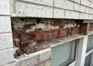
The practical consequence of that omission shows up in a specific and recurring sequence. Water enters at the sill corner, tracks along the interior face of the sill frame and appears at the interior finish some distance from the actual entry point.
The tenant reports a leak at the base of the storefront. The contractor re-caulks the exterior joint.
The leak recurs. A forensic investigation eventually locates the entry point at the sill corner, behind the silicone bond, at a location that was never accessible for inspection after the interior finish was installed.
That sequence, from first complaint to confirmed diagnosis, routinely runs six months to two years in occupied commercial space. The AAMA 501.2 test, conducted before finishes close the assembly, would have identified the failure in an afternoon.
The cost differential between a pre-finish field test and a post-occupancy forensic investigation is not close.
How Drainage Logic Differs Between the Two Systems and What Gets Assumed
Mechanically captured systems apply a two-stage defense at the glazing pocket level. Exterior gaskets function as the primary barrier.
The interior drainage plane with weep holes functions as the secondary. This is a pressure-equalized rainscreen principle operating at the frame scale.
Water that bypasses the gasket enters a managed space and exits through a designed path. The system tolerates incidental infiltration.
Sealed glazing systems do not tolerate it. The silicone bond is the primary barrier and, at the glass-to-frame interface, it is the only barrier.
There is no designed drainage pocket. Any water that bypasses the bond has no managed exit path at the sill.
It pools in the sill frame and finds the path of least resistance, which is typically the interior.
The critical assumption gap is this: specifiers and contractors routinely apply the same sill flashing and weep hole details to both systems. The weep holes specified for a captured system are transcribed directly into the SSG detail without anyone asking whether a drainage pocket exists to drain.
In an SSG sill, a weep hole in the frame face drains nothing if there is no pocket behind it collecting water. It is a feature that implies a drainage function the assembly does not have.
The specific failure mode worth naming is water migration behind the silicone bond at the sill corner. Three-surface geometry at the corner, where the sill, jamb and glass plane intersect, creates a condition where full silicone adhesion is difficult to achieve and difficult to verify.
This is a known weak point. Water that enters at that corner pools at the sill frame.
If no secondary drainage path exists and the sill flashing termination does not direct water to the exterior, it goes inside.
AAMA 501.1, the water penetration resistance test within the AAMA 501 Methods of Test for Exterior Walls suite, establishes the performance benchmark for storefront water resistance. Passing that test does not validate long-term sealant integrity at the sill corner condition.
The test applies static or dynamic pressure to the assembly as installed. It does not simulate sealant degradation, substrate movement or the three-surface corner geometry under cyclic thermal loading over time.
What the test also does not replicate is the installation variability that occurs in the field. ASTM C1401 requires that structural silicone be applied under controlled conditions, with verified substrate cleanliness, confirmed primer compatibility and documented cure time before loading.
In a shop-glazed SSG system, those conditions are achievable. In a field-glazed application, which is the condition for most ground-floor storefront, ambient temperature, humidity, substrate contamination and time pressure all work against consistent bond quality.
A glazier applying silicone at a sill corner on a cold morning, working from a lift, with a general contractor pushing for substantial completion, is not operating under the conditions the test protocol assumed. The performance grade the product carries reflects the test.
The field installation reflects the conditions. Closing that gap requires specification language that mandates field quality control procedures, not just product compliance and it requires an inspection protocol that verifies those procedures were followed before the assembly is enclosed.
The Maintenance and Replacement Access Problem Sealed Glazing Creates
In a mechanically captured system, individual glazing units can be removed from the interior or exterior by releasing the pressure plate. This is a defined, repeatable procedure.
It does not disturb adjacent sealant joints, the sill flashing or the frame geometry. A glazier can replace a single unit in a few hours.
The assembly returns to full performance immediately.
In an SSG system, glass replacement requires cutting the structural silicone bond. Cutting that bond at a sill corner disturbs the exact geometry that was already the weak point in the assembly.
Re-glazing requires full substrate preparation, new silicone application and a minimum 21-day cure period per ASTM C1401 before the unit can be loaded. That is three weeks during which the opening is boarded or temporarily sealed with a non-structural material.
For ground-floor commercial storefront, glazing replacement frequency is materially higher than upper-floor curtain wall. Vandalism, shopping cart impact, tenant fit-out damage and break-ins are not theoretical risks.
They are recurring events in retail environments. Ground-floor glazing in urban mixed-use projects gets replaced.
The question is how often and at what cost.
The specification implication is direct. If the lease places glazing replacement responsibility on the tenant, an SSG specification transfers a disproportionate maintenance burden and operational downtime to the party least equipped to manage a 21-day cure cycle.
That is a life-cycle cost variable that belongs in the system selection conversation, not in a post-occupancy dispute.
The 21-day cure window also has insurance implications that rarely surface during design. A retail tenant with a broken storefront unit operating under a temporary board-up for three weeks is carrying a security and liability exposure that their standard commercial policy may not address without a rider.
A food and beverage tenant with a boarded storefront loses customer visibility during that period. These are not abstract concerns.
A single glazing replacement event in a high-foot-traffic urban retail location can cost the tenant more in lost revenue than the glazing replacement itself. Documenting the replacement access implications of SSG in the owner-architect agreement and carrying that documentation through to the lease negotiation, is standard practice on projects where the design team has managed these claims before.
On projects where it is not documented, the first replacement event produces the conversation that should have happened during system selection. That conversation is considerably more expensive at that point.
The design team that specified SSG for aesthetic reasons, without disclosing the replacement access constraints, is in a difficult position when the building owner is looking at a three-week board-up on a ground-floor restaurant space.
Where Building Codes and Standards Currently Place the Burden
IBC Chapter 24 governs glazing in commercial construction. It addresses glazing type, safety glazing requirements and area limitations, but it does not differentiate between sealed and captured retention methods for water management performance.
The code is silent on which system is appropriate for a given sill condition. A project can comply fully with IBC Chapter 24 and still have a sill detail that fails in the first wet season.
AAMA/WDMA/CSA 101/I. S.
2/A440, the NAFS standard, establishes performance grades for fenestration products. It applies to the tested assembly under laboratory conditions.
Field conditions, particularly sill flashing interfaces and the relationship between the storefront frame and the rough opening, are outside the scope of the performance grade. A product carrying an NAFS LC40 or CW grade tells you how it performed in a test chamber.
It tells you nothing about how the sill flashing was terminated on your project.
This is the specification-to-field gap that generates most of the water intrusion claims in this category. The tested product performs.
The installed assembly does not. The difference lives in the details that no standard governs and no manufacturer shows: the flashing termination, the sill pan slope, the relationship between the storefront anchor and the water control layer and the continuity of the silicone bond at the three-surface corner condition.
Best practice, not code, requires that the specifier define the sill assembly in section and plan, not just elevation. For SSG systems specifically, the sill detail should show the flashing termination, the drainage path for any water that bypasses the silicone bond and the transition between the storefront system’s water control layer and the wall assembly’s water control layer.
If those elements are not coordinated in the construction documents, they will not be coordinated in the field.
The gap between code compliance and enclosure performance is not unique to glazing systems, but it is particularly consequential here because the code pathway gives both the design team and the contractor a defensible position that does not correspond to a performing assembly. A building official reviewing the permit set for IBC Chapter 24 compliance will confirm that the glazing type, area and safety requirements are met.
That review does not examine the sill flashing termination detail, the weep hole placement relative to the drainage pocket geometry or the transition between the storefront sill and the adjacent wall assembly’s water control layer. Those elements are outside the code review scope.
They are inside the scope of the enclosure failure that follows. ASTM E2112, Standard Practice for Installation of Exterior Windows, Doors and Skylights, provides sill pan and flashing guidance that applies to storefront rough opening conditions, but it is a voluntary standard.
Invoking it in the specification, by reference in Division 08 and by coordination requirement in the sill detail, is the mechanism that brings it into the contract. Without that invocation, it carries no contractual weight and no inspector will enforce it.
The Specification Decision That Actually Needs to Be Made
The choice between sealed and captured glazing is not an aesthetic decision with water management consequences. It is a water management decision with aesthetic consequences.
Framing it the other way around is how projects end up re-caulking exterior joints on a system that was never going to drain from the exterior.
For ground-floor commercial storefront in IECC Climate Zones 4 through 6, where bulk water management at the sill is the dominant enclosure risk, mechanically captured systems carry a meaningful performance advantage. The drainage pocket is designed.
The weep path is defined. The replacement procedure is established.
The system tolerates the incidental infiltration that will occur over a 20-year service life without routing water to the interior.
SSG systems are appropriate where the aesthetic requirement is non-negotiable and the owner understands the maintenance implications. That understanding needs to be documented.
It also requires a sill detail that compensates for the absence of a drainage pocket with a fully coordinated flashing assembly, a positive-slope sill pan and a verified transition to the wall assembly’s water control layer. Running an AAMA 501.2 field test at the sill condition before interior finishes are installed is not optional on these systems.
It is the only way to verify that the drainage logic assumed in the design actually exists in the building.
The failure pattern described at the top of this article is not a contractor error. It is a coordination failure that originates in the specification.
The contractor re-caulked because the specification implied that the exterior silicone joint was the water management strategy. It was not.
The sill was. Closing that gap between what the specification implies and what the sill detail requires is the work that prevents the callback.
Documenting the system selection rationale in the project record also matters for a reason that has nothing to do with construction administration. When a water intrusion claim surfaces two or three years after occupancy, the question that drives the liability analysis is whether the system was selected with knowledge of its constraints and whether those constraints were disclosed to the owner.
A project record that shows the design team evaluated both systems, identified the sill drainage implications of SSG, specified the compensating flashing assembly and required the AAMA 501.2 field test is a materially different document than a project record that shows SSG was specified because the elevation looked better. The first record reflects a decision.
The second reflects a preference. In a dispute, that distinction carries weight.
The specification is the document that bridges system selection and field execution. When it is written with precision about retention method, quality control requirements, sill assembly coordination and field verification, it defines a standard the contractor can meet and the owner can enforce.
When it is written as a product selection with aesthetic intent, it defines nothing the field can execute against. The water finds that gap every time.