Epoxy vs. Mechanical Anchors in Stone Facades
A 2019 forensic investigation of a mid-rise granite veneer building in downtown Toronto revealed that epoxy-anchored panels installed in the early 2000s had experienced measurable anchor displacement averaging 3: 4 mm over 15 years, well within the range associated with progressive creep failure. The building owner had specified epoxy anchors during original construction to accelerate the installation schedule by an estimated 30%, a decision that ultimately triggered a full recertification program costing seven times the original anchor budget.
This scenario is no longer an outlier. It is the pattern forensic engineers are now documenting across North American urban cores.
Anchor Selection Defines Long-Term Facade Risk
Stone veneer facades are life-safety systems. That distinction matters because the failure mode for most documented anchor deficiencies is progressive, not sudden.
A panel does not fall the day the epoxy bond begins degrading; it falls after years of incremental displacement that routine visual inspection cannot detect until the system is already compromised.
The anchor is the single load-transfer node connecting dead load, wind load and seismic demand to the building structure. Material selection at that node carries consequences that no amount of redundancy elsewhere in the assembly can offset.
Adhesive anchors transfer load through a chemical bond between epoxy, stone substrate and anchor rod. Mechanical anchors, whether kerf clips or dowel pins, transfer load through direct bearing contact between steel and stone.
The physics of those two mechanisms produce fundamentally different long-term performance profiles.
ASTM C1242, the Standard Guide for Selection, Design and Installation of Dimension Stone Attachment Systems, establishes the framework for anchor type selection based on load path and substrate condition. The central tension the standard does not resolve is this: epoxy anchoring reduces installation time significantly, while the structural performance data over 15-plus-year service lives increasingly favors mechanical systems.
Specifiers who weight schedule over performance data are making a bet the building owner may spend decades paying off.
What makes this tension operationally difficult is that the schedule argument is real. On a fast-track commercial project, eliminating the kerf-cutting operation from the stone fabrication scope can compress the cladding installation schedule by two to three weeks on a mid-rise building.
General contractors understand that number immediately. Facade engineers who recommend mechanical anchors without quantifying the long-term risk differential in terms the owner can evaluate are losing that conversation before it starts.
The engineering case for mechanical anchors needs to be made in lifecycle cost terms, not just in technical performance terms, if it is going to influence procurement decisions at the project level.
How Epoxy Anchors Work in Stone and Where the Mechanism Breaks Down
Epoxy anchors in stone rely entirely on chemical adhesion between the cured adhesive, the stone substrate and the embedded anchor rod or threaded insert. There is no mechanical interlock.
Load transfer depends on bond integrity at two interfaces: epoxy-to-stone and epoxy-to-steel. Degrade either interface and the anchor capacity degrades with it.
The first failure pathway is creep. Epoxy adhesives are viscoelastic materials; under sustained tensile or shear load they deform continuously over time rather than reaching a stable equilibrium.
This behavior accelerates above 40°C (104°F), a threshold routinely exceeded in dark granite or dark limestone facades under direct solar exposure in IECC Climate Zones 4 through 7. Studies published in the Journal of Adhesion Science and Technology document epoxy creep displacement rates of 0. 1 to 0.5 mm per year under sustained shear loads at elevated temperatures.
Cumulative displacement over 15 to 20 years approaches or exceeds the tolerance thresholds typical of stone kerf systems. The Toronto investigation cited in the opening sits precisely in that range.
The second failure pathway is chemical degradation. Moisture ingress through bore holes, freeze-thaw cycling in northern climates and alkaline leachate migrating from concrete backup walls all attack the epoxy-stone bond interface over 10 to 20 year timescales.
This is not a theoretical risk. It is a documented degradation sequence in multiple forensic investigations.
ICC-ES AC308, the Acceptance Criteria for Post-Installed Adhesive Anchors in Concrete and Masonry Elements, is the standard most specifiers cite when qualifying epoxy anchor products. The problem is that AC308 was developed for concrete substrates.
Its direct application to natural stone is an extrapolation that the acceptance criteria itself does not endorse and that many specifiers do not acknowledge in their project documentation.
Installation quality variability compounds every other risk. Mixed ratio errors, insufficient cure time, contaminated bore holes and improper embedment depth are all common field deficiencies that post-installation inspection cannot reliably detect.
The anchor looks correct from the exterior. The bond may be 40% of design capacity.
What makes the installation variability problem particularly difficult to manage is that the deficiency is invisible at the time it occurs. A kerf clip with insufficient bearing depth produces a visible geometric condition that an inspector can measure.
An epoxy anchor with a contaminated bore hole or a short pour looks identical to a properly installed anchor once the rod is set and the adhesive has cured. The only reliable detection method is destructive pull-testing and pull-testing a statistically meaningful sample of anchors on a large facade is a cost that most construction schedules do not accommodate.
The result is that installation quality variability in epoxy anchor systems is systematically underdetected during construction and only surfaces during forensic investigation years later.
Stone porosity adds another variable that AC308 does not address. Limestone, travertine and certain granites have surface porosity characteristics that affect epoxy penetration depth and bond area in ways that vary across a single panel, let alone across a facade with multiple stone lots.
A specifier relying on a manufacturer’s published pull-out values for a given epoxy product in granite is working with data generated on a specific granite specimen under laboratory conditions. The actual stone on the project may have meaningfully different surface characteristics and there is no field verification method that confirms the bond area achieved in each installed anchor.
The Mechanical Anchor Advantage: Kerf and Dowel Systems Under Load
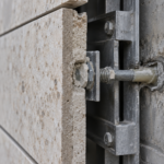
Kerf anchors transfer load through direct bearing contact between a stainless steel clip and the stone slot cut into the panel edge. No adhesive is involved.
The load path is visible, inspectable and governed by the bearing strength of the stone at the kerf face and the clip geometry. Discrete kerf clips and continuous kerf systems both follow this principle; the difference is in how distributed the bearing area is along the panel edge.
Dowel anchors transfer load through pin-bearing in drilled stone holes with defined clearance tolerances. Behavior under load is governed by stone bearing strength at the hole perimeter, not by adhesive bond integrity.
Both kerf and dowel systems accommodate thermal movement through designed slip or rotation at the connection. Epoxy anchors resist that movement and transfer thermal stress directly into the adhesive bond, adding a cyclic fatigue loading condition on top of the sustained creep load already present.
ASTM C1354, the Standard Test Method for Strength of Individual Stone Anchorages in Dimension Stone, is the primary qualification method for mechanical anchor capacity in specific stone types. It tests the actual stone-anchor interface in the actual stone species being specified.
No equivalent stone-specific test standard exists for epoxy anchor qualification in natural stone. That asymmetry in the testing framework should register as a significant red flag for any engineer doing a rigorous risk assessment.
The Indiana Limestone Institute Technical Manual, Section 4.3, establishes kerf geometry and bearing area requirements for standard clip anchor systems in limestone specifically. Long-term performance data supports the mechanical anchor approach: kerf and dowel systems installed in documented stone facades from the 1970s and 1980s remain serviceable with routine inspection.
Equivalent epoxy-anchored facades from the 1990s onward are generating the current wave of forensic investigation commissions.
The thermal movement accommodation point deserves more attention than it typically receives in specification discussions. A 30-inch granite panel installed in a northern climate will experience dimensional change of approximately 0.010 to 0.
012 inches over a seasonal temperature range of 100°F, using a coefficient of thermal expansion of approximately 4.4 x 10⁻⁶ per °F for granite. A kerf clip system with designed slip tolerance absorbs that movement without transferring stress into the anchor connection.
An epoxy anchor resists that movement and the resulting stress cycles accumulate at the bond interface over decades of seasonal cycling. The fatigue loading condition this creates is not captured in standard pull-out test data, which is generated under monotonic loading rather than cyclic loading conditions.
Specifiers who rely on static pull-out values to characterize epoxy anchor capacity in stone are working with an incomplete mechanical picture of how the anchor actually performs in service.
What the Failure Record Actually Shows
The failure pattern across North American urban cores is consistent enough now to constitute a documented trend rather than a collection of isolated incidents. High-profile stone panel detachments in Chicago in 2007 and 2012, New York findings under Local Law 11 Cycle 8 and 9 technical bulletins and the 2019 Toronto investigation have disproportionately involved adhesive anchor systems or hybrid systems where epoxy was used as a supplemental connection alongside mechanical anchors that were undersized for the full design load.
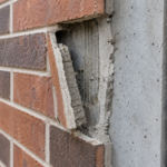
Forensic findings cluster around three failure modes. Cohesive failure within the epoxy body indicates the adhesive itself lacked the shear or tensile strength to sustain design loads over time.
Adhesive failure at the stone-epoxy interface indicates bond degradation driven by moisture, thermal cycling or chemical incompatibility. Stone substrate fracture at the bore hole edge indicates that load concentration at the anchor point exceeded the stone’s tensile capacity, often because creep displacement shifted the load path away from the intended geometry.
Each mode points to a different degradation pathway but all three are more common in adhesive systems than mechanical ones.
New York City’s Facade Inspection Safety Program (FISP) Cycle 8 and 9 technical bulletins specifically flag adhesive anchor systems as requiring enhanced documentation during facade condition assessments. The National Institute of Standards and Technology has published guidance on adhesive anchor performance variability in non-concrete substrates that reinforces the same concern.
Insurers have responded. Several major commercial property insurers now categorize epoxy-anchored stone facade systems as high-risk cladding, requiring independent engineering recertification as a condition of policy renewal.
Facade engineering firms report a measurable increase in epoxy anchor forensic investigation commissions beginning around 2018, which correlates directly with early-2000s epoxy-specified buildings reaching the 15 to 20 year service life threshold where creep accumulation becomes critical.
The hybrid system failure pattern is worth examining in more detail because it represents a specification decision that appeared conservative at the time but produced a worse outcome than either a fully mechanical or a properly engineered adhesive system would have. In several documented cases, designers specified mechanical anchors as the primary gravity support system and added epoxy anchors as supplemental lateral restraint, intending the combination to provide redundancy.
The problem is that the two anchor types have different stiffness characteristics. The mechanical anchors, with their defined bearing geometry, attracted load preferentially.
The epoxy anchors, being stiffer in the early years of service before creep accumulation, also attracted load. As the epoxy anchors crept over time, the load redistribution to the mechanical anchors exceeded the design assumption for those connections and the mechanical anchors, which had been sized for a fraction of the total load, became the limiting element.
The redundancy the designer intended became a load redistribution problem the designer had not analyzed.
The Chicago detachment events are particularly instructive because the city’s building stock includes a high concentration of dark granite cladding installed during the commercial construction boom of the late 1990s and early 2000s, precisely the period when epoxy anchoring was being widely adopted. Dark granite facades in Chicago’s climate experience surface temperatures that regularly exceed 60°C (140°F) in summer, well above the threshold at which epoxy creep rates accelerate significantly.
The combination of high service temperature, sustained dead load from panel weight and cyclic wind loading created conditions that drove creep accumulation faster than the design life assumptions embedded in the original specifications.
When Epoxy Anchoring Is Technically Defensible
Epoxy anchoring in stone is not categorically unacceptable. There are narrow conditions under which it can be specified with defensible engineering rationale and practitioners need to be precise about what those conditions actually are rather than treating them as a general permission to specify epoxy wherever it is convenient.
The strongest case for epoxy anchoring involves thin stone repair scenarios where cutting a kerf slot into an existing panel would create a net section loss exceeding the stone’s capacity or where the existing panel geometry physically cannot accommodate a mechanical anchor without replacement. In those cases, a properly qualified epoxy anchor using a product with documented creep testing data at the expected service temperature range may be the least-bad option.
The operative phrase is “least-bad,” not “preferred.
Interior stone applications with controlled temperature environments, no freeze-thaw exposure and no moisture risk represent a second defensible category. Lobby wall cladding in a conditioned space, for example, does not subject an epoxy anchor to the thermal cycling, moisture ingress or sustained elevated temperature conditions that drive the failure modes described above.
Any defensible epoxy anchor specification in stone should include: a product with ICC-ES evaluation documentation that explicitly addresses stone substrates rather than just concrete, bore hole preparation requirements that are enforceable and inspectable, minimum cure time requirements with temperature-dependent adjustment factors and a defined inspection protocol that includes torque testing of a statistically meaningful sample of installed anchors before panel installation proceeds. Without all four of those elements in the specification, the engineer is accepting liability for a system they have not actually qualified for the specific application.
The thin stone repair scenario requires additional qualification because it is the context most likely to be misapplied. A repair contractor proposing epoxy anchors for a thin stone panel that cannot accept a kerf slot is making a legitimate technical argument.
The same contractor proposing epoxy anchors for a new installation of thin stone panels because kerf cutting adds cost to the fabrication scope is making a schedule and cost argument dressed up as a technical one. The distinction matters because the specification engineer is the last line of defense against that substitution.
Repair specifications that permit epoxy anchoring should include explicit language limiting that permission to panels where mechanical anchoring is geometrically infeasible, with the determination of infeasibility requiring written engineering sign-off rather than contractor judgment in the field.
The product qualification requirement also deserves more specificity than most specifications provide. ICC-ES evaluation reports for adhesive anchor products vary significantly in the scope of testing they document.
Some reports include creep testing data at elevated temperatures; many do not. A specification that requires an ICC-ES evaluation report without specifying that the report must include creep data at the project’s expected maximum service temperature is not actually qualifying the product for the application.
The engineer needs to review the evaluation report, not just require that one exists.
Recertification Strategy for Existing Epoxy-Anchored Facades
For facade engineers currently managing an aging stone veneer building with epoxy anchors, the recertification question is not whether to investigate but how to scope the investigation efficiently. Full pull-testing of every anchor is neither practical nor necessary in most cases.
A statistically valid sampling protocol based on facade orientation, solar exposure history, stone color and original installation documentation is the appropriate starting point.
Facade orientations with the highest solar exposure and darkest stone should be sampled first and at higher density. Anchor displacement measurement using precision dial gauge surveys at accessible panels provides early evidence of creep accumulation before pull-test capacity degrades to failure threshold.
Any measured displacement exceeding 2 mm at a single anchor warrants immediate expanded investigation of the surrounding panel cluster.
The recertification scope should also address the backup wall condition. Alkaline leachate from concrete masonry backup walls is a documented contributor to epoxy-stone bond degradation and a recertification program that tests anchors without assessing the moisture and chemistry environment at the anchor-stone interface is incomplete.
Endoscopic inspection of representative bore holes, combined with pH testing of any moisture present, adds meaningful diagnostic data at low incremental cost.
Specifying mechanical anchor replacement during recertification, where panel removal is already required, eliminates the creep and chemical degradation risk for the remaining service life of the facade. The incremental cost of upgrading to a kerf or dowel system during a panel replacement operation is a fraction of the cost of a second recertification cycle ten years later.
Owners who have already paid for one forensic investigation understand this arithmetic immediately.
The sampling protocol design requires more rigor than most recertification scopes currently provide. A statistically valid sample for a facade with 500 anchor points is not 10 anchors selected by the inspector on the day of the site visit.
It is a pre-defined sample drawn from a stratified population that accounts for facade orientation, floor level, stone color and any available information about original installation conditions. The stratification matters because creep accumulation is not uniform across a facade.
South-facing panels at upper floors with dark stone will show significantly more degradation than north-facing panels at lower floors with light stone, even if both were installed on the same day with the same product and the same crew. A sampling protocol that does not account for that variability will systematically underestimate the condition of the worst-performing anchor population on the building.
Documentation recovery is a step that recertification programs frequently skip because it is time-consuming and often produces incomplete results. Original construction documents, submittals and inspection records from the installation period can identify the specific epoxy product used, the specified embedment depth and any documented installation deficiencies.
That information changes the risk profile of the investigation significantly. A building where the original submittals confirm a product with documented creep testing data and where inspection records show torque testing was performed presents a different starting risk assumption than a building where the only available documentation is the original contract drawings.
Investing two to three days in document recovery before mobilizing for field testing is almost always cost-effective relative to the alternative of scoping the investigation without that context.