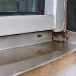
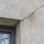
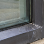
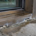
- Forensic investigation of a 1987 building found a steel lintel that had lost over 40% of its cross-sectional area at the concealed bearing pocket.
- Missing through-wall flashing and end dams allow water to pond directly against embedded steel where evaporation is nearly impossible.
- Shop-primed lintels from the 1980s and 1990s lose corrosion protection within a decade leaving bare steel in continuously wet bearing conditions.
- Effective remediation requires restoring the drainage plane with proper flashing and weep outlets before addressing the steel condition.
- Buildings from 1980 to 2000 with brick veneer and steel lintels are now at the age where concealed bearing corrosion becomes structurally significant.
Brick Soffit Lintels: Corrosion Risk and Drainage Failure
A forensic investigation on a 1987 mid-rise institutional building in the mid-Atlantic region turned up a steel lintel above a ground-floor entry that had lost more than 40% of its cross-sectional area. The corrosion was not at the exposed soffit face where any inspector with a flashlight would have seen it.
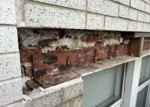
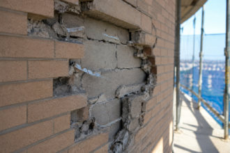
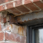
It was at the concealed bearing end, tucked into the masonry pocket where standing water had accumulated for decades with no exit path. Spalling brick above the opening was the first visible symptom, but the structural section loss had been progressing silently through at least two inspection cycles.
The detail that failed was not the coating, though the coating had also failed. It was the complete absence of through-wall flashing with a drip edge at the bearing condition.
That single omission converted a surface corrosion problem into a structural one.
Steel Lintels at Brick Soffit Conditions: The Geometry of Vulnerability
The soffit condition is geometrically hostile to steel. The lintel angle sits at the interface of two dissimilar materials where capillary moisture retention is continuous and evaporation is severely restricted.
Moisture contacts the steel on three sides simultaneously: the bearing pocket traps water against the web and bottom flange, the top flange collects water migrating down the back face of the brick wythe and the underside of the angle at the soffit face is shielded from solar drying by the brick courses above.
Unlike exposed structural steel, which experiences wetting and drying cycles that at least allow some evaporative relief, embedded lintel steel stays wet. The bearing end pocket is the worst microenvironment in the entire assembly: low air movement, direct contact with mortar and brick and no drainage path.
Mortar is alkaline when fresh and provides temporary passivation, but as carbonation proceeds over decades, that protection disappears and active corrosion accelerates.
The distinction between cosmetic surface rust at the soffit face and concealed section loss at the bearing end is not semantic. These are different failure modes with different structural implications.
Surface rust is a maintenance issue. Section loss at the bearing is a load path issue.
ASCE 7-22 requires that load paths remain continuous and that structural elements maintain adequate capacity under the applicable load combinations. A lintel that has lost 40% of its section area is not meeting that requirement regardless of how the brick above it looks from the sidewalk.
The geometry also concentrates galvanic risk. Where the steel angle bears directly on mortar without an isolating membrane, the mortar acts as an electrolyte bridging the steel and the embedded masonry ties or shelf angle anchors nearby.
In buildings where mixed metals were used, such as aluminum window frames abutting the steel lintel at the jamb condition, the galvanic potential accelerates corrosion at the steel surface in contact with the electrolyte. This condition was common in 1980s institutional construction where aluminum storefront systems were set directly into masonry openings without a thermal or galvanic break at the lintel bearing.
The result is an electrochemical cell that operates continuously as long as moisture is present, which in an unflashed bearing pocket is effectively always.
Field investigators should note that the angle leg orientation matters. A lintel installed with the vertical leg of the angle facing outward presents a larger exposed surface area to the cavity face and collects more water on the horizontal leg than a lintel oriented with the vertical leg facing inward toward the backup wythe.
Neither orientation eliminates the problem, but the outward-leg configuration consistently shows more aggressive top-flange corrosion in field assessments of same-era buildings with otherwise identical details.
How Moisture Reaches the Lintel: The Drainage Failure Sequence
Wind-driven rain penetrates the brick wythe through mortar joints, head joints, cracks and the brick-mortar interface itself. This is not a defect in well-built masonry; it is the expected behavior of a drainage wall assembly.
The design assumption is that water migrating down the back face of the brick wythe will be intercepted by through-wall flashing, directed to weep outlets and discharged to the exterior. When that sequence breaks down, water collects on the top flange of the lintel angle.
At the bearing end, the lintel is recessed into a masonry pocket. Water that reaches this zone has no outlet if through-wall flashing is absent or if flashing end dams are missing.
BIA Technical Notes 7A, Moisture Control in Brick Masonry, establishes the foundational framework for understanding this migration behavior: water follows the path of least resistance down the cavity face and accumulates at any horizontal obstruction. The lintel bearing is exactly that obstruction.
Mortar bridging at the flashing plane compounds the problem. This was a pervasive installation defect in 1980s and 1990s construction, when masons routinely allowed mortar droppings to accumulate on flashing surfaces and partially or fully block weep outlets.
Pre-2000 project details frequently omitted end dams entirely and relied on paint-grade coatings rather than hot-dip galvanizing at embedded steel. The result is a blocked drainage plane that creates a ponding condition directly against the steel bearing.
Freeze-thaw cycling then accelerates the deterioration. Water retained in the bearing pocket expands on freezing, fractures mortar joints and opens new infiltration pathways.
Each cycle widens the cracks, increases water infiltration volume and deepens the corrosion exposure. The process is self-reinforcing and it does not slow down on its own.
The rate of infiltration is not uniform across the building face. Lintels at ground-floor openings in high-exposure orientations, typically north and west elevations in the mid-Atlantic and northeast regions, accumulate moisture faster than lintels on sheltered elevations.
Prevailing wind direction during storm events drives rain at angles that maximize penetration through head joints in the courses immediately above the lintel. A building with 30 years of weather exposure on a northwest corner entry may show bearing pocket corrosion two to three times more advanced than a comparable lintel on the south elevation of the same building.
Condition assessments that sample only accessible or visible lintels without accounting for exposure orientation will systematically underreport the worst conditions in the inventory.
Cavity width also affects the drainage failure sequence. Buildings constructed with nominal 1-inch cavities, which were common in cost-driven institutional construction of this era, provide insufficient space for mortar droppings to clear the cavity without bridging.
NCMA TEK 19-2B recommends a minimum 2-inch clear cavity to reduce bridging risk, but many 1980s details show 1-inch or less. In those assemblies, mortar bridging is not an installation defect so much as a geometric inevitability and the flashing plane is compromised from the first course of brick laid above the lintel.
The Coating Specification Gap: What Was Built vs. What Was Required
The majority of lintels installed in 1980s and 1990s commercial masonry were specified as shop-primed or field-painted. These coatings have service lives of 5 to 10 years in dry exposure conditions.
In the concealed wet environment of the bearing pocket, that service life is shorter. Far shorter.
Hot-dip galvanizing per ASTM A123/A123M provides a zinc layer of 3.9 oz/ft² minimum for structural steel sections in the relevant thickness category. That zinc layer sacrificially protects the base steel even after surface damage and it provides a service life measured in decades rather than years in moderately aggressive environments.
It was rarely specified for embedded lintels in this era. The prevailing assumption was that the lintel was “protected” by the masonry enclosure.
That assumption was wrong and we are now documenting the consequences on buildings across the country.
Epoxy-based coatings and zinc-rich primers were available in the 1980s and 1990s and would have performed better than alkyd shop primer at the bearing condition. They were seldom called out in project specifications for what specifiers considered a standard lintel condition.
The coating failure timeline runs as follows: shop primer degrades within the first decade, bare steel begins active corrosion and measurable section loss appears by year 15 to 20. That is precisely the timeline now presenting in 1980s and 1990s buildings undergoing condition assessment. AISC Design Guide 3 addresses serviceability considerations including corrosion allowance for structural steel, but the guidance assumes exposure conditions are known and accounted for in the original design.
At embedded lintels, they were not.
The specification-to-field gap extended beyond coating selection. Shop drawings for lintels in this era were typically reviewed for dimensional compliance and load capacity, not for coating system verification at the bearing condition specifically.
A lintel could pass shop drawing review with an alkyd primer notation and be installed in a bearing pocket with no further scrutiny. Inspection protocols did not include coating thickness measurement at the bearing end because the bearing end was embedded in masonry by the time any inspection occurred.
The result was a systematic blind spot: the most corrosion-vulnerable location on the lintel was the least inspected location during construction.
Stainless steel lintels were available as an alternative specification in this period and were occasionally used in high-end residential and landmark institutional projects. Type 304 stainless at the lintel condition eliminates the galvanic and oxidation corrosion mechanisms entirely, though it introduces a cost premium of roughly three to five times the installed cost of a hot-dip galvanized carbon steel angle of equivalent section.
For most institutional construction budgets of the 1980s, that premium was not approved. The buildings now requiring remediation are paying a deferred cost that substantially exceeds what the stainless specification would have added to the original contract.
Reading the Symptoms: What Condition Assessment Must Document
Visible indicators at the soffit face follow a recognizable sequence. Rust staining on brick below the lintel appears first, driven by water carrying iron oxide out through the mortar joints and weep outlets.
Spalling at the outer course above the lintel follows as rust jacking generates lateral expansion pressure against the brick face. Mortar joint cracking at the bearing zone and stepped cracking in the courses above the opening indicate that the lintel has deflected or that the bearing condition has shifted.
Efflorescence patterns along the soffit face confirm active moisture migration through the assembly.
Delamination sounding of brick courses above the lintel can reveal the lateral extent of rust jacking before full spalling occurs. A simple chain drag or hammer sounding identifies hollow areas where the brick face has separated from the backup.
This is a low-cost, high-value step that should be standard practice at any lintel location showing staining or cracking.
Intrusive investigation is required to assess the bearing condition. Selective brick removal at the bearing end exposes the lintel seat, allows measurement of remaining section with calipers, documents coating condition and reveals whether through-wall flashing is present and continuous.
ICC/ASCE/SEI 11-17, Guideline for Structural Condition Assessment of Existing Buildings, provides the framework for this type of intrusive protocol, including documentation standards and the threshold criteria for structural engineer referral. ASTM C1193, Guide for Use of Joint Sealants, provides secondary reference for documenting joint condition at the soffit perimeter, which is a contributing factor in moisture infiltration at the lintel zone.
Photography must capture the bearing pocket, flashing termination or absence, weep outlet condition and any mortar bridging. This documentation drives both the repair scope and the decision to escalate to a structural engineer.
Caliper measurements at the bearing end should record the remaining section thickness at the web, the bottom flange and the top flange independently. Corrosion is not uniform across the section and the web at the bearing face typically shows the greatest loss because it sits in direct contact with mortar and receives the least air circulation of any surface on the angle.
Recording only a single measurement or estimating section loss visually without calipers produces documentation that will not support a structural engineer’s capacity calculation. The investigation report should include a scaled sketch of the bearing pocket showing the measurement locations and the as-found condition of the flashing plane, end dam and weep outlet at each investigated location.
When multiple lintels are investigated across a building, tabulating results by elevation and opening size allows the structural engineer to identify patterns and extrapolate to uninvestigated locations with similar exposure conditions.
The Deficient Detail: Anatomy of the Bearing Condition Failure
The deficient detail has a consistent geometry across dozens of buildings from this era. The lintel angle bears on masonry without a continuous through-wall flashing membrane at the bearing elevation.
There is no end dam at the termination of the flashing where it exists and there is no drip edge or kick-out at the outer face of the soffit. Each of these omissions contributes independently to the failure and their combination is catastrophic over a 30-year service period.
The absence of end dams is the most consequential omission. Even when through-wall flashing is present, an unterminated flashing allows water to migrate laterally off the end of the flashing sheet and directly into the bearing pocket.
The end dam is a simple formed metal or sealant termination that prevents this lateral migration. It costs almost nothing to install during original construction.
Retrofitting it requires removing brick, which costs significantly more.
The drip edge at the soffit face serves a separate function. Without a positive drip edge projecting beyond the brick face, water running down the soffit migrates back along the underside of the angle by surface tension and re-enters the assembly at the mortar joint.
This is a textbook capillary failure that the drip edge interrupts mechanically. The geometry requires a minimum 3/8-inch projection beyond the face of the brick to break the water film reliably.
Many installed lintels terminate flush with the brick face or are recessed slightly, providing no capillary break whatsoever.
The flashing material specification compounds the omission problem. Where through-wall flashing was installed in 1980s construction, it was frequently specified as rubberized asphalt sheet or plain bituminous membrane without a metal facing.
These materials are susceptible to puncture during brick installation and to long-term degradation from UV exposure at the exposed termination edge. Field investigation of 1980s buildings regularly finds flashing that has delaminated from the backup, torn at the drip edge and lost its lap seal integrity at splices.
A flashing membrane that has lost continuity provides no more drainage control than no flashing at all and it creates a false sense of compliance during visual inspection because the material is present even though it is no longer functional. Current practice specifies composite flashings with a metal facing bonded to a rubberized asphalt or EPDM backing, which provides puncture resistance during installation and long-term dimensional stability at the termination edge.
That specification was not standard in 1987 and the buildings from that era reflect it.
Repair Scope: What Remediation Actually Requires
Surface-applied coatings applied over existing corroded lintels without addressing the drainage geometry will fail. This approach fails because it treats the symptom while leaving the moisture source intact.
Within five to ten years, the new coating degrades in the same wet pocket environment that destroyed the original coating and the section loss continues.
Effective remediation requires addressing the water control layer first. Through-wall flashing must be installed continuously at the bearing elevation with properly formed end dams and a drip edge at the soffit face.
Weep outlets must be cleared or re-established at maximum 24-inch spacing. Only after the drainage geometry is corrected does it make sense to address the steel condition.
For lintels with section loss below the structural engineer’s threshold, hot-dip galvanized replacement lintels per ASTM A123/A123M are the appropriate specification. For lintels with section loss that compromises load path capacity under ASCE 7-22 load combinations, the structural engineer must determine whether supplemental support, full replacement or temporary shoring is required before masonry work proceeds.
Do not allow masonry contractors to proceed with repointing or brick replacement above a compromised lintel without a structural determination in hand.
The sequencing of remediation work is as important as the scope itself. Masonry contractors working from a repair drawing that shows new flashing and lintel replacement will default to removing brick, setting the new lintel and relaying brick in a single mobilization.
That sequence is correct only if the structural engineer has confirmed that the existing lintel can carry construction loads during the interim period when brick is removed and the new lintel is being set. Where section loss is advanced, temporary shoring of the masonry above the opening must be installed before any brick is removed.
The shoring loads must be transferred to the floor slab or structural frame, not to the deteriorated lintel or the adjacent masonry. A pre-construction meeting between the masonry contractor, the structural engineer of record and the building envelope consultant to confirm the shoring plan and the sequencing of brick removal is not optional on any project where section loss has been documented above 20% of the original cross-section.
Weep outlet restoration deserves specific attention in the repair scope. Mortar-blocked weeps cannot be cleared by probing alone if the blockage extends more than an inch or two into the cavity.
In those cases, removing the brick course at the weep location, clearing the flashing surface of mortar accumulation and reinstalling open-cell foam weep inserts or slotted weep tubes is the only reliable approach. Specifying weep restoration as a line item in the repair scope, rather than leaving it to the contractor’s discretion, ensures that the drainage function is actually restored rather than assumed.
What the Next Inspection Cycle Should Catch
Buildings constructed between 1980 and 2000 with brick veneer assemblies and steel lintels at fenestration heads are now at the age where concealed bearing corrosion becomes structurally significant. The window for low-cost intervention is closing.
Lintels that still have adequate section area but degraded coatings and wet bearing conditions are candidates for proactive flashing remediation and recoating. Lintels already showing spalling and rust jacking require intrusive investigation before any scope is finalized.
The inspection protocol that catches this condition before it becomes a structural referral is straightforward: document rust staining patterns at every lintel location, perform delamination sounding of the courses above the opening and flag any location where spalling or stepped cracking appears above the bearing zone for intrusive follow-up. The cost of removing two or three brick to expose the bearing seat is negligible compared to the cost of discovering 40% section loss after a partial collapse has already forced emergency shoring.
Inspection reports for buildings in this age range should include a lintel inventory table that records opening width, elevation orientation, visible distress indicators and the investigation status for each location. A building with 60 lintel locations and documented distress at 12 of them is not a building where 12 repairs are needed.
It is a building where the remaining 48 locations require a defensible basis for deferral, which means either intrusive investigation confirming adequate section or a documented engineering judgment that the uninvestigated locations share materially different exposure conditions than the distressed ones. Blanket assumptions that uninvestigated lintels are acceptable because they show no visible distress are not defensible given what is now known about the concealed nature of bearing pocket corrosion.
The visible face of the soffit is the last place this failure announces itself. By the time the brick is spalling and the rust staining is visible from the sidewalk, the structural condition at the bearing has already been deteriorating for 15 years.
The detail that failed in 1987 is still failing in buildings across the country. The question is whether the next assessment finds it before the steel does.