- A $2.3 million remediation case shows how correctly specified rainscreen assemblies still fail without proper field execution and oversight.
- Understanding the difference between drained-and-back-ventilated and true pressure-equalized systems is critical to designing effective moisture control.
- Air leakage transports 10 to 100 times more moisture into wall assemblies than vapor diffusion making air barrier continuity the top priority.
- Climate zone determines whether an assembly can dry inward or outward and choosing the wrong vapor control strategy causes moisture to accumulate year over year.
- Pre-installation inspections documented with photographs catch reversed laps and missing flashing before they become remediation costs multiplied eightfold.
Moisture Control in Rainscreen Assemblies: What the Specs Don’t Catch Before the Water Does
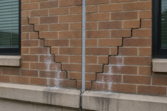
A mid-rise mixed-use building in the Pacific Northwest, completed in 2019, required full cladding removal within three years due to systemic water intrusion traced to an improperly detailed rainscreen cavity with inadequate drainage and no functional air gap. The remediation cost exceeded $2.3 million, nearly 18% of the original envelope budget.
This single case illustrates what building envelope consultants increasingly encounter: rainscreen assemblies that are specified correctly on paper but fail in execution because the people installing them never understood what the system was actually supposed to do.
What Rainscreen Assemblies Are Actually Designed to Do
The rainscreen principle rests on a two-stage defense. The cladding is the first line, shedding the bulk of precipitation before it contacts the assembly.
The water-resistive barrier and air barrier together form the second line, managing whatever water penetrates the cladding layer. Between these two lines sits the cavity and that cavity is not just a drainage plane.
It is a pressure management zone.
There is a meaningful distinction between drained-and-back-ventilated systems and true pressure-equalized rainscreen assemblies. In a pressure-equalized design, the cavity pressure is brought into equilibrium with exterior wind pressure, eliminating the driving force that pushes water inward.
This requires deliberate compartmentalization of the cavity into discrete pressure zones, with each zone sized so that the volume of air within it can respond quickly enough to pressure fluctuations at the cladding face. Without that compartmentalization, pressure equalization is a theoretical condition that never occurs in practice.
Most commercial rainscreen assemblies in North America are drained-and-back-ventilated, not pressure-equalized. Calling them pressure-equalized without the compartmentalization and sizing calculations to back it up is technically incorrect and leads to under-designed cavity openings.
The distinction has real consequences: a drained-and-back-ventilated system relies on gravity and ventilation to manage water that enters the cavity, while a true pressure-equalized system prevents that water from entering in the first place under most storm conditions.
ASTM E2273 tests drainage efficiency in EIFS assemblies but its methodology informs how we evaluate drainage performance in any cavity-based system. The test measures the percentage of water introduced at the top of an assembly that exits at the base rather than passing through to the substrate and that metric applies directly to how a rainscreen cavity should be evaluated during design review.
Rainscreen is not a barrier wall with an air gap tacked on. The distinction matters in both design intent and field execution.
A barrier wall strategy concentrates all moisture resistance in a single plane and has no recovery mechanism when that plane is breached. A rainscreen strategy accepts that water will enter the cladding layer and manages it through drainage and drying.
Treating a rainscreen as a barrier wall by sealing every joint in the cladding eliminates the pressure relief that the cavity depends on and can actually increase inward water drive by preventing pressure equalization.
The Physics of Moisture Movement in the Cavity
Three mechanisms move moisture through a rainscreen cavity: capillary action, gravity drainage and vapor diffusion. Gravity drainage is the most straightforward.
Water that enters the cavity must have an unobstructed path to exit at the base. Capillary action becomes a problem when cavity components are in direct contact, creating bridges that wick water toward the WRB surface regardless of gravity.
Vapor diffusion is the slowest mechanism and, by itself, rarely causes failures. Air leakage transports moisture orders of magnitude faster than diffusion.
Conflating the two leads to misplaced design effort, specifically the tendency to specify low-perm vapor retarders as the primary moisture control strategy while leaving air barrier transitions unaddressed.
Cavity depth directly affects both drainage efficiency and ventilation rates. A 3/8-inch cavity meets a technical minimum but performs poorly in high-rain exposure conditions.
The drainage capacity of a narrow cavity is limited by the cross-sectional area available for water flow and surface tension effects become proportionally more significant as that area decreases. A 3/4-inch to 1-inch cavity provides meaningful improvement in drainage capacity and allows sufficient air movement to support drying.
When continuous insulation fills the cavity or compresses drainage mat, effective cavity depth drops below design intent and the system fails to perform as modeled. This is a common field condition on projects where the contractor substitutes a thicker insulation product without adjusting fastener length or furring depth and the result is a cavity that exists on the drawings but not in the wall.
Pressure differentials drive bulk water intrusion. Wind-driven rain creates positive pressure on the windward face while negative pressure at corners and edges actively pulls water into gaps.
A cavity that equalizes this pressure differential reduces the driving force. A cavity that merely exists without pressure management provides drainage but not protection against inward water drive under storm conditions.
Corner conditions are particularly vulnerable because pressure coefficients at building corners are significantly higher than at field-of-wall locations. ASCE 7-22 wind pressure coefficients for components and cladding show corner zone pressures that can be two to three times the field-of-wall value, which means the same joint geometry that performs adequately at mid-wall can allow significant water entry at corners under design wind events.
Drying potential varies by climate zone. ASHRAE 160-2021 provides the hygrothermal analysis framework for evaluating whether an assembly can dry faster than it wets.
In Climate Zones 5 through 7, inward drying potential is limited for much of the year, making the cavity’s outward drying function the primary moisture relief mechanism. Designing for drying means understanding which direction the assembly can dry and in which season.
An assembly that relies on inward drying in a cold climate is depending on a mechanism that is effectively unavailable for four to six months of the year, which means any moisture that accumulates during that period must be stored without damage until drying conditions return.
Code Requirements and Standards Governing Rainscreen Performance
IBC 2021 Section 1402.2 requires weather protection for exterior walls and mandates a drainage plane behind cladding systems where water can accumulate. IRC 2021 Section R703.1 requires WRB installation behind exterior cladding with lapping and fastening sufficient to shed water.
Both provisions establish the floor, not the ceiling. Neither specifies minimum cavity depth.
Neither defines ventilation opening sizing. Code compliance does not equal adequate moisture control.
IECC 2021 continuous insulation requirements push exterior insulation thicknesses upward across Climate Zones 3 through 7. Thicker exterior insulation moves the dew point outward, which reduces condensation risk at the sheathing layer. This is beneficial.
However, it also increases cladding attachment depth, introduces thermal bridges at bracket connections and changes the effective R-value of the assembly in ways that nominal R-values do not capture. A thermally broken bracket system at 24 inches on center introduces a repeating thermal bridge that can reduce the effective R-value of a nominal R-15 continuous insulation layer by 20 to 30 percent depending on bracket geometry and conductivity.
The ASHRAE clear-field, linear thermal bridge and point thermal bridge calculation methodology in the 90.1 envelope compliance path accounts for these effects, but many specifications are written against nominal R-values without that correction applied. The result is an assembly that meets code on paper but underperforms thermally in the field and the thermal underperformance shifts the dew point back toward the sheathing layer, partially negating the condensation protection that the continuous insulation was intended to provide.
ASTM E331 and ASTM E547 test water penetration resistance under static and cyclic pressure conditions respectively. Both appear regularly in specifications for fenestration and cladding components.
Neither validates full assembly drainage performance. A window that passes ASTM E331 can still leak at the rough opening if the flashing integration is wrong.
The test evaluates the window unit in isolation, under controlled laboratory conditions, with water applied uniformly to the glazing and frame. It says nothing about what happens at the interface between the window frame and the WRB, where field-applied sealant, backer rod and flashing tape must perform together under real installation variability.
Specifiers who rely on component test compliance without full assembly detailing review are misreading what those standards actually confirm.
Code is silent on cavity ventilation opening sizing. Best practice calls for a minimum of 1/600 of the cavity face area in both inlet and outlet openings, but this is not a code requirement in any currently adopted model code edition.
The 1/600 ratio comes from research on back-ventilated facade systems and reflects the minimum opening area needed to achieve meaningful air exchange rates across the cavity height under typical wind conditions. Projects that omit this calculation entirely and rely on incidental gaps in the base track for ventilation are not meeting best practice and in high-humidity climates the drying deficit that results from inadequate ventilation accumulates over time in the sheathing layer.
Critical Detailing Failures That Compromise Moisture Control
The five failure points I encounter repeatedly are base-of-wall terminations, fenestration rough openings, penetrations through the WRB, inside corners and transitions between cladding systems. Each one represents a location where the two-stage defense is interrupted.
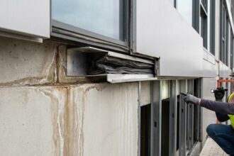
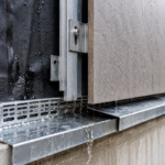
Base-of-wall terminations fail when flashing is not integrated to direct water from the cavity to the exterior. Water that drains down the WRB face must exit at the base.
When the base track, shelf angle or sill condition blocks that exit, water ponds against the WRB, saturates the drainage mat and eventually finds a path inward. The NRCA Roofing and Waterproofing Manual details base-of-wall conditions that direct water outward past the cladding face.
These details are not optional refinements; they are the mechanism by which the drainage function actually works. A common failure mode involves a continuous aluminum base track with no weep holes, installed tight to the foundation waterproofing.
The cavity drains into the track and the track has nowhere to send the water except back against the WRB. Adding weep holes at 16 inches on center in the base track costs nothing during installation and eliminates this failure mode entirely.
Doing it after cladding is installed requires removing the bottom course.
WRB lapping errors are pervasive. Shingle-lapping, where upper layers overlap lower layers, sheds water.
Face-lapping, where lower layers are installed over upper layers, creates reverse laps that channel water directly behind the WRB. I have seen face-lapped WRBs on projects where the specification explicitly required shingle-lapping.
The installer did not know the difference. This is not a rare edge case.
On one project in the mid-Atlantic region, three of five exterior walls had face-lapped horizontal seams across the full field of the WRB, installed by a crew that had applied the same product correctly on the previous project but had a different foreman on this one. Pre-installation training is not a luxury.
A 30-minute pre-installation meeting that includes a physical demonstration of correct lap direction, with the product in hand, eliminates this failure mode at a cost that is measured in hours, not dollars.
Cavity bridging by fasteners, mortar droppings or compressed insulation creates direct moisture pathways from the cavity face to the WRB surface. ASTM E2925 covers manufactured polymeric drainage and ventilation materials used to provide a rainscreen function and proper selection of drainage mat products maintains cavity depth under cladding load.
When installers compress drainage mat to accommodate fastener length, the cavity closes and the drainage mat’s function is eliminated. The correct response is to specify fastener length as a function of cladding thickness plus drainage mat thickness plus substrate penetration depth and to verify that the fastener schedule in the shop drawings matches that calculation.
Mortar droppings from masonry veneer are a separate problem that requires mortar collection devices at horizontal shelf angles, a detail that masonry subcontractors frequently omit unless it is explicitly called out in the specification and verified during installation.
Inside corners concentrate water flow and create geometry where proper lapping is difficult. The WRB must be cut and lapped at inside corners and the geometry makes it easy to create a reverse lap at the corner itself even when field laps are correctly installed.
Transitions between cladding systems, particularly at horizontal band changes, require step flashing and careful sequencing that most cladding subcontractors are not trained to execute without direct oversight. When a fiber cement panel system transitions to a metal panel system at a horizontal band, the flashing at that transition must integrate with the WRB behind both systems and direct water outward past the face of the lower cladding.
That detail requires coordination between two subcontractors who may have no contractual relationship with each other and no shared understanding of which one owns the transition condition.
Air Barrier Continuity as a Moisture Control Strategy
Air leakage is responsible for the majority of moisture accumulation in wall assemblies across North American climates. This is not a debatable point.
The physics are settled. A small gap in the air barrier at a window head allows warm, humid interior air to contact cold sheathing during winter, depositing moisture at rates that vapor diffusion could never approach.
Fixing vapor retarder placement while leaving air barrier gaps unaddressed solves the wrong problem. Research from the Building Science Corporation and the National Research Council of Canada has consistently shown that air leakage can transport 10 to 100 times more moisture into an assembly than vapor diffusion under the same boundary conditions.
A 1-inch gap in an air barrier at a window head can allow more moisture into a wall assembly in a single heating season than vapor diffusion would deliver through the entire wall area over the same period.
ASHRAE 90.1-2022 Section 5. 4.
3. 1 establishes air barrier requirements for commercial buildings, including the 0.04 cfm/ft² maximum air leakage threshold tested per ASTM E2357.
This threshold applies to the air barrier assembly, not individual components. A self-adhered membrane with excellent component performance can fail the assembly threshold if transitions at fenestration, penetrations and structural connections are not detailed and executed correctly.
The ASTM E2357 test pressurizes the full wall assembly, including all penetrations and transitions and measures total leakage across the assembly area. Projects that specify compliant air barrier materials but do not detail the transitions between those materials and adjacent assemblies routinely fail this threshold when tested.
The gap between material compliance and assembly compliance is where most air barrier failures originate.
A discontinuous air barrier also undermines the pressure-equalization function of the rainscreen cavity. If interior pressure can communicate with the cavity through air barrier gaps, the pressure differential management that the cavity is designed to provide collapses.
The cavity becomes a conduit rather than a buffer. This is particularly problematic in high-rise construction where stack effect pressures during winter can be substantial.
A 20-story building in a cold climate can develop stack effect pressures of 0.1 to 0. 2 inches of water column, which is sufficient to drive significant air movement through small gaps in the air barrier and deposit meaningful quantities of moisture in the cavity and at the WRB surface.
Material choice matters. Self-adhered membranes provide excellent continuity when properly lapped and terminated but require clean, dry substrates and temperature-appropriate adhesives.
Cold-weather installations below 40 degrees Fahrenheit require low-temperature-rated adhesive formulations and even those products require substrate priming in many conditions. Fluid-applied membranes bridge small substrate irregularities and terminate cleanly at transitions but require inspection of film thickness and coverage.
Minimum dry film thickness for most fluid-applied air barriers is 20 to 40 mils and coverage rates must be verified by wet film gauge measurement during application, not estimated from product consumption. Mechanically attached wraps are fast and forgiving but require careful seam taping and are vulnerable to puncture during cladding installation.
Drainage mat installation over a mechanically attached wrap without a protection layer is a common source of puncture damage that is invisible once the cladding is in place. All three material categories are compatible with rainscreen cavity construction.
None of them perform adequately without sequenced installation and inspection.
Climate-Specific Considerations for Rainscreen Design
ASHRAE 169-2020 defines the climate zone map that governs moisture and thermal control strategy selection. Climate Zones 4 through 6 present the most complex design conditions because inward solar vapor drive in summer and cold-weather condensation risk in winter can occur in the same assembly within the same year.
A vapor retarder that protects against winter condensation can trap moisture during summer solar drive events. Dark-colored cladding materials in these zones can reach surface temperatures of 150 to 180 degrees Fahrenheit under direct solar exposure, generating vapor pressure gradients that drive moisture inward through the assembly even when interior conditions are controlled.
Smart vapor retarders that vary permeance with relative humidity address this, but they require correct placement relative to the continuous insulation layer. A smart vapor retarder installed on the interior face of the stud cavity, inboard of continuous exterior insulation, is in the right location to respond to winter condensation risk.
The same product installed on the exterior face of the sheathing, between the sheathing and the continuous insulation, is in the wrong location and cannot respond appropriately to either winter or summer moisture drive conditions.
The Pacific Northwest and Atlantic Canada sit in high-rain exposure zones where annual precipitation and wind-driven rain indices make hygrothermal modeling standard practice, not optional analysis. The wind-driven rain index for coastal British Columbia and Washington State exceeds 100 in many locations, placing these areas in the highest exposure category under the methodology described in ASHRAE 160-2021. WUFI, as referenced in ASHRAE 160-2021, allows consultants to model time-dependent moisture accumulation and drying under actual climate data rather than simplified steady-state assumptions.
A WUFI analysis for a wood-framed wall assembly in Seattle might show that the sheathing moisture content peaks in February, drops through spring and summer and recovers to a safe level before the following winter, confirming that the assembly has adequate drying capacity. The same analysis might show that adding a low-perm WRB to that assembly eliminates the outward drying path and causes moisture content to ratchet upward year over year until failure conditions are reached.
Projects in these regions that skip hygrothermal modeling are accepting risk that the designer cannot quantify.
Hot-humid climates in Zones 1 and 2 present a different failure mode. Outward vapor drive pushes moisture from the hot exterior into the assembly.
Vapor-open WRBs allow this moisture to move through rather than accumulate. A WRB with a vapor permeance of 10 perms or greater allows moisture to pass through without resistance, preventing accumulation at the WRB surface.
Installing a low-perm WRB in Zone 2 to address vapor concerns creates a double vapor barrier condition when interior vapor control is also present, trapping moisture between two low-perm layers with no drying path. This failure mode appears on projects where a specification written for a Climate Zone 5 building is adapted for a Zone 2 project without reviewing the vapor control strategy.
The WRB product specified for the northern project may have a vapor permeance of 0.1 perms, which is appropriate for limiting inward vapor drive in a cold climate but actively harmful in a hot-humid climate where the assembly needs to dry inward.
Inspection, Quality Control and Commissioning Protocols
Pre-installation verification stops failures before they are buried behind cladding. Substrate flatness directly affects cavity depth consistency; a substrate that varies by more than 1/4 inch over 10 feet will create compressed cavity zones at high points where drainage mat is pinched between the cladding support and the WRB surface.
WRB continuity requires visual inspection of all laps, terminations and penetration seals before drainage mat and cladding installation begins. This inspection should be documented with photographs keyed to a wall elevation grid, not just a written sign-off.
Photographic documentation creates a record that is recoverable if a leak occurs after occupancy and the source needs to be traced without removing cladding. Flashing sequencing at fenestration rough openings requires sign-off by the envelope consultant before window installation proceeds.
These are not administrative checkboxes. They are the last opportunity to catch reversed laps, missing sill pans and incomplete air barrier transitions before they become remediation costs.
A sill pan that is missing on a window rough opening costs less than $50 in materials and 20 minutes of labor to install correctly before the window goes in. The same correction after the window is installed and the interior is finished costs several thousand dollars and leaves a water intrusion history in the framing that the repair cannot undo.
Field adhesion testing of self-adhered and fluid-applied air barriers should occur at a frequency tied to substrate variability and temperature conditions, not just at project start. ASTM D903 peel adhesion testing can be performed in the field with simple equipment and provides direct confirmation that the membrane is bonded to the substrate at the required strength.
A membrane that adhered correctly at 60 degrees Fahrenheit may peel at 40 degrees if the adhesive was not rated for cold-weather application. Testing at project start establishes a baseline but does not account for temperature swings during a multi-month installation.
Testing frequency should increase when ambient temperatures drop below 50 degrees Fahrenheit, when substrate moisture content is elevated or when a new lot of material is introduced to the project.
The specification-to-field gap in rainscreen construction is not a knowledge problem at the design level. It is a communication and verification problem at the construction level.
The $2.3 million remediation that opened this article was not caused by a bad specification. The WRB was specified correctly.
The cavity depth was specified correctly. The flashing details existed in the drawing set.
What failed was the assumption that a correct specification produces a correct installation without someone on site who understands why each requirement exists and has authority to stop work when it is not met. The envelope consultant on that project visited twice during the cladding installation phase.
Both visits occurred after significant portions of the WRB and drainage mat were already covered. By the time the reversed laps and missing base flashing were visible, the cost of correction had multiplied by a factor of eight compared to what it would have been if caught during installation.
Assign that person before cladding installation begins. The cost is a fraction of what comes after.