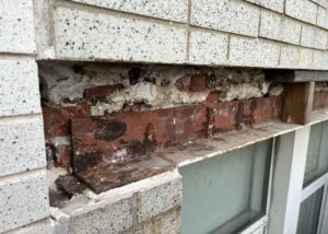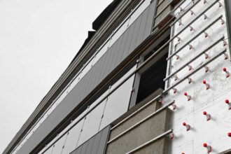
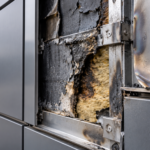
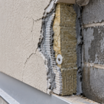
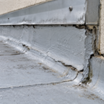
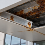

- A 3/8-inch fillet on an unprimed CMU substrate caused water infiltration across three floors eighteen months after occupancy.
- Chemical compatibility between products does not guarantee adhesion compatibility under real field conditions and substrate variability.
- Undersized fillets at 90-degree inside corners cause membranes to thin below minimum dry film thickness at the most stressed location.
- Trade sequencing gaps leave transition zones unowned, uninspected and unprotected before the overlapping contractor arrives to tie in.
- A defensible transition detail requires a dimensioned fillet, substrate-specific primers, defined overlap dimensions and mandatory inspection hold points.
Fluid Membrane Roof-to-Wall Tie-In Failures
A fluid-applied roofing membrane and a fluid-applied wall air barrier were specified by two separate consultants on a six-story mixed-use project in the mid-Atlantic region, both products from the same manufacturer, both listed as chemically compatible. Eighteen months after substantial completion, water infiltration at the parapet base had delaminated interior finishes on three floors.
The root cause was not chemistry. It was a 3/8-inch fillet radius applied over an unprimed CMU substrate at a 90-degree inside corner, installed by the roofing trade before the wall barrier crew arrived to tie in.
Why the Parapet Base Is the Most Vulnerable Node in the Fluid-Applied Assembly
The parapet base is a three-dimensional inside corner where the horizontal roof deck, the vertical wall face and often a coping or counterflashing system converge simultaneously. No other location in the exterior assembly asks a single membrane transition to manage geometry, differential movement and trade sequencing at the same time.
The stress concentration at this node is not theoretical. Thermal cycling and live-load deflection vectors from the roof deck and the wall act in opposing directions, creating chronic cyclic strain on any bridging membrane.
The roof deck wants to move horizontally. The wall resists.
The membrane at the transition absorbs the difference, every day, for the life of the building.
The organizational problem compounds the physical one. Roofing and wall air barrier scopes are routinely bid, specified and installed as separate trades with no contractually assigned owner for the transition zone.
Each trade’s specification section terminates at the boundary of its own scope. The transition detail, if it appears at all, is typically a symbolic line on an architectural drawing with no material call-out and no DFT requirement.
ASCE 7-22 Section 26.10 identifies roof-wall intersections as high-stress zones under combined wind and thermal loading. The code acknowledges the problem.
The specifications routinely do not. In practice, the gap between what the code recognizes and what the contract documents address is where water finds its path.
A building that meets every individual specification section requirement can still fail at the parapet base because the transition zone was never assigned to anyone and never detailed with enough precision to guide installation. The parapet base is not a detail that can be resolved during construction administration.
By the time the question surfaces in the field, the schedule has already made the correct answer inconvenient.
The Chemistry Compatibility Trap: Why “Same Manufacturer” Is Not a Detail
Chemical compatibility and adhesion compatibility are not the same thing. Chemical compatibility means two products will not degrade each other when in contact.
Adhesion compatibility means they will bond to each other and to the substrate under actual field conditions. Manufacturers publish compatibility matrices that address the first question.
The second question depends on substrate condition, primer selection, surface contamination and cure state at the time of tie-in.
Most manufacturer compatibility data is generated on clean, primed, laboratory-conditioned substrates. That data does not transfer to CMU with variable moisture content, concrete with form-release residue or gypsum sheathing with surface chalking from UV exposure.
The laboratory says compatible. The field says delaminated.
The primer discontinuity problem is where most transitions fail in practice. Roofing membranes and wall air barriers typically require different primers for their respective substrates.
At the transition zone, the installer may apply the roofing primer, the wall primer, both in sequence or neither, depending on which trade is responsible and what instruction they received. This is not a hypothetical.
I have documented all four conditions on the same project.
Cure-window sequencing adds another failure mode. Fluid-applied products carry defined recoat and tie-in windows.
When two trades apply products days or weeks apart, the tie-in may occur outside the manufacturer’s specified adhesion window, producing a bond that passes initial visual inspection and fails under the first thermal cycle.
ASTM D1002 governs lap shear adhesion testing. Manufacturer compatibility data is typically generated under D1002 controlled conditions.
Those conditions are not replicable in the field without a controlled environment and substrate preparation protocol that no general contractor’s schedule accommodates. A product that achieves 200 psi lap shear in a laboratory on a clean, primed, temperature-controlled substrate may achieve 40 psi on a CMU wall face that has been rained on, dried out and exposed to UV for six weeks between trade visits.
The number in the technical data sheet is not a field performance guarantee. It is a ceiling that field conditions will reduce, sometimes dramatically.
Specifiers who treat the published lap shear value as a design parameter without accounting for field degradation factors are designing to a number that the installation will never reproduce.
Fillet Geometry: The Detail That Specification Language Cannot Replace
A 90-degree inside corner is a membrane failure initiation point. Fluid-applied membranes cannot bridge a sharp inside corner without thinning to below minimum dry film thickness at the apex.
The membrane follows the geometry. At a sharp inside corner, the geometry wins.
Most fluid-applied manufacturers require a canted fillet or cant strip with a face dimension of no less than 3/4 inch at inside corners. High-movement applications, including parapet base transitions on steel-framed buildings, typically require 1.5 inches or greater.
That 3/8-inch fillet from the opening scenario was not a field error in isolation. It was the predictable result of a detail that specified a fillet without dimensioning it.
Fillet material selection matters as much as size. Hydraulic cement fillets are rigid and crack under differential movement.
Polyurethane sealant fillets accommodate movement but require surface preparation and compatibility confirmation with the overlying membrane. Membrane material fillets built up from the fluid product itself can work, but only if the installer understands that the fillet must cure before the field coat is applied and that the DFT at the fillet face must be verified independently from the field area.
Most architectural details show a symbolic fillet with no dimension, no material specification and no DFT requirement at the transition. The installer defaults to the smallest fillet that looks acceptable.
That default is the failure mode.
ASTM D6083 governs elongation and tensile requirements for liquid-applied acrylic coatings. Manufacturer published minimum DFT requirements at corners typically run 40 to 60 mils DFT, compared to 20 to 30 mils on flat field areas.
That differential exists because corners concentrate stress. A detail that does not specify corner DFT separately from field DFT is an incomplete detail.
The installer applying a uniform wet mil thickness across both the field area and the corner face is not making an error by their own understanding of the work. They are following the only instruction they received.
The specification gave them a single DFT number. They hit it.
The corner failed anyway because the required corner DFT was never written down. That is a documentation failure, not a workmanship failure and it will repeat on every project where the detail treats the corner as an extension of the field area rather than as a distinct condition with its own performance requirements.
Substrate Deflection and the Moving Target Problem
The parapet base is not a static substrate. Roof deck deflection under live load, thermal cycling and long-term creep creates a continuously moving substrate at the transition.
The membrane tie-in must accommodate this movement without delaminating from either the horizontal or vertical substrate simultaneously.
Steel deck assemblies can experience L/240 live-load deflection under IBC 2021 Section 1604.3. At a 30-foot bay, that translates to 1. 5 inches of midspan deflection.
At the parapet base, the differential movement between the deck edge and the wall face may be smaller in absolute terms but it is concentrated at a single point and it is cyclic.
How that movement is transmitted to the wall depends on the structural connection. If the parapet wall is structurally connected to the roof deck framing, deflection is shared and the transition membrane must accommodate a portion of the deck’s movement.
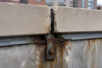
If the wall is structurally independent, which is common in CMU construction, the tie-in must bridge a true differential movement joint between two assemblies with different stiffness and different thermal mass.
Most fluid-applied transition details do not distinguish between these two conditions. The same fillet-and-membrane approach is applied to a structurally continuous steel parapet and a structurally independent CMU parapet without acknowledging that the movement demands are fundamentally different.
That failure to differentiate is a drawing problem, not a product problem.
Thermal mass differences compound the movement problem in ways that are rarely accounted for in transition details. A steel roof deck and a CMU parapet wall respond to temperature change at different rates and with different coefficients of thermal expansion.
Steel expands at approximately 6.5 millionths of an inch per inch per degree Fahrenheit. CMU expands at approximately 4.5 millionths.
Over a 100-degree Fahrenheit seasonal temperature swing, a 100-foot steel deck will move roughly 0.78 inches relative to a CMU wall of the same length. That differential accumulates at the transition zone.
A membrane tie-in that was installed at 70 degrees Fahrenheit in October is being asked to bridge a substrate that has moved a measurable distance by February. Most fluid-applied membranes have the elongation capacity to accommodate this movement if they are installed at the correct DFT and over a correctly dimensioned fillet.
The failure occurs when the DFT is marginal and the fillet is undersized, because the membrane is then operating at the edge of its elongation capacity on the first cold cycle rather than in the middle of its performance range. Designing to the middle of the performance range requires knowing what the movement demand actually is, which requires distinguishing between a structurally connected parapet and a structurally independent one.
That distinction belongs in the detail.
Application Sequencing: The Trade Coordination Failure Mode
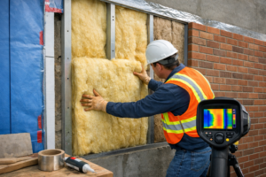
The typical sequencing conflict runs like this: the roofing contractor installs the fluid membrane and terminates at the base of the parapet. The wall air barrier contractor arrives weeks later, sometimes months later on a phased project and is expected to tie into a membrane termination edge that has been exposed to UV, foot traffic, overspray and possibly standing water.
Three failure modes appear repeatedly in this sequence. First, the roofing membrane termination edge is not protected and becomes contaminated before the wall trade arrives.
Second, the wall trade applies their primer over a cured roofing membrane without confirming that the primer is appropriate for that substrate condition, because the roofing membrane is now the substrate. Third, no one owns the overlap dimension.
The roofing membrane terminates somewhere on the wall face. The wall barrier starts somewhere on the wall face.
The two termination zones may overlap by 2 inches or by 12 inches and neither specification section defines the required overlap.
The contractual gap drives all three failure modes. When the transition zone belongs to no one, it gets detailed by no one and inspected by no one.
The building envelope consultant reviewing submittals sees two compliant submittals from two compatible products and approves both. The field condition that produces the failure never appears in a submittal.
Assign the transition zone to a single trade in the specification. Define the overlap dimension.
Require a pre-installation meeting between both trades before either one touches the parapet base. These are not extraordinary requirements.
They are the minimum conditions for a transition detail to have any chance of performing as designed.
The protection requirement for the roofing membrane termination edge is a specific and enforceable specification item that almost no project document includes. A termination edge exposed for 60 days on a mid-Atlantic project in summer will accumulate UV degradation, surface oxidation and construction dust contamination that changes the adhesion characteristics of that surface.
The wall trade arriving to tie in is not bonding to the roofing membrane as it was when it was installed. They are bonding to a weathered and contaminated version of that membrane.
Requiring the roofing contractor to install a temporary protective strip over the termination edge and requiring that strip to remain in place until the wall trade is ready to tie in, costs almost nothing and eliminates one of the three most common sequencing failure modes. The fact that this requirement appears in almost no specification section is a gap in standard practice that the industry has not closed.
What a Defensible Transition Detail Actually Contains
A transition detail that can survive field conditions requires six specific elements and most project drawings provide fewer than three.
The detail must show a dimensioned fillet with a minimum face dimension of 3/4 inch, the fillet material specified by generic type (rigid hydraulic cement, flexible polyurethane or membrane buildup) and a note that the fillet must be fully cured before the field membrane coat is applied. It must specify the primer to be used at the transition zone by substrate type, not by trade scope.
It must show the minimum overlap dimension between the roofing membrane and the wall air barrier, with 6 inches as a reasonable minimum and 12 inches preferred where the wall assembly permits. It must specify DFT requirements at the corner face separately from the field area, with 40 mils minimum DFT as the lower bound for most fluid-applied systems.
It must assign responsibility for the transition zone to a single trade or require a written joint installation protocol signed by both subcontractors. And it must require a pre-final inspection of the transition zone before cladding or coping installation conceals it.
None of these elements require a new product category or a specification innovation. They require a detail that treats the transition as a distinct condition rather than a boundary line between two other people’s scopes.
The primer specification by substrate type rather than by trade scope is the element most frequently missing and most consequential when absent. At the parapet base, the substrates present at the transition zone may include cured fluid roofing membrane, CMU, concrete masonry mortar joints, embedded metal angle and gypsum sheathing, all within a 12-inch vertical span.
Each of those substrates has a different primer requirement. A specification that says “apply primer per manufacturer’s instructions” without identifying which primer applies to which substrate at the transition zone is not a specification.
It is a delegation of the design decision to the installer, who will make that decision based on what is in their truck. Naming the primer by product designation or by generic chemistry type for each substrate condition at the transition is a one-line addition to the detail note that eliminates a failure mode that shows up repeatedly in post-occupancy investigations.
The Inspection Gap That Seals the Failure In
The parapet base transition is one of the most difficult locations to inspect after installation because it is among the first to be concealed. Coping systems, counterflashing and cladding attachment typically cover the transition zone before the building reaches substantial completion.
By the time the owner takes possession, the membrane condition at the parapet base is invisible.
This sequencing reality means that the only effective inspection window is during installation. A building envelope consultant who is not present during fluid membrane application at the parapet base is not providing enclosure quality assurance.
They are providing document review with a site visit schedule that guarantees they will never see the condition that fails.
Specify inspection hold points in the specification. Require wet mil gauge readings at the fillet face, documented with photographs, before the overlapping trade begins work.
Require substrate preparation documentation, including primer type, coverage rate and cure time, before membrane application at the transition. These requirements add a half-day of inspector time per floor.
They cost a fraction of the remediation bill that follows an undocumented transition failure eighteen months after occupancy.
The wet mil gauge reading requirement is specific enough to be enforceable and simple enough that any installer can comply with it. A notched wet film gauge costs less than five dollars.
Requiring the installer to take readings at the fillet face, at the corner apex and at 6 inches onto both the horizontal and vertical substrates and to photograph those readings before the next coat is applied, creates a contemporaneous record of the DFT condition at the transition. That record is the difference between a defensible warranty claim and a three-year dispute over what the membrane thickness actually was at the location that failed.
The photograph requirement matters because wet mil readings taken without photographic documentation of the measurement location are not verifiable after the fact. An inspector reviewing a log of wet mil readings with no location photographs cannot confirm that any of those readings were taken at the transition zone rather than on the open field area where hitting the target is easy.
The industry is installing fluid-applied systems at parapet bases faster than it is developing the inspection protocols to verify them. The next generation of envelope failures is already curing in place on projects under construction right now.
The drawings say compatible. The inspector was not there.
The fillet was 3/8 inch.