
- Forensic investigators routinely misdiagnose coping failures by focusing on sealant while missing end dam and cleat deficiencies below the coping pan.
- Oversized coping sections cause thermal ratcheting that pulls sealant from substrates, a condition no sealant replacement can permanently fix.
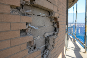
- Undersized end dams allow wind-driven water to bypass the coping face entirely, saturating insulation and corroding structural decking over time.
- Galvanic incompatibility between cleat and coping metals accelerates hidden corrosion that can release the coping under wind load within years.
- A mandatory pre-installation conference with project-specific values for section lengths, cleat spacing and end dam height prevents the most costly failures.
Bent Sheet Metal Copings: Where They Actually Fail
During a post-storm forensic investigation on a five-story concrete masonry unit building in the Mid-Atlantic region, the investigator photographs intact sealant joints at every coping lap and declares the sheet metal system “not the source. ” Six months later, destructive investigation reveals saturated rigid insulation and corroded steel deck.
The water entry traced entirely to an undersized end dam at a parapet corner that had been allowing wind-driven water to bypass the coping face by traveling laterally along the cleat plane. The sealant never failed.
The geometry did.
The Misdiagnosis Problem: Why Investigators Keep Getting Coping Failures Wrong
Visual inspection bias is the first problem. Forensic investigators default to sealant as the failure mode because sealant is the most visible component and the most commonly specified maintenance item in any building envelope management program.
When a lap joint looks intact, the coping system gets cleared. That finding is wrong more often than the industry acknowledges.
Intact sealant at lap joints creates a false-negative finding. Water entry at cleats, end dams and anchor penetrations is not visible from the roof surface without probing or destructive investigation.
The investigator who walks the parapet cap and photographs sealant condition has evaluated perhaps 20 percent of the system’s failure risk. The remaining 80 percent sits below the coping pan, behind the end dams and at the cleat-to-substrate interface where no camera angle from the roof surface reaches without deliberate probing.
The chain-of-custody problem compounds the misdiagnosis in litigation contexts. Once sealant is blamed, the actual geometric deficiencies go unrepaired.
The building leaks again after remediation. The second round of litigation is more expensive than the first would have been if the geometry had been correctly identified initially.
In one commercial office project in northern Virginia, three successive remediation scopes replaced sealant at lap joints across a 400-linear-foot parapet run. Each scope cost between $18,000 and $24,000. The fourth investigation, which included destructive removal of coping sections at three locations, identified undersized end dams and overlong aluminum sections as the governing failure mechanisms.
Neither had been touched in the prior three scopes. The total remediation cost after correct diagnosis was less than the second sealant replacement alone.
The central argument here is direct: coping failures are a systems geometry problem, not a materials problem. SMACNA’s Architectural Sheet Metal Manual, 7th Edition, establishes joint design hierarchy as the governing framework for coping performance.
That hierarchy puts geometry first. Sealant is a secondary defense, not a primary one.
Treating it as the primary defense is not a conservative approach. It is an incorrect one.
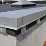
How a Bent Sheet Metal Coping System Actually Works
A coping assembly serves three simultaneous functions: it sheds water off the parapet top, resists wind uplift at the building’s highest and most exposed horizontal surface and accommodates thermal movement across temperature differentials that routinely exceed 150 degrees Fahrenheit on dark-coated metal in southern climates. Failing at any one of these functions compromises the other two.
Three primary water pathways must be blocked. Vertical face penetration through fastener holes or open joints is the obvious one.
Lateral migration under the coping pan along the cleat plane is the one investigators miss. End-to-end capillary travel through lap joints is the one sealant is actually designed to address.
Thermal movement is not a minor consideration. Aluminum expands at 0.0000128 inches per inch per degree Fahrenheit.
A 20-foot aluminum coping run experiences nearly 3/8 inch of total movement across a 150-degree surface temperature differential. That is not a rounding error.
It is a design load. Galvanized steel expands at 0.0000065 inches per inch per degree Fahrenheit, roughly half the aluminum rate, which is why section length limits differ between the two materials in SMACNA’s recommendations.
Copper expands at 0.0000094 inches per inch per degree Fahrenheit, placing it between the two. Each material requires its own section length calculation and substituting one metal for another mid-project without recalculating joint spacing is a specification failure that appears in field conditions more frequently than design teams anticipate.
This is why joint spacing, cleat design and end dam geometry are load-bearing decisions. SMACNA’s Table 1-1 in the 7th Edition documents thermal expansion coefficients by metal type precisely because these values must drive section length and joint configuration choices.
ASCE 7-22 wind uplift requirements provide the parallel load case for cleat attachment design. Both load cases must be satisfied simultaneously.
Neither is optional. A coping system designed only for thermal movement without verification against ASCE 7-22 Section 26.10 wind pressure coefficients for parapet surfaces is half-designed.
The parapet top is among the highest-pressure zones on any low-slope roof assembly and the wind load case routinely governs cleat spacing on buildings above two stories in Exposure Category C or D terrain.
Joint Spacing Failures: The Expansion Gap That Becomes an Infiltration Gap
SMACNA recommends maximum coping section lengths of 10 feet for aluminum and 10 to 12 feet for galvanized steel. Field installations routinely exceed these limits, particularly on prefabricated systems delivered in longer stock lengths where the contractor treats the stock length as the installation length.
This is a specification-to-field gap that appears on almost every project where I have performed destructive investigation. The economics driving it are straightforward: cutting stock lengths to SMACNA-compliant dimensions generates scrap and adds labor.
Without a pre-installation conference that addresses section lengths as a discrete line item, the installer defaults to the path of least material waste.
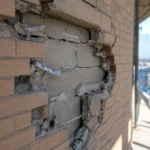
What happens when sections are too long is predictable and progressive. Thermal ratcheting opens lap joints beyond the sealant’s elongation capacity over multiple seasonal cycles, even when the sealant was correctly installed at time of construction.
ASTM C920 classifies sealant elongation performance and even a Class 50 sealant cannot compensate for a joint that is cycling three times its designed movement range. The sealant does not fail cohesively.
It debonds from one substrate while remaining intact on the other.
That forensic indicator is critical. Sealant that is cohesively intact but has pulled cleanly from one substrate is thermal pull-out, not sealant degradation.
The distinction matters enormously for repair scope and for litigation positioning. Replacing the sealant without correcting the section length solves nothing.
The replacement sealant will pull from the same substrate within two to three seasonal cycles for the same reason the original sealant did. Documenting this pattern in a forensic report requires noting both the cohesive condition of the sealant bead and the substrate from which it separated.
Adhesion failure on the metal substrate with cohesive integrity intact is the signature finding of thermal overload, not material deficiency.
The distinction between slip joints and fixed lap joints is equally important. Slip joints are designed to accommodate movement; fixed laps are not.
Misapplying fixed laps on long runs is a primary failure mechanism that appears in projects across every climate zone. SMACNA Chapter 4 in the 7th Edition addresses slip joint configurations specifically for this reason.
A slip joint allows one coping section to slide over the adjacent section through a defined range of movement without transferring stress to the sealant bead. The sealant in a correctly configured slip joint is a weather seal, not a structural bond.
Specifying slip joints in the contract documents and then accepting shop drawings that show fixed laps because the elevation view looks similar is a review failure with direct field consequences.
The field condition that accelerates all of this: installers compress expansion gaps at installation to make sections fit the run length, eliminating the designed movement allowance entirely on the first day of service. The assembly is thermally overloaded from day one.
A gap that should be 3/8 inch gets compressed to 1/16 inch because the last section in a run is 1/4 inch too long and the installer forces it into place rather than cutting it to length. That condition is not detectable from a visual inspection of the installed coping.
It requires measurement of the actual gap width at each joint against the designed gap dimension from the approved shop drawing.
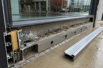
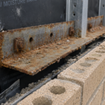
Cleat Attachment Failures: The Hidden Leak Path Nobody Photographs
Every cleat fastener is a penetration through the waterproofing plane. This is the fundamental tension in cleat design: the component that holds the coping down also creates the path through which water can enter if the attachment geometry is wrong or the fastener degrades.
The cleat is not a secondary component. It is the primary structural connection between the coping pan and the parapet and its failure mode is bulk water entry, not gradual seepage.
Two cleat failure modes dominate field investigation. The first is fastener pull-through under wind uplift cycling.
Repeated negative pressure events work fasteners through oversized or degraded substrate material, opening the coping pan and allowing bulk water entry that looks nothing like a sealant failure on the roof surface. The second is inadequate cleat engagement depth, which allows the coping to lift at the leading edge during negative pressure events without fully detaching.
The coping springs back when the wind load releases, but it has pumped water under the pan with each cycle. This pumping action is most aggressive at building corners where wind pressure coefficients are highest under ASCE 7-22 and where the coping geometry changes direction, creating additional stress concentration at the cleat nearest the corner.
Galvanic incompatibility failures are underreported. Galvanized steel cleats fastened with stainless screws into aluminum coping systems create an accelerated corrosion condition at the cleat-to-coping interface.
ASTM B117 salt spray testing data makes clear that this condition progresses rapidly in coastal exposures, often reaching section loss within five to seven years. The failure is invisible until the cleat loses enough section to release the coping under load.
Specifying cleat material to match the coping metal or specifying an appropriate isolating barrier between dissimilar metals, is a detail that disappears between the specification section and the shop drawing review with regularity. The specification may call for compatible metals.
The shop drawing may show a generic cleat without material designation. The installed condition may be whatever the sheet metal subcontractor had in stock.
Each handoff is a point where the galvanic compatibility requirement can be lost.
SMACNA Chapter 4 in the 7th Edition provides maximum cleat spacing recommendations, but these are not always cross-referenced against project-specific wind uplift calculations per ASCE 7-22 Section 26.10. In hurricane-adjacent coastal zones and high-plains wind exposure categories, the SMACNA defaults are not conservative enough without that cross-reference.
A project in Exposure Category D terrain with a basic wind speed of 130 mph requires cleat spacing and gauge verification against calculated uplift pressures, not simply compliance with SMACNA’s general recommendations. The two calculations should be performed together and the more restrictive result should govern.
The forensic indicator for cleat engagement failure is simple. A coping section that can be manually lifted more than 1/4 inch at the outer edge without fastener resistance has already failed its primary attachment function.
This test takes 10 seconds per section and requires no tools. It is the single most informative physical test available during a parapet coping investigation and it is performed on fewer than half the investigations I have reviewed in litigation support contexts.
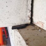
End Dam Geometry: The Most Underdetailed Component in the Assembly
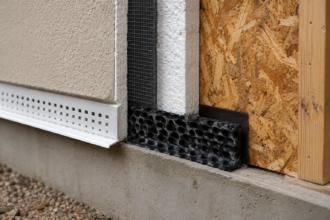
End dams are sheet metal closures at coping terminations: corners, transitions and roof-to-wall changes. Their function is to prevent lateral water migration from traveling along the underside of the coping pan and into the parapet assembly.
They are also the component most frequently underdetailed, undersized and incorrectly installed in the field. The end dam appears on fewer shop drawing details than any other coping component and when it does appear, the detail is often shown in elevation only, which conceals the depth dimension that governs performance.
The minimum end dam height that actually works is not a matter of opinion. The dam must extend from the top of the coping pan down to and beyond the outer face of the coping leg, with enough engagement to intercept water traveling along the cleat plane under wind pressure.
A dam that terminates flush with the bottom of the coping pan stops gravity-driven drainage. It does not stop wind-driven lateral migration, which is the dominant failure mode at parapet corners on buildings above three stories.
The pressure differential that drives wind-driven rain laterally along the cleat plane can exceed the hydrostatic head that gravity drainage calculations assume by an order of magnitude during sustained storm events. Designing the end dam for gravity drainage only is designing for the wrong load case.
The opening scenario on this article is not an outlier. It is a pattern.
The end dam at the parapet corner was fabricated to the coping pan depth and no further. Under sustained wind-driven rain, water entered the cleat plane at the lap joint, traveled laterally along the underside of the pan and exited behind the end dam into the parapet cavity.
Six months of that condition saturated the rigid insulation board and initiated corrosion on the steel deck below. The parapet cavity on that building was not ventilated, which meant the moisture that accumulated had no drying pathway.
The steel deck corrosion was active, not residual, when the destructive investigation was performed.
SMACNA’s 7th Edition details for end dam geometry show the correct configuration. The field fabrication on that project did not match those details.
The specification referenced SMACNA. The submittal showed a compliant detail.
The installed condition was neither. That three-step gap between specification, submittal and installation is not unusual.
It is the standard condition on projects where end dam geometry is not called out as a discrete inspection item during the pre-installation conference and verified by field observation during installation. An end dam that is 1/2 inch too short is not detectable after the coping is installed without removing the coping section.
By the time the building leaks and the investigation begins, the fabrication deficiency has been concealed by the completed installation for months or years.
The Specification-to-Field Gap That Makes All of This Worse
Specifications that reference SMACNA without requiring shop drawing review against project-specific wind uplift calculations create a false sense of compliance. SMACNA is a design reference, not a prescriptive standard with mandatory enforcement.
A contractor who installs 16-foot aluminum sections with fixed laps and undersized end dams has not violated a code section in most jurisdictions. The specification gap is real and it has consequences.
The International Building Code references SMACNA for sheet metal work in a general sense, but it does not mandate compliance with specific table values for coping section lengths or end dam heights. That means the enforcement mechanism is entirely contractual, which means it exists only if the specification creates it and the construction administration process verifies it.
The practical solution is not a longer specification. It is a mandatory pre-installation conference with the sheet metal subcontractor that addresses section lengths, slip joint locations, cleat gauge and spacing, end dam height and galvanic compatibility as discrete line items with project-specific values.
That conference, documented with sign-off from the installer, creates the chain of custody that forensic investigation and litigation both require. A pre-installation conference agenda that lists these items by name, with the project-specific design values entered next to each item, takes approximately 30 minutes to run and produces a document that is worth considerably more than its preparation time in any subsequent dispute about what was required and what was installed.
Shop drawing review must verify that stock lengths have been cut to comply with SMACNA section length limits, not simply that the submitted detail looks correct in elevation. An elevation drawing cannot show whether a 16-foot section was substituted for a 10-foot section in the field.
The shop drawing review comment that catches this substitution is specific: “Confirm that all coping sections as fabricated do not exceed [X] feet per SMACNA Table [X] for [aluminum/galvanized steel]. Provide a fabrication schedule showing cut lengths for all runs.
” That comment, added to the shop drawing review, creates a contractual record that the section length limit was communicated to the fabricator before installation began. Without it, the installer’s defense that the specification was ambiguous on this point has more traction than it deserves.
What the Next Failure Investigation Should Look Like
The investigator who arrives at a parapet coping failure with a probe, a moisture meter and a willingness to remove coping sections will find the actual failure mode. The investigator who arrives with a camera and a checklist focused on sealant condition will miss it.
Probe every end dam for height adequacy before touching the lap joints. A straightedge and a tape measure applied to the end dam at each coping termination takes less than two minutes per location and produces a measurement that either confirms or refutes compliance with the SMACNA detail.
Record the actual dimension, the SMACNA-required dimension and the delta. That comparison is the finding.
Manually test cleat engagement at the outer coping edge before evaluating sealant elongation. Check section lengths against SMACNA Chapter 4 limits before attributing anything to material degradation.
Measure actual installed gap widths at lap joints and compare them to the designed gap dimension from the approved shop drawing. Document whether the gap is compressed, within tolerance or overwide, because each condition points to a different failure mechanism.
The geometry fails first. The materials follow.
As extreme precipitation events increase in frequency across Mid-Atlantic and Gulf Coast exposure zones, the wind-driven rain loads that parapet copings must resist are exceeding the design assumptions embedded in standard SMACNA details. NOAA’s updated precipitation frequency data, reflected in the 2023 Atlas 14 revisions for several regions, shows design storm intensities increasing in the same exposure zones where parapet coping failures are already concentrated.
The industry’s answer cannot be better sealant. It has to be correct geometry, correct cleat attachment and end dam heights that actually intercept the water path that wind creates.
The buildings that fail next will fail for the same reasons the ones before them did. The geometry will be wrong and the sealant will look fine.