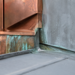
- Thin zinc sheet behaves fundamentally differently from aluminum composite material, and specifications that ignore that distinction produce predictable failures.
- Zinc manufacturers require substrate flatness of plus or minus 1.5 mm over 1.5 meters, a tolerance far tighter than standard steel stud framing delivers.
- Carbon steel and copper fasteners are electrochemically incompatible with zinc and will produce staining and section loss regardless of coating appearance.
- Fixed-point and sliding-point connection details must be explicitly designed for zinc’s thermal movement and cannot be borrowed from aluminum panel drawings.
- A pre-installation flatness survey with documented sign-off is the single contractual requirement most likely to prevent zinc cladding failures before they start.
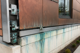
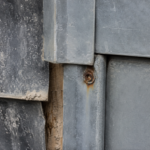
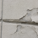
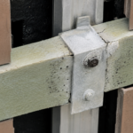
A facade engineer is called to a five-story mixed-use building in the Pacific Northwest three years after substantial completion. The thin zinc rainscreen panels are visibly oil-canned across two full elevations, several fastener heads have left rust-colored streaks down the patinated surface and two corner panels have begun to delaminate at their returns.
The contractor assumed zinc behaved like aluminum composite material. The spec sheet said nothing about substrate flatness tolerances.
The callback costs exceed the original cladding contract value.
This failure was not bad luck. It was a predictable outcome of specifying a material without understanding its dimensional sensitivity and electrochemical requirements.
Zinc Is New Here, Even If It Isn’t New
Zinc has clad European facades for over a century. In North America, it arrived in commercial rainscreen specifications relatively recently, driven by architect demand for pre-weathered and patinated metal aesthetics that painted aluminum cannot authentically replicate.
ASTM B69, the standard specification for rolled zinc, has existed since 1950. You would not know that from reading most U. S.
facade specifications, where the standard is rarely cited.
The material discussed here is rolled zinc alloy sheet, typically titanium-zinc, not zinc composite panels. Those are different products with different risk profiles.
Rolled zinc sheet carries the European installation tradition with it; the problem is that North American fabricators and installers largely do not share that tradition. The knowledge gap between a European zinc roofer with thirty years of experience and a domestic metal panel subcontractor who read the product data sheet last week is not a small gap.
It is where failures begin.
That gap has practical consequences at every project phase. During design, specifiers frequently copy zinc specifications from aluminum rainscreen sections, changing the product name but leaving the substrate, fastener and movement requirements unchanged.
During procurement, distributors may substitute fastener grades without flagging the change because the specification did not prohibit the substitution explicitly. During installation, crews accustomed to aluminum composite material handle thin zinc sheet with the same sequencing and torque settings they use on every other metal panel job.
None of those decisions feel wrong in the moment. The material goes on the wall, the project closes out and the problems develop over the next two to four thermal cycles.
By the time the facade engineer is on site, the original project team has moved on and the documentation trail is thin. Specifying zinc correctly means anticipating each of those handoff points and writing requirements that survive them.
Material Properties That Create Specification Risk
Zinc’s coefficient of thermal expansion runs approximately 22 x 10-6 per degree Celsius. Aluminum sits at roughly 23 x 10-6 per degree Celsius and steel at 12 x 10-6 per degree Celsius.
Zinc and aluminum move at nearly identical rates, which leads some specifiers to assume the two materials behave similarly in service. They do not.
Thin-gauge zinc, typically 0.7 mm to 1. 5 mm (20 to 16 gauge), has low yield strength and high ductility.
That combination makes it acutely sensitive to out-of-plane substrate irregularities in a way that aluminum sheet is not. When zinc bears unevenly across fastener points, thermal cycling induces stress concentrations that translate directly into visible oil-canning.
Unlike aluminum, zinc exhibits measurable creep at ambient temperatures. It does not spring back.
Zinc’s electrochemical position compounds the risk. Zinc sits anodic to steel and copper in the galvanic series.
Place a carbon steel fastener against zinc in the presence of moisture and you have constructed a corrosion cell. The outcome is not uncertain; it is a matter of time and exposure.
ASTM B69-16 governs alloy compositions and thickness tolerances for rolled zinc in North American specifications. European manufacturer data sheets frequently reference EN 988 instead.
When a specifier pulls a manufacturer’s technical manual and the referenced standard is EN 988, they need to resolve that standards-alignment gap explicitly in the specification. Most do not.
The yield strength difference between zinc and aluminum deserves a specific number. Mill-finish aluminum sheet at 0.080 inches carries a yield strength in the range of 16,000 to 35,000 psi depending on alloy and temper.
Titanium-zinc sheet at comparable thickness yields at roughly 14,500 to 18,000 psi, but its elongation at break runs 30 to 40 percent, far higher than most aluminum alloys used in cladding applications. That high elongation is what allows zinc to deform plastically under uneven bearing rather than cracking.
The deformation is permanent. A panel that oil-cans under the first summer’s thermal load will not recover when temperatures drop.
Specifiers who have worked only with aluminum composite material or aluminum sheet systems have no field reference for that behavior and frequently misread early oil-canning as an installation defect that will self-correct. It will not.
Substrate Flatness: The Tolerance Nobody Writes Down
This is where the majority of zinc cladding failures originate. Steel stud framing with sheathing typically carries a flatness tolerance of plus or minus 3 mm over 3 meters, consistent with ASTM C1007-11 for load-bearing steel stud installation.
Zinc manufacturers require substrate flatness of plus or minus 1.5 mm over 1. 5 meters.
That is a fundamentally different tolerance and it is rarely written into construction documents or verified at any inspection milestone.
The mechanism is straightforward. When panel bearing points are not coplanar, thin zinc deflects between fasteners under thermal cycling.
The characteristic waviness of oil-canning develops because the panel cannot distribute load evenly across its face. Aluminum composite panels tolerate this better because their sandwich construction provides stiffness that thin zinc sheet simply lacks.
Zinc’s creep behavior means the deformation accumulates over time rather than recovering between thermal cycles. By year three, what started as marginal substrate flatness becomes visible distortion across an entire elevation.
The responsibility gap makes this worse. On a typical mid-rise commercial project, the framing contractor, sheathing installer, girt or hat-channel installer and zinc panel installer are four separate trades.
No single party owns cumulative flatness tolerance across that sequence. Each trade meets its own scope requirement and hands off to the next.
The specification must break this pattern by establishing a pre-installation flatness survey milestone with documented sign-off before zinc panel installation begins. Without that contractual requirement, no one will measure anything.
Substrate options vary in their flatness achievability. Steel hat channel installed over continuous sheathing gives the most control because hat channel can be shimmed and adjusted before fastening.
Thermally broken aluminum extrusion systems offer good flatness control but require verification of zinc-to-aluminum contact compatibility at bearing points. Direct-to-stud attachment carries the highest risk and the least flatness control; for thin zinc sheet, it should be treated as a non-starter unless the stud layout is extraordinarily tight and independently surveyed.
The specification should identify the substrate system and state the flatness requirement explicitly, with the tolerance referenced to the zinc manufacturer’s published installation manual.
The flatness survey itself requires a defined method to be enforceable. A straightedge and feeler gauge check at isolated points is not sufficient for a full elevation.
The specification should require a grid-based survey using a laser level or digital level, with measurement points at every fastener location or at maximum 300 mm intervals across the panel field, whichever is tighter. Results should be recorded on a dimensioned elevation drawing and submitted to the architect of record before panel installation begins.
If the survey reveals out-of-tolerance conditions, the specification should require a remediation plan from the framing or girt installer before zinc work proceeds. That remediation plan requirement is what gives the zinc installer contractual standing to stop work rather than proceeding over a substrate they know is wrong.
Without it, schedule pressure wins every time.
Fastener Material Compatibility: What the Spec Must Prohibit
Carbon steel fasteners corrode against zinc. This is not a conditional statement.
When the zinc electroplating on a standard zinc-coated screw is breached, which happens at the point of installation when the fastener is driven, the exposed steel substrate becomes anodic relative to the surrounding zinc panel in the presence of moisture. The result is iron oxide staining that runs down the patinated zinc face and progressive fastener section loss that compromises panel retention over time.
Acceptable fastener materials for direct zinc contact are 304 or 316 stainless steel, hot-dip galvanized steel meeting ASTM A153-16 Class C or D coating weight minimums or manufacturer-approved aluminum alloy fasteners where panel geometry permits. Copper and brass fasteners are categorically prohibited.
Copper sits cathodic to zinc in the galvanic series; contact in a wet condition accelerates zinc corrosion at a rate that will produce visible surface degradation within a few years in IECC Climate Zones 4 through 6 where Pacific Northwest projects typically fall.
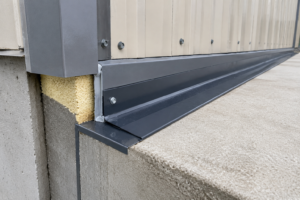
Fixed-point connections require EPDM or neoprene isolation washers regardless of fastener material. The washer serves two functions: it prevents fretting corrosion at the fastener-to-panel interface under thermal movement and it accommodates the differential movement between the panel and the substrate structure.
Specify washer durometer and UV resistance requirements. A washer that degrades in five years of UV exposure provides no long-term protection.
The procurement risk here is real and specific. Zinc-electroplated screws and hot-dip galvanized screws are visually indistinguishable on the job site.
A fastener substitution made at the point of purchase, not even at installation, can undermine the entire corrosion protection strategy without anyone noticing until the staining starts. Require mill certifications and lot-specific fastener submittals.
Include a field verification protocol in the specification that gives the inspector a basis for rejection if certifications cannot be produced.
The 316 stainless steel designation matters more than the 304 designation in coastal and high-humidity exposures. Both alloys are austenitic and non-magnetic in their annealed state, which means field identification by magnet is unreliable.
The molybdenum content in 316, typically 2 to 3 percent by weight, provides measurably better resistance to chloride pitting than 304. In Climate Zone 4C marine exposures, which covers much of the Pacific Northwest coast, specifying 304 as the minimum acceptable grade and accepting 316 as a substitution is backwards. The specification should require 316 as the minimum in marine-adjacent exposures and permit 304 only at interior or sheltered locations where the inspector can verify the reduced exposure condition.
That distinction is rarely made in specifications and almost never enforced in the field, but it is the difference between a fastener that performs for thirty years and one that begins to show crevice corrosion at the washer interface within a decade.
Fixed Points, Sliding Points and Movement Accommodation
Zinc moves. Every panel attachment detail must account for it.
The standard approach uses a fixed point at one location per panel, typically centered and sliding connections at all remaining fastener locations. Sliding connections use slotted holes in the panel clip or bracket to allow thermal expansion and contraction without restraining the panel face.
The fixed-point location matters. Centering the fixed point allows equal movement in both directions and minimizes the stress differential across the panel face.
An off-center fixed point creates asymmetric restraint; under repeated thermal cycling, the panel will telegraph that asymmetry as distortion. This detail is rarely shown explicitly on architectural drawings and is frequently left to the installer’s judgment.
That is a specification failure, not an installer failure.
Slot orientation must align with the primary direction of thermal movement. For horizontal panels, slots run horizontally.
For vertical panels, slots run vertically. Diagonal slots or round holes at sliding connections defeat the purpose entirely.
The specification should require shop drawing submittals that show fixed-point locations and slot orientations for each panel type and confirm that the movement accommodation calculation has been performed for the project’s design temperature range.
The movement calculation is not complicated, but it must be performed with the correct inputs. The design temperature range for a Pacific Northwest project might run from minus 5 degrees Celsius to plus 50 degrees Celsius at the panel surface, accounting for solar gain on a south or west elevation.
A 900 mm wide zinc panel across that 55-degree range expands approximately 1.1 mm. The slot length must accommodate that movement plus a construction tolerance allowance, typically an additional 1.5 mm minimum, for a total slot length of at least 2.
6 mm beyond the fastener shank diameter. Specifiers who copy slot dimensions from a previous aluminum project without recalculating for zinc’s expansion coefficient and the project-specific temperature range are not making a large numerical error, but they are eliminating the tolerance buffer that protects the panel when installation alignment is imperfect.
The shop drawing review is the last opportunity to catch that error before the panels go on the wall.
Sealant and Joint Design at Panel Edges
Open-joint rainscreen assemblies are common with zinc sheet and for good reason: they eliminate the sealant maintenance liability and allow the cavity to drain and dry effectively. But open joints require a continuous air barrier behind the panel that is detailed to manage both water and air control at the assembly level.
Zinc rainscreen panels are a cladding layer, not a water control layer. The water control function belongs to the WRB or air barrier membrane behind the cavity.
Closed-joint assemblies with sealant at panel edges introduce a different risk. Standard silicone sealants bond poorly to patinated or pre-weathered zinc without proper surface preparation and primer.
A sealant joint that fails adhesively on a zinc panel face will admit water directly to the fastener zone. Specify sealant compatibility testing per ASTM C719 for movement accommodation and require adhesion testing per ASTM C794 against the actual zinc surface finish, not a generic metal substrate.
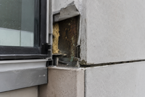
Corner returns and edge conditions concentrate stress. The delamination at corner returns in the failure scenario above is a direct consequence of inadequate return depth combined with a fixed-point connection that restrained thermal movement at the most vulnerable geometry in the panel.
Return depths for thin zinc sheet should follow manufacturer minimums and the fixed-point detail at corners requires explicit design attention, not a field decision.
The air barrier continuity requirement at open-joint assemblies deserves more specification attention than it typically receives. A self-adhered membrane or fluid-applied air barrier behind a zinc rainscreen must be detailed to maintain continuity at every penetration, transition and termination condition.
That includes girt attachments, window head and sill conditions, through-wall scuppers and any structural element that interrupts the plane of the air barrier. AAMA 508-07, the voluntary specification for pressure-equalized rainscreen wall cladding, provides a framework for cavity pressure equalization that applies directly to open-joint zinc assemblies.
When the air barrier is discontinuous, the cavity does not pressure-equalize properly and water entry at open joints increases. The zinc panels take the visual blame, but the failure mechanism is behind them.
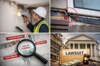
Specifying the zinc panel system without specifying the air barrier system it depends on is an incomplete scope of work and it is a gap that shows up regularly in forensic investigations of rainscreen failures.
Write the Specification Before You Approve the Submittal
Zinc cladding failures in North America follow a consistent pattern: the material is specified by reference to a manufacturer’s product data sheet, the substrate and fastener requirements buried in the installation manual never make it into the project specification and the installer treats zinc like aluminum composite material because nothing in the contract documents tells them otherwise.
The specification must state the substrate flatness requirement by number, reference ASTM B69-16 for material compliance, prohibit carbon steel and copper fasteners by name, require lot-specific fastener certifications and establish a pre-installation flatness survey as a contractual milestone. If those requirements are not in the specification before the submittal review begins, the submittal process will not catch the gap.
By the time the panels are on the wall, the opportunity to prevent the failure has passed.
The submittal review sequence matters as much as the specification content. The flatness survey submittal should be a required predecessor to the panel installation submittal in the project schedule.
Shop drawings showing fixed-point locations, slot orientations and movement calculations should be reviewed and approved before any panel fabrication begins, not concurrently with installation. Fastener certifications should be received and logged before the fasteners arrive on site, not after the first panels are hung.
Each of those sequencing requirements can be written into Division 01 submittal procedures or into the zinc panel section itself. If they are not written somewhere, the default project schedule will compress all of those reviews into the two weeks before installation starts, which is not enough time to identify and correct a fastener specification error or a substrate flatness deficiency.
The five-story building in the Pacific Northwest did not fail because zinc is a difficult material. It failed because the specification did not define what success looked like before the work began.