

- Polyisocyanurate boards can lose up to 38% of their labeled R-value at mean temperatures below 25°F.
- ASHRAE 90.1-2022 permits compliance calculations using labeled values that do not reflect cold-climate field performance.
- Foil-faced polyiso creates double-vapor-retarder risks that increase condensation potential at the sheathing plane.
- Bracket creep and missing pull-through calculations leave cladding attachment systems structurally and thermally compromised.
- Specifiers should use derated R-values of R-4.0 to R-4.5 per inch for Climate Zone 6 and 7 compliance calculations.
Polyiso CI at Metal Stud Walls: The Cold-Climate R-Value Gap
A polyisocyanurate board labeled R-6.5 per inch can deliver as little as R-4. 0 per inch at mean temperatures below 20°F: a 38% reduction that no permit reviewer checks and no energy model flags automatically.
For facade engineers specifying 3-inch polyiso to hit ASHRAE 90.1-2022 continuous insulation requirements in Climate Zone 6, that gap is the difference between a compliant assembly and one that underperforms by more than a full R-10. The labeled value is a laboratory artifact.
The installed value is a cold-climate liability.
Why Polyiso Became the Default CI Board for Metal Stud Facades
Polyisocyanurate captured the commercial CI market for a straightforward reason: it offers the highest labeled R-value per inch of any board insulation in common use, ranging from R-5.7 to R-6. 5 depending on facer type and board density.
That density advantage matters enormously at the wall. Every additional inch of CI thickness compresses rough opening dimensions, complicates fenestration installation details and drives up cladding attachment bracket lengths.
A thinner board that still clears the code threshold is a specification win on paper.
Cold-formed steel stud backup walls made polyiso even more attractive. The boards are lightweight, field-cuttable and available in tapered profiles that support positive drainage plane geometry without shimming.
They tolerate the tolerances of CFS framing better than rigid mineral wool in many installation sequences. On projects with 16-inch stud spacing and 3.5-inch deep framing, the ability to cut and fit polyiso around clip angles and blocking without cracking or crumbling is a real field advantage that mineral wool boards at equivalent thickness cannot always match.
The cost-per-R calculation historically sealed the decision. Without a lifecycle thermal adjustment for cold-climate performance depression, polyiso consistently undercut EPS and XPS on a dollars-per-R basis at the labeled value.
Specifiers running that calculation were not being careless. They were using the numbers the industry provided.
A project with 80,000 square feet of exterior wall area and a 1-inch thickness reduction in CI translates directly into reduced bracket lengths, narrower window bucks and lower installed cost across every trade touching the facade. The economic pressure to specify the thinnest compliant board is real and compounds across project phases.
ASHRAE 90.1-2022 Table 5. 5-5 accelerated adoption further.
Prescriptive CI minimums for metal-framed above-grade walls in Climate Zones 5 through 7 pushed specifiers toward the highest labeled R-value product available, because thicker assemblies create compounding problems at every penetration, transition and fenestration rough opening. A Climate Zone 7 project requiring R-16.8 of CI on a metal-framed wall can meet that threshold with approximately 2.
6 inches of polyiso at labeled values. The same requirement in mineral wool demands nearly 4 inches of product at R-4.2 per inch, adding bracket length, dead load and cost at every cladding attachment point.
Polyiso looked like the answer. In cold climates, it frequently is not.
The Cold-Temperature R-Value Depression Problem: What the Data Actually Show
The mechanism is physical, not a manufacturing defect. Polyisocyanurate foam uses closed-cell structure with blowing agents that remain in gaseous form at moderate temperatures, contributing meaningfully to thermal resistance.
Below roughly 40°F mean temperature, those blowing agents begin to condense. When they condense, the gas-phase contribution to R-value collapses.
The foam cells are still intact. The thermal resistance simply is not.
Oak Ridge National Laboratory research on polyiso temperature dependence documented this behavior systematically. Tested boards returned R-values in the range of R-3.8 to R-4.
2 per inch at a mean temperature of 25°F, depending on facer type and board density. Foil-faced boards tend to perform slightly better than felt-faced at low temperatures, but neither category approaches the labeled value under cold-climate conditions.
This is not an outlier finding. It has been replicated across multiple testing programs commissioned by NRCA and PIMA.
The ORNL data also showed that performance depression is not a step function. R-value begins declining measurably below 50°F mean temperature and continues declining as mean temperature drops, meaning the effective R-value of a CI board in a Minneapolis wall assembly shifts throughout the heating season rather than holding at a single depressed value.
ASTM C518 governs the steady-state heat flux measurement used to generate labeled R-values. The standard test is conducted at a mean temperature of 75°F.
That temperature is appropriate for laboratory reproducibility. It is not representative of a CI board installed on the exterior of a metal stud wall in Minneapolis in January, where mean temperatures across the board thickness routinely fall below 25°F for extended periods.
The cold plate in a C518 test apparatus runs at 50°F and the hot plate at 100°F, producing a 75°F mean. In a Climate Zone 6 wall during a design-day event, the exterior surface of the CI board may sit at minus 10°F while the interior face approaches 40°F, producing a mean temperature across the board of roughly 15°F.
The C518 test condition and the field condition share almost nothing in common.
ASTM C1289 classifies polyisocyanurate boards by facer type and establishes minimum R-value requirements for labeled performance. It does not require manufacturers to publish temperature-dependent performance curves.
Some manufacturers reference CAN/ULC-S770 Long-Term Thermal Resistance protocols, which address aging effects but not temperature depression. The LTTR value is a 15-year aged estimate at standard test temperature.
It is not a cold-climate performance value. Specifiers who read LTTR data as a conservative real-world number are compounding two separate errors: aging correction does not substitute for temperature correction and the two adjustments are not additive in any straightforward way.
The structural gap is this: ASHRAE 90.1-2022 and most state energy codes that reference it permit compliance calculations using manufacturer labeled R-values. A specifier can document full compliance with the prescriptive path using numbers that diverge by 38% from what the assembly actually delivers at design conditions.
No commissioning protocol catches this. No blower door test reveals it.
The building simply loses more heat than the energy model predicted.
How ASHRAE 90.1-2022 CI Requirements Interact With Labeled vs. In-Situ R-Values
ASHRAE 90.1-2022 Table 5. 5-5 sets the prescriptive CI minimum for metal-framed above-grade walls in Climate Zone 6 at R-11.7. A specifier using 2-inch polyiso at a labeled R-6.
5 per inch calculates R-13.0 and documents a compliant margin of 1. 3 R.
That margin feels conservative. It is not.
At in-situ cold-climate performance of R-4.0 per inch, that same 2-inch board delivers an effective R-value of R-8. 0 across the CI layer alone.
The compliance deficit is R-3.7. Specifying 3-inch polyiso at labeled R-6. 5 per inch produces R-19.5 on paper and roughly R-12.
0 at cold-climate in-situ conditions, which still clears the R-11.7 threshold but eliminates every margin that the specifier believed they had built in. A project team that specified 3-inch polyiso expecting a 7.8 R margin above the prescriptive minimum is actually operating at a 0.
3 R margin, with no buffer for attachment hardware thermal bridging, board joint gaps or transition details that inevitably underperform the field condition.
The whole-wall calculation compounds this. Thermal bridging through cold-formed steel framing already reduces the effective R-value of the cavity insulation layer by 50% or more at typical stud spacings.
ASHRAE 90.1 Appendix A provides correction factors for metal-framed assemblies that account for this bridging and those factors are not gentle. A wall framed with 6-inch 20-gauge studs at 16 inches on center with R-19 batt insulation in the cavity returns an effective cavity R-value of approximately R-7.5 after framing correction.
CI is supposed to address that bridging. But CI attachment brackets, shelf angles and penetrations introduce their own point and linear thermal bridges.
The effective R-value of the complete assembly is always lower than the sum of its nominal components and polyiso depression stacks directly on top of that reduction.
ASHRAE 90.1-2022 Section 3 defines continuous insulation strictly in terms of installation continuity: insulation that is continuous across all structural members without thermal bridges other than fasteners and service openings. The definition addresses geometry.
It does not address temperature-dependent material performance. Section 5.6 provides trade-off and performance path options, but those paths still permit labeled R-values as inputs.
An energy model fed labeled polyiso values will produce a compliant result that does not reflect actual thermal performance in Climate Zone 6 or 7 winter conditions. Energy modelers using EnergyPlus or eQUEST who input the labeled R-value without a temperature correction are not making a modeling error by the rules of the code.
They are making a physical error that the code does not yet require them to correct.
Vapor Permeability Mismatch at the Sheathing Interface: The Overlooked Hygrothermal Risk
Polyiso facer selection drives vapor control behavior and most specifications treat it as an aesthetic or availability decision. That is a mistake.
Foil-faced polyiso is a Class I vapor retarder at 0.1 perm or less. Felt-faced polyiso, depending on facer composition and board thickness, ranges from Class II to Class III.
Those are not interchangeable vapor control layers and substituting one for the other mid-project because of a supply chain delay can fundamentally alter the hygrothermal behavior of the assembly without triggering any formal design review.
In a typical CFS backup wall assembly for Climate Zone 6 or 7, the layer sequence runs from interior to exterior: gypsum board, interior vapor retarder (where specified), CFS framing with batt insulation, gypsum sheathing, air barrier membrane, polyiso CI and cladding. Place foil-faced polyiso outboard of the gypsum sheathing with an interior vapor retarder also in the assembly and you have created a double-vapor-retarder condition.
Moisture that migrates into the sheathing layer from either direction has nowhere to go. Gypsum sheathing is not a moisture-tolerant substrate.
Glass mat gypsum products like DensGlass or similar perform better than paper-faced alternatives, but neither product is designed to sustain repeated wetting and drying cycles at the sheathing plane without degradation of the mat facing and eventual loss of fastener pull-through capacity.
The dew point analysis is not optional in CZ6 and CZ7. During winter design conditions, the sheathing interface temperature will fall below the interior dew point for extended periods. Without sufficient outboard R-value to keep that interface above the dew point, condensation risk at the gypsum sheathing plane is real and documented.
The depressed effective R-value of polyiso at cold temperatures makes this worse: the specifier calculated a sheathing temperature that assumed R-13.0 of outboard insulation and got R-8. 0 instead.
That 5 R-value difference translates to a sheathing plane temperature that is measurably colder than the design assumed, shifting the condensation risk window from a few weeks per year to potentially several months. Field investigations on CZ6 commercial projects have documented mold growth and mat delamination at the sheathing plane within three to five years of occupancy in assemblies that appeared compliant on paper.
Felt-faced polyiso improves drying potential to the exterior, which matters when the sheathing plane gets wet. It sacrifices some nominal thermal performance relative to foil-faced and performs similarly under cold-temperature depression.
The specifier decision is not which facer looks better. It is which vapor control strategy the assembly can actually sustain across all four control layers: water, air, vapor and thermal.
ASHRAE 160-2016 provides the design criteria for that analysis. Running it with depressed polyiso R-values rather than labeled values changes the outcome materially in cold climates.
A hygrothermal simulation using WUFI or similar tools that inputs R-13.0 of outboard CI will predict a sheathing plane moisture content that differs significantly from the same simulation run at R-8. 0.
The difference is not academic. It determines whether the assembly is durable or whether it is accumulating a moisture problem that will not become visible until the warranty period has expired.
Fastener Pull-Through and Attachment Limits at the CI Layer
The structural attachment of CI boards to CFS backup walls is where specification intent and field reality diverge most sharply. Polyiso boards are not structural substrates.
Their compressive strength and pull-through resistance at the fastener point are limited and those limits govern how the cladding load path actually works.
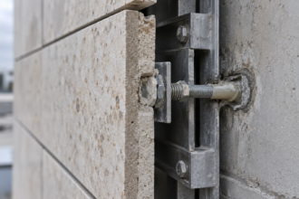
Cladding attachment brackets that bear against the face of polyiso CI compress the foam under sustained load. The compression is not elastic recovery.
It is creep and it continues over time. A bracket torqued to specification on day one will have a different bearing condition in year three.
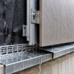
The effective thermal bridge created by that bracket also changes as the air gap geometry shifts. Bracket systems designed with a fixed standoff dimension to maintain a specific air gap behind the cladding can lose that gap geometry as the foam creeps under the bearing plate, bringing the cladding closer to the CI surface and altering both the drainage plane geometry and the thermal performance of the ventilated cavity.
This is not a theoretical concern. Facade forensic investigations on rainscreen assemblies installed over polyiso CI have documented bracket bearing plate settlement of 3 to 6 millimeters over five-year periods, which is enough to close a nominally 10-millimeter drainage gap by a meaningful fraction.
Long screws through CI boards into CFS framing carry both the CI board and, in some systems, the cladding load. Pull-through capacity at the polyiso facer is a function of facer type, board density and screw diameter.
Foil-faced boards generally provide better pull-through resistance than felt-faced at equivalent density. Neither facer type substitutes for proper engineering of the attachment pattern and most specifications do not include pull-through calculations for the CI layer itself.
The gap in standard practice is that Division 07 specifications routinely call out CI board product type and thickness without requiring the contractor to submit pull-through load data or verify that the proposed fastener pattern meets the project wind uplift requirements. That verification step falls between the CI board spec and the cladding attachment spec and it frequently falls through entirely.
The practical consequence is that attachment spacing and fastener selection for polyiso CI must account for wind uplift, cladding dead load, seismic load path requirements and the creep behavior of the foam under sustained compression. ASTM E1300 governs glass load, not CI attachment; the applicable test protocols for CI board attachment under combined loading are not universally standardized, which means the specifier needs to demand manufacturer-specific load data and verify it against the project’s wind exposure category and cladding weight.
ICC-ES evaluation reports for specific CI board products sometimes include pull-through and compressive creep data, but those reports are product-specific and not always current. Requiring the CI board manufacturer to provide a letter of compliance with the project’s specific loading conditions, signed by a licensed engineer, is a reasonable specification requirement that most projects do not currently include.
Detailing at Transitions: Where the Thermal and Moisture Control Layers Actually Fail
Polyiso CI performs as designed only when the board joints are tight, the penetrations are sealed and the terminations at shelf angles, parapets and fenestration rough openings maintain continuity across all four control layers. In practice, those conditions are rarely met without explicit detailing and inspection.
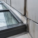
Shelf angles interrupt CI continuity at every floor line. The standard approach of cutting the CI board around the shelf angle and patching with cut pieces leaves thermal bridges and air leakage pathways that accumulate across a multi-story facade.
The effective R-value at those interruptions is not zero, but it is significantly lower than the field and the air barrier continuity at those transitions is only as good as the membrane detailing that bridges the gap. On a 10-story building with shelf angles at every floor, that interruption repeats 9 times across the facade height.
Each interruption represents a linear thermal bridge that, when calculated using ISO 10211 methods, can reduce the whole-wall effective R-value by an additional 5 to 10 percent depending on shelf angle size, projection and the quality of the CI patching around it. Specifiers who calculate compliance at the field condition and assume the transition details are adequate are not accounting for the thermal penalty that accumulates at those floor lines.
Fenestration rough openings in CI assemblies require the window or door unit to be set within the CI plane or the CI to wrap the opening. Neither approach is simple with polyiso.
The boards are cuttable but not flexible and the inside corner at a rough opening is a documented failure point for both air barrier membrane continuity and thermal bridging. A 3-inch polyiso assembly at a rough opening corner, with a bracket or substrate transition, can deliver an effective R-value well below R-5 at that location regardless of what the field delivers elsewhere.
The air barrier membrane must make a continuous transition from the wall plane into the rough opening return and connect to the window frame or sill flashing without bridging across the CI layer. That transition requires a membrane product with sufficient elongation to accommodate substrate movement, a compatible primer on the polyiso facer and a mechanical termination at the window frame that will not pull free under thermal cycling.
Most project specifications describe the air barrier product and its application in the field but do not include a drawn detail for the rough opening corner condition. The installer interprets the intent in the field and field interpretations at inside corners are frequently inadequate.
These are not unusual conditions. They are the standard geometry of every commercial facade project.
The details need to be drawn, specified and verified in the field. Relying on the nominal R-value of the field condition to compensate for transition failures is not a strategy.
Specifying Polyiso in Cold Climates Without Getting It Wrong
The answer is not to stop specifying polyiso. It remains a legitimate CI material with real advantages in weight, thickness and cost.
The answer is to specify it honestly, with performance values that reflect actual cold-climate conditions rather than laboratory artifacts.
Start the energy compliance calculation using a derated R-value. For Climate Zone 6 and 7 projects, apply an in-situ R-value of R-4.0 to R-4.
5 per inch for the compliance calculation rather than the labeled value. If the prescriptive path fails at that derated value, either increase thickness, switch to a material without temperature-dependent depression (mineral wool CI does not exhibit this behavior) or document the trade-off through the performance path with honest inputs.
Some jurisdictions are beginning to require temperature-corrected R-values for polyiso in cold climates; check local amendments before assuming labeled values are acceptable. Minnesota’s energy code amendments and the Massachusetts Stretch Code have both moved toward requiring more conservative polyiso R-value inputs in cold-climate compliance calculations and other states in Climate Zones 6 and 7 are tracking those precedents.
Specify facer type based on vapor control strategy, not availability. Run the ASHRAE 160-2016 dew point analysis with derated polyiso R-values before selecting foil-faced or felt-faced product.
Require pull-through load data from the CI board manufacturer and verify it against the cladding attachment design. Detail every shelf angle interruption, every fenestration rough opening transition and every penetration through the CI layer as a distinct drawing.
Require the air barrier membrane manufacturer to review and approve the rough opening corner detail before installation begins. Include a special inspection requirement in the project specifications for CI board joint taping, fastener pattern verification and air barrier membrane terminations at all transitions.
The assembly performs as its worst detail, not its best field condition.
Polyiso’s cold-climate R-value depression has been documented for more than a decade. Specifying around it is not a research project.
It is due diligence.