Copper and Zinc Composite Cladding Panels: Galvanic Compatibility, Substrate Restrictions and Where the Aesthetic-First Specification Creates Structural Risk
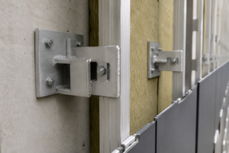
A hospitality project in the Pacific Northwest specified copper composite panels across a six-story rainscreen facade. Eighteen months after occupancy, white streaking appeared on the limestone base course and the aluminum sub-girt connections showed active corrosion at every panel clip location.
The project team had followed the ACM installer’s standard detail set without modification. The copper composite manufacturer’s technical bulletin, which explicitly prohibited direct aluminum contact and required isolating tape at all substrate connections, had never been distributed to the facade subcontractor.
The architect had selected the material for its patina potential. Nobody had read the installation requirements before the shop drawings were approved.
That failure is not unusual. It is increasingly common.
What Copper Composite Panels Actually Are: And What They Are Not
Copper composite panels consist of a thin copper face sheet, typically 0.012″ to 0. 020″ thickness per ASTM B370 alloy classifications, bonded to either a polyethylene core or a fire-rated mineral core, with an aluminum or steel backer sheet completing the sandwich.
C11000 electrolytic tough pitch copper is the most common face sheet alloy in commercial composite products. The panel format is physically identical to standard aluminum composite material, which is precisely where the specification risk begins.
These are not solid copper cladding panels. They are not copper-coated aluminum panels.
The distinction matters because the compatibility and substrate requirements are driven entirely by the copper face, not by the core material or the backer sheet. Project teams that understand the core as “basically ACM with a copper skin” have already made the error that produces the failure described above.
The physical similarity to ACM extends to panel dimensions, edge profiles and routing geometry, which means fabricators working from shop drawings can process copper composite panels on the same equipment and with the same toolpaths used for aluminum composite. That operational similarity reinforces the false assumption that the installation requirements are also identical.
They are not. The copper face sheet changes every downstream compatibility decision, from sub-girt material selection to fastener specification to joint sizing to adjacent material planning.
A project team that treats the copper face as a cosmetic upgrade to a standard ACM assembly will encounter substrate failures that the ACM detail set was never designed to prevent.
C11000 copper in thin sheet form is also more susceptible to surface damage during fabrication and handling than aluminum face sheets. Scratches that would be acceptable on an aluminum panel expose bare copper at the scratch location, which weathers differently than the surrounding patinated surface and produces visible streaking patterns that are not the aesthetic the specification intended.
Handling protocols for copper composite panels during fabrication, transport and installation require specific attention that standard ACM handling procedures do not address. Specifiers who include copper composite in a project without addressing handling requirements in the contract documents are transferring that risk entirely to the subcontractor, who will manage it using ACM protocols that are not adequate.
Zinc composite panels, including those using RHEINZINK and VM Zinc alloy sheet faces, present similar galvanic concerns but with different reactivity profiles. Zinc sits lower in the electrochemical series than copper, which changes the corrosion hierarchy at connection points.
The two product categories are not interchangeable in terms of substrate compatibility requirements and a specification that addresses one does not automatically address the other.
Most project teams default to ACM installation details because the panel format is identical. That false equivalency enters the project at the first shop drawing submittal and rarely gets corrected before steel is in the ground.
The Galvanic Corrosion Problem at Aluminum Sub-Girt Connections
Copper sits at approximately +0.34V and aluminum at approximately -0. 76V in the standard electrochemical series.
That 1.1V potential difference is not a marginal concern. It is one of the most aggressive dissimilar metal pairings in common building construction and it becomes an active corrosion cell the moment moisture bridges the contact point between a copper panel clip and an aluminum sub-girt.
The failure pathway in a rainscreen assembly is specific and predictable. Condensation and wind-driven moisture accumulate at the panel clip.
If isolating tape is present but a fastener has penetrated through it, which happens routinely when installers are working from ACM details that don’t call out non-conductive washers, capillary wicking carries the electrolyte along the sub-girt flange. The aluminum corrodes preferentially as the anode.
This is not cosmetic surface oxidation. It is anodic dissolution that degrades the structural section of the sub-girt over time, concentrated at the highest-stress locations: the clip connections.
The rate of anodic dissolution accelerates with increasing electrolyte conductivity. In coastal environments, where airborne chloride concentrations are elevated, the corrosion rate at an unprotected copper-aluminum contact point can be three to five times higher than in a dry inland climate.
A sub-girt failure that might take eight to ten years to reach structural significance in a low-humidity interior climate can reach the same degradation threshold in three to four years on a coastal facade. Specifiers working on projects within one mile of saltwater should treat the isolation requirements as an absolute minimum and consider specifying stainless steel sub-girts as the primary framing material rather than relying on isolation tape to protect aluminum framing from a corrosion mechanism that is significantly more aggressive in that environment.
Stainless steel fasteners through aluminum sub-girts in contact with copper panels create a three-metal galvanic cell. Stainless 316 is acceptable for fastener specification provided the copper-to-aluminum contact is fully isolated by other means.
The fastener material is not the primary isolation strategy. It is a secondary consideration.
Isolation requirements across major copper composite product lines are consistent: EPDM or neoprene isolating tape at minimum 1/16″ thickness at all contact points, non-conductive washers at fastener penetrations and full dielectric separation of the copper face from aluminum framing. ASTM G71 provides the test methodology basis for manufacturer compatibility data and the threshold values from that standard are what drive the 1/16″ minimum separation requirement cited in technical bulletins from multiple product manufacturers.
This is not a conservative best practice recommendation. It is a minimum.
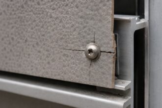
Field observation across multiple copper composite projects confirms that the most common isolation failure is not absent tape but compressed tape. EPDM isolating tape at 1/16″ uncompressed thickness loses a significant portion of its dielectric separation when a fastener is overtorqued through the connection.
Installers working from ACM details have no torque specification for clip fasteners because aluminum-to-aluminum contact does not require one. Copper composite installation details must include explicit fastener torque limits at clip connections to prevent tape compression that defeats the isolation.
That requirement is absent from every ACM detail set and must be added by the specifier or facade consultant before the detail set reaches the subcontractor.
Specifiers who carry ACM sub-girt details into copper composite projects without modification are not making a judgment call. They are ignoring explicit manufacturer requirements.
Runoff Staining: Scope, Permanence and Adjacent Material Restrictions
Copper patination is the aesthetic that drives the specification. It is also the mechanism that destroys adjacent materials.
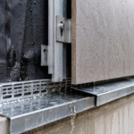
Copper oxide and copper carbonate compounds, the primary patina constituents, are water-soluble in the early weathering stages before the patina stabilizes. Those compounds migrate downward with every rain event and they permanently stain porous materials on contact.
Limestone, concrete, brick, EIFS and light-colored fiber cement panels are all high-risk adjacencies. The staining is not surface contamination that pressure washing removes.
The copper compounds penetrate the pore structure of the substrate. On limestone, the reaction produces a blue-green stain that is chemically bonded to the calcium carbonate matrix.
Restoration is not a realistic option on a facade scale.
The weathering timeline matters for understanding when staining risk is highest. Freshly installed copper composite panels with a mill finish or a pre-weathered factory patina will begin producing soluble copper compounds within the first rain events after installation.
The soluble compound production rate is highest in the first 18 to 36 months of exposure, before the patina layer stabilizes into the relatively insoluble copper carbonate and copper sulfate compounds that characterize mature patina. That early weathering period is when the most aggressive staining of adjacent materials occurs and it coincides exactly with the period when the building owner is most likely to be evaluating the facade for warranty claims and aesthetic performance.
Projects that install copper composite panels adjacent to limestone base courses or precast concrete spandrels without runoff mitigation will generate staining claims before the first lease renewal cycle.
The Copper Development Association’s Publication A4050 addresses copper runoff effects on adjacent building materials and recommends minimum 18″ to 24″ horizontal setback from copper panel terminations to porous adjacent materials. Vertical runoff paths extend the full height of the facade below any copper element.
On a six-story building, every porous material at grade level is at risk from copper runoff originating at the second floor.
The highest-risk adjacencies on institutional and hospitality projects are exactly the materials those project types favor: cast stone sills, precast concrete spandrels, light-colored fiber cement panels and white or buff brick. Design mitigation options include stainless steel or copper drip edges at panel terminations, concealed gutters at floor lines and hydrophobic sealant treatment of adjacent masonry.
Hydrophobic treatment of masonry requires application to clean, dry substrate before copper panel installation begins and the treatment must be reapplied on the manufacturer’s recommended cycle, typically every five to seven years, to maintain effectiveness. A hydrophobic treatment that was applied at construction and never reapplied provides no meaningful protection against copper runoff staining by year eight of building occupancy.
Mitigation reduces staining risk. It does not eliminate it.
Any specification that relies on mitigation alone without addressing adjacency planning at the schematic design phase will produce staining failures.
Substrate Restrictions That Differ From Standard ACM Requirements
The core substrate incompatibility that generates the most field failures is copper composite over galvanized steel sub-girts. Galvanized steel is the default sub-girt material in most commercial rainscreen subcontractor shops.
It is routinely used with aluminum composite panels without isolation requirements. That practice does not transfer to copper composite.
Galvanized zinc coating in contact with copper creates a zinc-copper galvanic cell that accelerates zinc coating consumption. Once the zinc layer is depleted, bare steel is exposed to the corrosive environment behind the cladding, which in a vented cavity assembly is a consistently wet, oxygen-rich condition.
The structural sub-girt corrodes from the contact point outward. This failure mode is slower than the aluminum-copper failure but produces the same result: structural degradation at the connection.
The rate of zinc coating depletion depends on the coating thickness and the moisture exposure frequency at the contact point. ASTM A123 hot-dip galvanized coatings on structural steel sub-girts typically provide 3.0 to 4.
0 oz per square foot of zinc coating. In a vented rainscreen cavity with regular moisture infiltration, that coating thickness at a copper contact point can be consumed in four to seven years, depending on climate and exposure.
The sub-girt does not fail immediately when the zinc is gone. It begins a slower corrosion progression that may not produce visible symptoms at the panel face for another two to three years.
By the time the failure is detectable from the exterior, the structural section loss at the connection is already significant. Specifiers who substitute galvanized steel sub-girts for aluminum in an attempt to reduce the copper-aluminum galvanic risk have not solved the problem.
They have changed the failure timeline and the failure mode without eliminating either.
Wood substrate restrictions apply in applications where copper composite panels are mounted over furring or where wood blocking is used at panel terminations. Copper is a natural biocide and leaches into wood substrates, accelerating decay in species without natural resistance.
Pressure-treated lumber is not a solution. Copper-based preservatives in treated lumber create a concentration gradient that does not prevent continued copper migration from the panel face; it simply changes the chemistry of the interaction.
Specify non-wood blocking at all copper composite panel terminations.
Thermal movement differentials compound every substrate compatibility issue. Copper has a coefficient of thermal expansion of approximately 9.8 x 10⁻⁶ per degree Fahrenheit versus aluminum at 13.
1 x 10⁻⁶ per degree Fahrenheit. Joint sizing calculations derived from standard ACM details will undersize expansion joints for copper composite panels, particularly on west and south exposures on large-format panels.
The SMACNA Architectural Sheet Metal Manual, 7th Edition provides the thermal movement calculation methodology for dissimilar metal cladding systems and those calculations must be run independently for copper composite. On a 10-foot panel in a climate with a 100-degree Fahrenheit seasonal temperature range, the difference in thermal movement between copper and aluminum is approximately 0.039 inches per panel length.
That differential is small at the individual panel scale but accumulates across a multi-story facade run to produce joint closure that ACM-derived joint sizing does not accommodate. Carrying forward ACM joint sizing is a specification error with visible consequences within the first two or three thermal cycles after occupancy.
The Specification-to-Field Gap That Makes This Worse
The technical requirements for copper composite panels are documented. Manufacturer bulletins are specific.
The problem is not missing information. The problem is that copper composite panels are specified by architects and facade consultants who read the product literature and then installed by facade subcontractors who work from ACM detail sets that have never been updated.
Shop drawing review is the critical intervention point. A copper composite shop drawing package that shows aluminum sub-girts without isolating tape notation, galvanized steel sub-girts without substitution requirements or joint dimensions carried directly from an ACM detail set should not receive an approval stamp.
It should generate an RFI that references the specific manufacturer technical bulletin by document number and requires a revised detail set before fabrication proceeds.
The shop drawing review process on facade projects typically involves the architect of record, the facade consultant if one is engaged and the contractor’s project manager. None of those reviewers are standing on a scaffold watching a subcontractor install panel clips.
The physical installation is performed by field crews who work from fabrication drawings and installation instructions, not from the specification section or the manufacturer’s technical bulletin. If the fabrication drawings do not show isolating tape, non-conductive washers and torque limits at clip connections, the field crew will not install them regardless of what the specification section requires.
The specification section is not a field installation document. The fabrication drawing is.
That distinction defines where the review effort must be concentrated.
The architect’s standard of care on a copper composite project includes verifying that the technical bulletin reached the subcontractor before the detail set was produced. Distributing it at the pre-construction meeting after shop drawings are already approved is not sufficient.
The failure described at the top of this article was not caused by a subcontractor who ignored requirements. It was caused by a subcontractor who never received them.
Facade consultants engaged on copper composite projects should require that the manufacturer’s technical bulletin be listed as a reference document in the subcontractor’s shop drawing submission cover sheet, with a confirmation that the detail set was produced against that bulletin. That single procedural requirement creates a paper trail that identifies whether the subcontractor reviewed the bulletin before producing the detail set.
It does not guarantee compliance, but it closes the gap between specification intent and field execution more effectively than any amount of post-approval RFI correspondence.
What Zinc Composite Panels Share and Where They Diverge
Zinc composite panels present a related but distinct set of compatibility requirements. Zinc sits at approximately -0.76V in the electrochemical series, which means zinc-to-aluminum contact is a lower-risk pairing than copper-to-aluminum.
However, zinc-to-copper contact reverses the polarity: zinc becomes the anode and corrodes preferentially when both materials are present in the same assembly.
On mixed-metal facade designs that combine zinc composite panels with copper composite accent elements, the zinc panels adjacent to copper terminations will show accelerated surface deterioration at the contact zone. This is not a theoretical concern on projects where the two materials are used in the same facade plane with shared sub-girt framing.
Specifying both materials requires full isolation between them at every shared connection point, with the same dielectric separation requirements that apply to copper-aluminum contact.
The visual deterioration pattern on zinc composite panels in copper contact zones is distinct from normal zinc weathering. Standard zinc patination produces a uniform gray surface that weathers consistently across the panel face.
Zinc panels experiencing accelerated anodic corrosion at copper contact points show irregular surface pitting and white powdering concentrated at the panel edges nearest the copper element, with the deterioration pattern radiating outward from the contact zone in proportion to the moisture exposure frequency at that location. On a project where the design intent is a uniform zinc patina across a large facade area, that localized deterioration pattern is immediately visible and is not correctable without panel replacement.
Zinc composite panels also produce runoff compounds, primarily zinc carbonate and zinc hydroxide, that stain adjacent porous materials. The staining profile differs from copper runoff: zinc compounds produce white or gray streaking rather than blue-green staining and the compounds are somewhat less aggressive in their penetration of masonry pore structures.
The CDA Publication A4050 addresses copper specifically; zinc composite manufacturers publish separate runoff guidance that should be reviewed independently.
Zinc composite panels also differ from copper composite in their sensitivity to cleaning chemistry. Acidic cleaners used for routine facade maintenance on adjacent masonry or glass surfaces can strip the zinc patina layer and produce irregular surface discoloration that does not recover uniformly.
Maintenance protocols for zinc composite facades must explicitly prohibit acid-based cleaning products on or adjacent to the zinc panel surface and that requirement must be included in the building owner’s maintenance manual at project closeout.