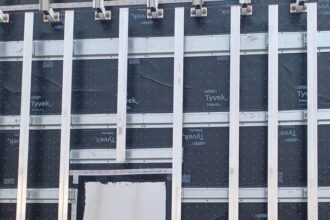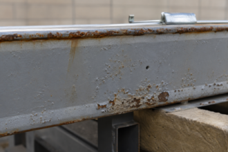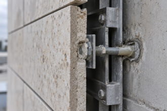
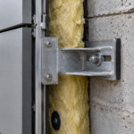
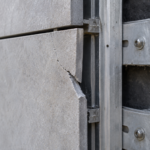


- Snap-lock seams rely on gravity and friction to stay engaged, making them structurally unreliable when used in vertical wall applications.
- ASCE 7-22 corner zone wind pressures can exceed 80 psf in coastal exposures, more than double what most roofing submittals calculate for.
- Mechanically seamed profiles resist seam disengagement loads exceeding 200 pounds-force per linear foot compared to 40 to 80 for snap-lock systems.
- Extending a roofing submittal to cover wall cladding without separate calculations and wall-orientation test data is a specification error with real consequences.
- Specifying mechanically seamed panels for wall applications above 30 feet in high-wind exposures adds 15 to 25 percent in panel installation cost and avoids far greater remediation costs.
Snap-Lock vs. Mechanically Seamed Panels at Walls
Two Systems, One Common Mistake
Snap-lock standing seam panels rely on panel-to-panel mechanical interlock maintained by gravity and friction. The male leg snaps over the female leg to a fixed engagement depth and the system performs as designed when panels hang vertically from clips and gravity keeps the seam seated.
Mechanically seamed profiles work differently: a field seaming tool folds both panel legs together to 180 or 360 degrees, creating a positive mechanical interlock that does not depend on friction or orientation to maintain engagement.
Both systems originate as roofing products. Both get specified into wall applications every week on commercial projects across the country, often without any re-evaluation of profile geometry, clip spacing or seam capacity under wall-specific load conditions.
That is the mistake this article addresses.
The MBMA Metal Roofing Systems Design Manual distinguishes between the structural roles of roof panels and wall panels explicitly. Roof panels resist gravity load and uplift.
Wall panels resist out-of-plane wind pressure acting perpendicular to the panel face. In a wall application, gravity no longer assists seam engagement.
Wind load creates out-of-plane tension that snap-lock seams were not engineered to resist. This is a structural and water management decision.
Treating it as a product preference is how you end up with 340 linear feet of disengaged panels on a six-story building in coastal South Carolina.
The distinction between the two systems is not subtle once you understand the load path. A snap-lock seam that performs without incident on a 4:12 roof slope in an inland exposure category will see a fundamentally different load environment when the same profile is run vertically up a parapet wall in Exposure Category D.
The geometry has not changed. The physics has.
Gravity, which kept the seam seated and transferred load predictably through the clip to the substrate, is now acting parallel to the panel face rather than perpendicular to it. Every pound of out-of-plane wind pressure that acts on that wall panel must now travel through the seam engagement alone.
That is a load path the snap-lock profile was not tested to carry at the engagement depths and clip spacings typically specified from a roofing submittal.
What ASCE 7-22 Changed and Why It Matters Here
ASCE 7-22 revised the wind speed maps in Figure 26.5-1B for Risk Category II structures, increasing design wind speeds in coastal and transitional exposure categories across much of the Southeast, Gulf Coast and mid-Atlantic regions. Those increases flow directly into components and cladding (C&C) pressure calculations and the wall-to-roof transition zone sits precisely where the pressure coefficients are highest.
Section 30.3 of ASCE 7-22 governs C&C for low-rise buildings with mean roof height at or below 60 feet. Section 30.5 governs taller structures.
In both cases, corner and edge zones carry GCp values that run two to three times the field zone values. A wall assembly at a parapet transition on a coastal mid-rise sits in one of those high-pressure zones by definition.
The design pressures there are not marginal increases over field conditions; they represent a fundamentally different load environment.
The compliance gap is this: field specifications for wall cladding at transition zones are still being written from roofing submittals. A roofing submittal showing clip spacing at 24 inches on center was calculated for roof C&C pressures, not wall C&C corner zone pressures.
Recalculating for the actual wall application frequently requires 12-inch clip spacing or closer. That recalculation almost never happens when a contractor simply extends the roofing system up the wall without re-engaging the engineer of record.
To put specific numbers behind that gap: a Risk Category II building at 45 feet mean roof height in Exposure Category D, using ASCE 7-22 Section 30.3, will produce a corner zone GCp of approximately negative 2. 8 for the wall surface.
At a design wind speed of 160 mph, that translates to a design pressure exceeding 80 psf in the corner zone. The same building’s roof field zone might generate a GCp of negative 1.0, producing a design pressure closer to 30 psf.
A clip spacing and seam capacity that was calculated for 30 psf and then carried forward to a wall corner zone at 80 psf is not a conservative specification. It is an unconservative one by a factor that exceeds two.
The engineer of record who signed the roofing submittal did not sign off on that wall condition and the contractor who extended the panel run up the parapet did not know to ask.
ASCE 7-22 tightened the requirements. The field hasn’t caught up.
That gap is where failures initiate.
Seam Mechanics Under Out-of-Plane Load
The load path in a vertical wall panel assembly runs from panel face to seam engagement to clip to substrate framing. In a roof application, gravity keeps panels seated against clips and seam engagement is supplementary.
In a wall application, the seam is the primary load transfer mechanism. It must actively resist tension every time wind pressure acts on the panel face.
Snap-lock seam geometry creates a specific failure risk in this load path. The male leg engages the female leg to a fixed depth, typically between one and one-and-a-half inches depending on the profile.
Under sustained or cyclic out-of-plane tension, that engagement can release progressively along the seam length. The failure mode is commonly described as “zipper” failure: once a section of seam disengages, the released panel geometry concentrates load on the adjacent engaged section, which then disengages in sequence.
There is no mechanical feature in the snap-lock profile that arrests this progression. Published snap-lock seam disengagement loads from manufacturer test data typically range from 40 to 80 pounds-force per linear foot.
Mechanically seamed profiles behave differently under the same loading. The field seaming tool folds both panel legs together and separation requires the metal itself to yield or tear.
The seam does not disengage; it fails. That distinction matters for structural reliability.
Published mechanically seamed seam engagement values in manufacturer test data routinely exceed 200 pounds-force per linear foot and in many cases exceed the clip pull-through capacity of the substrate connection.
The cyclic loading dimension of this problem deserves more attention than it typically receives in submittal review. A single wind event that loads a snap-lock seam to 70 percent of its disengagement threshold may not produce visible failure.
Ten wind events at that load level or a sustained gust that holds the panel in tension for several seconds, can progressively reduce the effective engagement depth through micro-displacement at the seam interface. The panel looks installed.
The seam looks engaged. The effective engagement depth has decreased by a measurable amount and the next storm event starts from a compromised baseline.
This degradation mechanism does not appear in static test data, which is one reason ASTM E1592 cyclic testing protocols matter more for wall applications than static pressure test results alone.
Two additional points deserve attention. First, FM Approvals 4471 is a roof-specific approval standard.
FM approval for a panel system does not transfer to wall applications. Second, ASTM E1592 tests structural performance of sheet metal roof and siding systems under uniform static air pressure difference, but test orientation matters.
If wall-orientation testing was not explicitly requested and documented in the submittal, the test data does not support the wall application claim.
Water Management at the Transition Detail
The wall-to-roof transition concentrates three distinct water infiltration risks simultaneously: a change in panel orientation, a reversal of drainage direction and a termination or penetration condition. Managing any one of those risks in isolation is straightforward.
Managing all three at the same location, with the same panel profile, requires deliberate detailing that most roofing submittals do not address.
Snap-lock seam geometry creates a specific water management liability at vertical orientations. The seam cap is not mechanically closed; it relies on the snap engagement to maintain the profile geometry.
That open-top condition creates a capillary pathway under wind-driven rain. On a roof, water drains away from the seam and gravity works in your favor.
On a wall, water runs along the seam length. The capillary gap does not drain; it collects.
Mechanically seamed profiles eliminate that pathway. The folded seam closes the capillary gap and when combined with a sealant bead at the seam during the double-lock operation, the assembly meets the water infiltration test thresholds in AAMA 508-07 for pressure-equalized rain screen wall cladding systems.
That combination of mechanical closure and sealant is best practice, not a code requirement, but it is the only configuration I would accept on a wall application in IECC Climate Zones 4 through 7 or in any coastal exposure category.
Flashing integration at the transition requires a continuous cleat or receiver, a back-pan or secondary drainage plane and a properly lapped membrane tie-in to the air and water control layers below. SMACNA’s Architectural Sheet Metal Manual, 8th Edition, details these transition conditions.
The complication with snap-lock profiles is that seam height and cap geometry vary depending on engagement state, which makes consistent receiver sizing and flashing lap geometry difficult to maintain across the transition length. ASTM E331 water penetration testing of the completed assembly, not just the panel system in isolation, is the only way to verify that the transition detail performs as designed.
The back-pan requirement is worth stating plainly because it gets value-engineered out of projects with regularity. A back-pan or secondary drainage plane behind the panel system at the transition zone is not a redundancy feature added for conservatism.
It is the primary defense against water infiltration at the one location where the panel system is most likely to admit water. At a parapet transition, the panel terminates, the flashing changes direction and the air pressure differential across the assembly is at its highest.
Any water that enters the seam at that location has a direct path to the substrate if no drainage plane exists behind the panel. The SMACNA details show the back-pan extending a minimum of 4 inches behind the panel face and lapping over the membrane below by at least 6 inches.
Those dimensions are minimums, not targets.
Clip Selection and Substrate Compatibility
Clip selection at wall applications fails more often through substrate incompatibility than through incorrect clip type. Both snap-lock and mechanically seamed systems use floating or fixed clips and the choice between them affects thermal movement accommodation.
That is the conversation most specifications address. The conversation that gets skipped is clip pull-through and pull-over capacity at the specific substrate under wall-specific load combinations.
A clip fastened into a steel hat channel at 24 inches on center carries a different pull-through value than the same clip fastened into 7/16-inch OSB sheathing or into a concrete substrate with powder-actuated fasteners. Each substrate requires tested values, not interpolated assumptions from roofing applications.
The load combination for wall C&C in a corner zone under ASCE 7-22 may exceed the tested pull-through capacity of the clip-fastener-substrate assembly even when the seam itself is adequate.
Fixed clips restrict thermal movement and create stress concentrations in long panel runs. Floating clips accommodate movement but reduce the effective engagement between clip and panel leg under out-of-plane tension.
At wall applications, where out-of-plane load is the governing condition, the tradeoff between movement accommodation and clip engagement capacity requires explicit engineering review. Defaulting to the clip specified in the roofing submittal without that review is a specification error, not a field error.
The substrate compatibility issue becomes particularly consequential when wall framing systems change across the building elevation. A project that uses cold-formed steel stud framing at the lower wall and transitions to a steel moment frame with intermittent girts at the upper wall will present two different substrate conditions to the same panel system.
The clip pull-through value for a #14 screw into 18-gauge cold-formed steel stud at 16 inches on center is not the same as the pull-through value for the same fastener into a 12-gauge girt at 36 inches on center. Both conditions may appear on the same elevation.
The specification needs to address both explicitly, with tested values for each, rather than citing a single clip and fastener specification that was derived from the roofing submittal and applied uniformly across a substrate condition that is not uniform. When the engineer of record is not re-engaged to review the wall-specific clip and fastener schedule, that differentiation does not happen.
The Specification-to-Field Gap in Practice
The failure pattern I described in the opening is not unusual. What makes it instructive is that the manufacturer’s installation manual explicitly limited snap-lock panel use in vertical wall applications above a certain height and wind exposure.
The limitation was in the document. The specifier did not read it or did not apply it and the contractor had no reason to question a specification that came from the project architect.
This is the specification-to-field gap at its most consequential. The engineer of record calculated roof C&C pressures and specified a roofing system that met those pressures.
The wall application at the parapet transition was treated as an extension of that roof specification rather than as a separate cladding assembly with its own load conditions, attachment requirements and water management demands. No one recalculated.
No one requested wall-orientation test data. No one verified clip pull-through values for the specific substrate at the wall location.
The fix is procedural as much as technical. Wall applications of metal panel systems at transition zones require a separate specification section, separate structural calculations referenced to ASCE 7-22 wall C&C provisions for the correct zone classification and separate submittal review that includes wall-orientation test data under ASTM E1592. If the panel system manufacturer cannot provide wall-orientation test data, that is a disqualifying condition for the application.
Not a concern to note in the RFI log.
The procedural fix also requires a defined handoff point between the roofing specification and the wall cladding specification. On projects where a single metal panel product is used across both the roof and the wall, the specification writer often treats the two applications as one continuous system and writes a single specification section referencing the roofing submittal for both.
That single-section approach is where the gap opens. The division between CSI MasterFormat Section 07 41 13 for metal roof panels and Section 07 42 13 for metal wall panels exists for a reason.
Using it correctly means writing two specifications, requesting two sets of test data and requiring two separate submittal reviews with the engineer of record engaged on both. On projects where that process adds cost or schedule pressure, the alternative is a post-storm forensic investigation that costs considerably more than the submittal review would have.
Making the Right Call Before the Panels Go Up
The practical recommendation is direct: specify mechanically seamed profiles for any metal panel wall application above 30 feet in Exposure Category C or D, at any parapet or wall-to-roof transition in coastal or high-wind regions and at any location where the C&C corner or edge zone GCp values under ASCE 7-22 Section 30.3 or 30.5 exceed the tested seam disengagement capacity of the snap-lock profile being proposed.
Snap-lock systems are cost-effective and fast to install. Those are real advantages in the right application.
A low-slope roof assembly in a protected inland exposure is the right application. A six-story parapet wall transition in coastal South Carolina is not.
The installed cost difference between snap-lock and mechanically seamed profiles on a wall application is real but bounded. Field seaming equipment adds mobilization cost and the double-lock operation adds labor time per linear foot of seam.
On a typical commercial wall application, that difference runs between 15 and 25 percent of the panel installation cost, not the total wall assembly cost. Against the total project cost, the premium is small.
Against the cost of panel replacement, water damage remediation, forensic investigation and potential litigation following a storm event, it is not a comparison worth making. The mechanically seamed profile costs more to install and performs reliably under the load conditions the wall will actually see.
That is the calculation the specification needs to reflect before the panels go up, not after the first significant storm reveals what the snap-lock seam could not hold.
The seam capacity gap between snap-lock and mechanically seamed profiles is not a marginal difference that careful detailing can bridge. It is a fundamental difference in how the two systems transfer load.
Wind events in coastal exposure categories will eventually load that seam to its limit. The question the specification needs to answer before installation, not after the first significant storm, is which system was designed to hold.