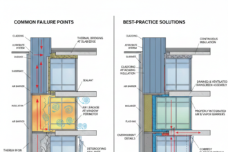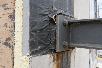
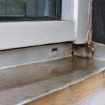
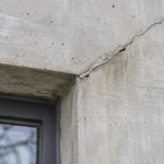
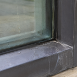
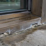
- Continuous ribbon glazing creates a repeatable water intrusion failure mode where sill pans terminate against exposed slab edges.
- Contractual splits between Division 07 and Division 08 leave the sill pan-to-slab edge transition unowned by either subcontractor.
- Water enters through three distinct pathways including direct drainage, condensate migration and anchor pocket infiltration.
- Current standards from AAMA, NRCA and IBC contain no prescriptive compliance pathway for this specific transition condition.
- A constructible solution integrates a fluid-applied membrane bridge, termination bar and two-stage drainage configuration specified across both divisions.
Why Ribbon Windows and Slab Edges Are a Collision Course
Continuous ribbon glazing has become the default exterior expression for mid-rise Type I and II construction across the mid-Atlantic, Southeast and Mountain West. Energy code daylighting credits under ASHRAE 90.1-2022 and the architectural preference for horizontal massing have made floor-to-ceiling or deep-band fenestration nearly ubiquitous in mixed-use and multifamily work.
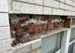
That proliferation is generating a repeatable water intrusion failure mode at the slab edge and it is showing up in forensic reports with increasing frequency.
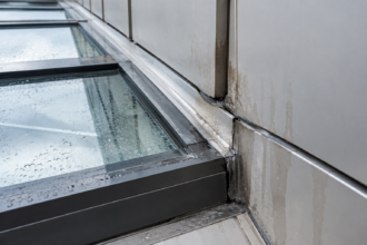
The geometry is the problem. A continuous ribbon window assembly imposes a horizontal sill pan drain plane directly against an exposed vertical concrete face.
There is no natural ledge, no counterflashing receiver, no recess cast into the slab. The sill pan must terminate somewhere and that somewhere is one of the most geometrically hostile conditions in the building envelope.
The contractual structure compounds the geometry. Glazing systems are bid under Division 08 and waterproofing under Division 07. Neither subcontractor’s scope explicitly owns the transition zone between those two systems.
AAMA 501.2 field testing validates the glazing system in isolation; it does not test the slab edge transition. Construction documents routinely resolve this with a note reading “coordinate with waterproofing contractor.
” That note is not a detail. It is a liability transfer.
Anatomy of the Sill Pan Assembly at a Slab Edge
A properly configured sill pan assembly consists of a formed metal pan with a positive slope toward the exterior, end dams at each jamb, weep holes at the pan face, a back leg flashing that integrates with the wall water control layer and a front lip that directs drainage away from the slab edge face. In a standard punched opening condition, the back leg laps over the WRB below the rough opening and the drainage path is continuous.
The slab edge condition breaks that logic entirely.
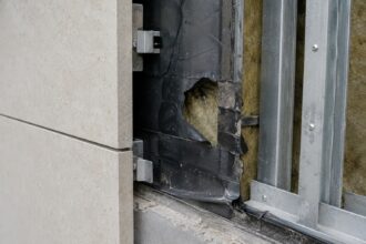
At the slab edge, the pan typically terminates at or slightly inboard of the concrete face. The slab edge itself is coated with a fluid-applied or sheet-applied waterproofing membrane that terminates at the slab soffit or fascia.
Those two systems, the sill pan drain plane and the slab edge coating, approach each other from perpendicular directions and stop. The horizontal-to-vertical membrane handoff is where water finds its path into the substrate.
The sealant joint at the pan-to-slab interface is governed by ASTM C1193, which addresses joint design, substrate preparation and sealant selection. ASTM C1193 does not address membrane continuity across the transition.
A sealant joint is not a membrane. It is a point seal subject to UV degradation, thermal cycling and differential movement between the glazing system framing and the concrete structure.
Relying on that joint as the sole water control element at the slab edge is a design error, not a field improvisation.
What makes this anatomy particularly unforgiving is the cumulative tolerance stack between the glazing system anchor clips and the cast concrete slab edge. Structural concrete tolerances under ACI 117 permit plus or minus three-eighths of an inch on formed slab edges.
Curtain wall anchor systems carry their own fabrication and installation tolerances. The combined result is a field condition where the gap between the sill pan back leg and the concrete face varies along the run of a ribbon window, sometimes by a half inch or more within a single bay.
A sealant joint that is correctly sized and tooled at one location may be over-extended or bridged at the next anchor point. Membrane continuity across that variable gap requires a material with sufficient elongation to accommodate the worst-case condition at every point along the run, not just at the locations a field crew happened to measure during installation.
The Ownership Gap: Contractual and Coordination Failures
The glazing contractor’s scope ends at the sill pan assembly. The waterproofing contractor’s scope ends at the slab edge coating or the below-grade membrane termination.
CSI MasterFormat 2016 reinforces this split structurally: Division 07 covers thermal and moisture protection, Division 08 covers openings. The physical gap in the field mirrors the organizational gap in the specification.
Neither contractor has a contractual obligation to detail the transition and neither typically does.
General contractor coordination meetings rarely include a specific agenda item for the sill pan-to-slab edge transition. When a field crew encounters the condition, the typical response is an RFI.
The typical RFI response is “coordinate in field. ” That response is not acceptable on an envelope assembly where the failure mode is latent and the repair cost is orders of magnitude higher than the cost of a proper detail.
Shop drawing review by the envelope consultant is the last reliable checkpoint before installation. This is where the failure can be caught.
The glazing submittal will show the sill pan in section but will not show the slab edge membrane termination. The waterproofing submittal will show the slab edge coating but will not show the sill pan.
Neither submittal contains the transition detail because neither contractor drew it. The envelope consultant reviewing those submittals independently, without overlaying them against each other, will miss the gap every time.
The fix at the submittal stage is straightforward: require both subcontractors to submit a coordinated transition detail as a condition of approval. That requirement has to be written into the specification.
It will not happen organically.
The scheduling dimension of this ownership gap compounds the problem in ways that are rarely discussed in specification language. On a typical mid-rise project, the waterproofing contractor installs the slab edge coating during the concrete protection and drainage phase, often six to ten weeks before the glazing contractor mobilizes.
By the time the sill pan is installed, the slab edge membrane is already in place, its termination edge is already set and the waterproofing contractor has moved to the next floor or demobilized entirely. Asking those two contractors to coordinate a transition detail after the fact is not a coordination problem.
It is a sequencing problem that was created at the specification stage and can only be solved at the specification stage. The Division 07 specification section for slab edge waterproofing must explicitly require the waterproofing contractor to leave a minimum uncoated substrate width at the sill pan back leg location, protected with a temporary cover, for membrane integration by the glazing contractor or a designated applicator.
Without that language, the waterproofing contractor has no reason to leave anything and every reason to terminate cleanly at the most convenient stopping point.
Failure Mechanics: How Water Actually Enters
The primary pathway is direct. Wind-driven rain contacts the sill pan, travels to the weep holes and exits at the slab edge face.
Without a continuous membrane connecting the pan drain plane to the slab edge coating, that water contacts unprotected concrete substrate and wicks laterally via capillary action. The rate of capillary uptake in normal-weight concrete is not trivial; it is fast enough to saturate the slab edge in a single significant rain event.
The secondary pathway is slower and less obvious. Condensation forms on the underside of the metal sill pan, particularly in IECC climate zones 4 through 7 where indoor-outdoor temperature differentials are sustained across the heating season.
That condensate accumulates at the back leg of the pan and migrates inboard along the slab edge if no positive drainage slope or membrane termination bar is present. Interior drywall damage from this pathway is frequently misdiagnosed as roof drainage or plumbing.
Freeze-thaw cycling accelerates the failure. Concrete at the slab edge is exposed on three faces: the vertical fascia, the horizontal soffit and the top surface beneath the sill pan.
Moisture that enters the substrate cycles through freeze-thaw repeatedly in zones 4 through 7, opening micro-cracks that become preferential water pathways. ASHRAE 90.1-2022 climate zone mapping correlates directly with the geographic distribution of this failure mode.
The latency of the failure is what makes it forensically difficult. Water intrusion at the slab edge typically does not manifest as interior damage for 12 to 24 months post-installation.
By that point, the glazing contractor and waterproofing contractor have demobilized and their warranty periods are running. ASTM E2128 provides the standard forensic methodology for diagnosing the failure pathway, including flood testing, tracer dye injection and sequential disassembly.
In the forensic investigations I have conducted on this condition, the slab edge substrate has been consistently saturated well beyond the visible staining line.
A third pathway that receives almost no attention in the literature is interstitial migration through the anchor pocket. Curtain wall and storefront systems at ribbon window applications are anchored to the slab edge through cast-in channels or post-installed anchors that penetrate the slab edge face.
Each anchor penetration is a potential water entry point if the pocket is not sealed and back-filled with a compatible material before the sill pan is set. In practice, anchor pockets are frequently left open or filled with non-sag polyurethane foam that is not rated for continuous water exposure.
Foam at an anchor pocket is a capillary wick, not a seal. Water that enters the anchor pocket migrates inboard along the anchor shaft and appears at the interior face of the slab edge, sometimes three to four inches from the exterior face, in a location that looks nothing like a glazing leak.
Diagnosing this pathway without opening the assembly requires tracer dye injection at the anchor pocket under ASTM E2128 protocols, a step that is often skipped because the investigator assumes the primary pathway is at the sill pan face.
What Current Standards and Details Get Wrong
AAMA 2400 and the AAMA 501 series address glazing system performance in detail. They contain no prescriptive guidance for slab edge membrane integration.
The NRCA Roofing Manual and waterproofing guidelines address slab edge conditions in plaza deck and below-grade contexts but do not address the ribbon window sill pan transition. IBC 2021 Section 1402 requires exterior walls to resist moisture intrusion but provides no prescriptive compliance pathway for the sill pan-to-slab edge condition.
Performance intent without a compliance pathway means every project team invents its own solution.
That vacuum gets filled by field improvisation. The most common substitutes I observe in forensic investigations are field-applied sealant beads at the pan-to-slab joint, uncured butyl tape pressed into the gap and backer rod installed without a bond breaker.
These are not details. They are temporary patches applied by crews who were never given a real drawing.
They fail within two to three years under normal thermal cycling and UV exposure.
The absence of a dedicated industry detail for this condition is not a gap waiting to be filled by the next code cycle. It is an active problem generating real failures on real buildings right now.
AAMA, NRCA and the waterproofing industry need a joint technical committee focused specifically on fenestration-to-slab edge transitions in ribbon window applications. Until that guidance exists, the envelope consultant is the only line of defense.
The standards gap is particularly consequential when a project pursues third-party envelope testing under AAMA 501.2 or ASTM E1105. Both test protocols pressurize the glazing system and verify that water does not pass through the framing assembly.
Neither protocol requires the test chamber to span the slab edge transition. A glazing system can pass AAMA 501.2 field testing with a completely unprotected slab edge transition immediately below the test zone.
The test report goes into the project file as evidence of performance compliance and the owner has no reason to question it. When water intrusion is discovered 18 months later, the glazing contractor correctly points to the passing test report.
The waterproofing contractor correctly points to a clean membrane termination. The damage sits in the 4 inches between those two systems and neither test protocol was ever designed to find it.
Expanding the AAMA 501.2 test chamber requirement to include the slab edge transition zone would close this gap without requiring a new standard. It requires only a revision to the test protocol’s chamber boundary definition, which is a committee-level decision that could be implemented in the next revision cycle.
A Constructible Detail That Actually Works
The transition detail that performs in this condition integrates three elements: a fluid-applied membrane bridge, a metal termination bar and a two-stage drainage configuration. The fluid-applied membrane, selected for compatibility with both the sill pan substrate and the slab edge coating, is applied continuously from the back leg of the sill pan across the slab edge face to the soffit termination.
Minimum lap onto each substrate is 3 inches; 4 inches is better on concrete where surface irregularities are common.
The termination bar mechanically fastens the membrane at both the pan back leg and the slab edge fascia, providing a positive stop against wind uplift and thermal movement. The fastener pattern and edge distance must account for the concrete substrate condition; spalled or carbonated concrete at the slab edge face requires surface preparation before the membrane is applied and that prep step is almost never included in the waterproofing specification.
The two-stage drainage configuration positions the primary weep at the sill pan face and a secondary weep at the slab edge fascia, below the membrane termination bar. If water breaches the primary seal, it drains at the fascia rather than into the substrate.
This is not a redundant system in the marketing sense. It is a recognition that single-stage drainage at a geometrically complex condition is insufficient.
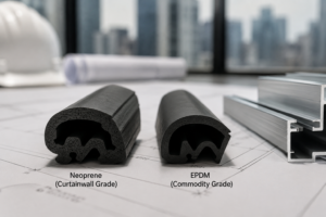
Specify the membrane by performance criteria, not by generic category. Require elongation of at least 200 percent at low temperature per ASTM C719 cycling, adhesion to both metal and concrete substrates without primer failure and UV resistance for exposed fascia conditions.
Write the transition detail into both the Division 07 and Division 08 specifications with a cross-reference. Make both subcontractors responsible for the transition detail in their respective scopes.
Material selection for the fluid-applied bridge membrane deserves more specification attention than it typically receives. The sill pan back leg is aluminum or galvanized steel.
The slab edge face is concrete, frequently with a form release agent residue that was inadequately cleaned before the waterproofing contractor arrived. Those two substrates have different surface energies, different thermal expansion coefficients and different surface preparation requirements.
A single-component polyurethane membrane that bonds well to primed concrete may peel from unprimed aluminum within one heating season. A silicone-modified membrane that accommodates the thermal movement of the metal pan may not achieve the adhesion values required on a carbonated concrete fascia.
The specification must require the membrane manufacturer to confirm compatibility and adhesion to both substrates in writing, with primer requirements called out explicitly for each. That confirmation should be submitted as part of the coordinated transition detail resubmittal, not obtained verbally in the field on the day of installation.
The Consultant’s Role at the Submittal Stage
Catching this failure before it is built requires a specific review protocol. When glazing and waterproofing submittals arrive, overlay the sill pan section drawing against the slab edge membrane termination drawing at the same scale.
If the transition is not shown on both drawings, reject both submittals. Do not return them with a comment requesting coordination.
Reject them and require a coordinated transition detail as a resubmittal condition.
This is not an unreasonable standard. It is the minimum required to close the gap that the specification created by splitting the scope across two divisions.
The glazing contractor and waterproofing contractor will resist this requirement initially because it forces them to coordinate before they are on site. That resistance is the point.
Coordination at the submittal stage costs hours. Coordination after water intrusion is discovered costs hundreds of thousands of dollars and ends in litigation where no one wins cleanly.
The forensic record on this failure mode is clear and consistent. The glazing system passes its field test.
The waterproofing membrane terminates cleanly. The damage occurs in the 4 inches between those two systems that no one detailed.
The envelope consultant who reviews submittals independently, approves them independently and then walks away has not done the job. The transition detail is the job.
The submittal review protocol should also extend to the mock-up stage. IBC 2021 and most project specifications require a full-scale exterior wall mock-up for mid-rise construction.
That mock-up almost always includes a ribbon window bay. It almost never includes a correctly detailed slab edge transition, because the mock-up drawing is prepared by the glazing contractor and the slab edge is treated as a support-of-excavation condition rather than an envelope assembly.
Requiring the mock-up to replicate the slab edge transition detail, including the fluid-applied membrane bridge, termination bars and secondary weep, gives the envelope consultant a physical assembly to inspect before the detail is repeated across every floor of the building. A mock-up that does not include the transition detail is not a mock-up of the actual assembly.
It is a mock-up of the easy part. The consultant’s scope of services agreement should explicitly include mock-up review at the slab edge transition as a billable observation task, with a written field report documenting conformance or deficiency.
That documentation protects the consultant and creates a record that the transition detail was either correctly installed or flagged before the building was enclosed.