- Infrared thermography consistently reveals continuous thermal anomalies at skylight curb-to-wall junctions that no contractor was assigned to seal.
- Three separate subcontractors each stop at their scope boundary leaving a critical air barrier gap that no specification section addresses.
- ASHRAE 90.1-2022 requires continuous air barrier coverage at skylight curbs but most compliance submittals omit or defer the transition detail entirely.
- Uninsulated aluminum curb upstands create measurable linear thermal bridges that degrade wall assembly performance and cause interior condensation misdiagnosed as roof leaks.
- Correcting an undetailed skylight curb transition after occupancy costs ten times more than drawing the coordination detail correctly before construction begins.
Glazed Skylight-to-Vertical-Wall Transitions: The Air Barrier Handoff Nobody Draws Correctly
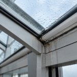
During a third-party envelope commissioning review on a four-story institutional office building, an infrared thermography scan conducted at 15°F delta-T revealed a continuous thermal anomaly running the full perimeter of a 12-foot-wide barrel vault skylight. The anomaly was not at the glazing unit itself.
It ran along the 8-inch aluminum curb upstand where it met the interior gypsum-sheathed wall assembly. The roofing contractor had terminated their self-adhered membrane at the base of the curb.
The curtainwall contractor had stopped their fluid-applied air barrier at the sill receptor. Nobody had drawn or built, the 6-inch gap between them.
That gap was open to the interior conditioned space across the full 40-foot perimeter of the skylight. Nobody owned it.
Nobody fixed it until the commissioning agent put it in writing.
That scenario is not unusual. It is the rule.
Why the Skylight Curb-to-Wall Junction Is a Chronic Documentation Gap
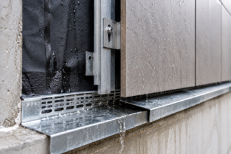
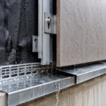
The physical transition zone at a commercial skylight curb involves three distinct assembly conditions arriving at the same 6-to-8-inch vertical upstand: the roof membrane assembly below, the glazing system above and the vertical wall assembly on the interior face. Each of those conditions belongs to a different subcontractor.
The roofing contractor typically owns the curb flashing and counter-flashing. The curtainwall or glazing contractor owns the sill receptor, the thermal break within the skylight system and the glazing unit itself.
The wall contractor owns the air and vapor control layers on the vertical face of the framing assembly. None of them owns the transition between their scope and the next contractor’s scope.
This is a contractual no-man’s-land and shop drawing review processes almost never close it. Roofing submittals show the curb flashing terminating at the base of the upstand.
Curtainwall submittals show the sill receptor starting at the top of the upstand. Wall submittals show the fluid-applied WRB stopping at the rough opening framing.
No submittal shows what connects them. No specification section typically assigns that connection to a responsible party.
The submittal review process, which is designed to confirm that individual scope packages conform to contract documents, cannot identify a gap that the contract documents themselves never addressed. The reviewer approves each submittal against its own scope and the gap persists, invisible in the paper record until the building is pressurized or scanned.
NIBS Guideline 3 (Building Enclosure Commissioning) identifies transition zones between dissimilar assemblies as the highest-frequency location for air barrier discontinuities found in post-occupancy reviews. That finding is consistent with what field investigation confirms again and again.
The problem is not technical ignorance. The problem is that nobody is contractually required to solve it.
Experienced roofing foremen know where their scope ends. Experienced glazing installers know where their scope ends.
The gap between those two endpoints is not ignorance on either side. It is a documentation failure that originates at the design and specification stage and propagates forward into construction without correction.
What ASHRAE 90.1-2022 and IBC Energy Provisions Now Require at Skylight Curb Assemblies
ASHRAE 90.1-2022 Section 5. 4.
3. 1 requires a continuous air barrier across all envelope assemblies, explicitly including transitions at roof penetrations.
The skylight curb is a penetration through the thermal envelope. It is not a rooftop accessory.
That distinction matters for compliance documentation. A skylight system that sits on a curb that penetrates the roof plane is, by definition, a discontinuity in both the air barrier and the thermal control layers of the envelope.
The code requirement for continuity applies at that penetration with the same force it applies at a wall-to-roof transition or a foundation-to-wall transition. Treating the skylight as a glazing product selection rather than an envelope penetration detail is the design decision that produces the documentation gap downstream.
Section 5.4.3.1.1 defines material-level compliance thresholds for air barrier materials at a maximum of 0. 004 cfm/ft² at 0.3 in.
w. g.
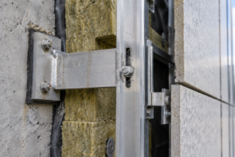
Extruded aluminum, the standard curb upstand material in commercial skylight construction, does not meet that definition as an air barrier material. It is airtight at the material level but it is not detailed or connected as a continuous air barrier component.
The upstand is a structural element. Treating it as an air barrier requires deliberate transition detailing at both its base and its perimeter connection to the wall assembly.
The aluminum extrusion has no lap, no adhesion to adjacent materials and no accommodation for the differential movement that occurs between the curb and the wall framing. Calling it an air barrier because it does not have holes in it is the kind of reasoning that produces commissioning findings.
IBC 2021 Section 1322.1 references the ASHRAE 90. 1 air barrier requirements by adoption in most jurisdictions, though local amendments vary.
COMcheck compliance documentation and California Title 24 energy compliance submittals increasingly require air barrier continuity diagrams as part of the permit package. In practice, most submitted packages either omit the skylight curb transition entirely or show it as a single arrow labeled “coordinate with roofing contractor.
” That is not a detail. It is a liability transfer.
Title 24 compliance reviewers in California have begun flagging skylight curb transitions specifically in the NRCC-ENV forms when the air barrier continuity diagram shows a gap or an unresolved coordination note at the curb base. That enforcement trend is moving into other jurisdictions as energy code compliance review becomes more technically specific.
Getting ahead of that review cycle requires drawing the transition before the permit submittal, not after the first plan check comment.
Anatomy of the Failure: How Curb Flashing Discontinuities Develop
The construction sequence creates the problem before anyone realizes it. The roof membrane goes down first.
The curb is set, the self-adhered base flashing is applied to the curb face and the counter-flashing is installed. At this point, the air barrier layer on the curb face exists.
Then the glazing contractor sets the sill receptor and installs the skylight system. Then the wall contractor closes the interior framing, applies sheathing and installs the fluid-applied WRB on the vertical wall face.
By the time the wall scope reaches the rough opening at the curb base, the roofing scope has been complete for weeks. Nobody laps the wall WRB onto the curb face.
The connection never gets made.
Three physical failure modes account for the majority of the discontinuities I have documented. First: the self-adhered membrane terminates at the curb base without a transition strip connecting it to the wall WRB or air barrier.
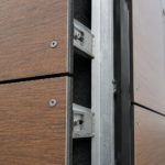
Second: the fluid-applied air barrier on the wall assembly stops at the rough opening framing without wrapping onto the curb upstand face. Third: the sill receptor end dams are present for water management but are not detailed or sealed as air barrier components at the receptor-to-curb interface.
Each of these failure modes is independently capable of producing a measurable air leakage path. When all three occur simultaneously, which they frequently do, the cumulative leakage area at the skylight perimeter can exceed the combined air leakage area of the glazing units themselves.
That inversion, where the frame and curb assembly leaks more than the glass, is counterintuitive to building owners and facility managers who focus their maintenance attention on the glazing.
Differential movement compounds every one of these failures. The curb assembly and the wall framing move independently under thermal cycling and structural loading.
A rigid transition connection at this joint will crack. ASTM E1186 protocols for air leakage site detection and ASTM E783 field measurement of air leakage through installed fenestration are both applicable here, but E783 is almost always applied to the glazing unit as the test boundary.
The curb-to-wall perimeter joint is rarely defined as a discrete test boundary. That omission means the failure mode goes unmeasured even when field testing occurs.
Specifying E783 with an explicit test boundary definition that includes the curb-to-wall perimeter joint, not just the glazing unit, would capture this failure mode in the acceptance testing record. Almost no project specification does that.
Thermal Bridge Accumulation at the Upstand: What the Numbers Actually Show
Linear thermal transmittance, expressed as a psi-value in W/(m·K), describes the heat loss per unit length at a thermal bridge. At the skylight curb upstand, the psi-value is additive across the full perimeter of the skylight.
A 40-foot perimeter skylight with an uninsulated aluminum upstand connection to steel stud wall framing does not have a point thermal bridge problem. It has a continuous linear thermal bridge problem.
The distinction between point and linear thermal bridges matters for energy modeling accuracy. Point thermal bridges are typically addressed through area-weighted adjustments in the assembly U-factor calculation.
Linear thermal bridges require explicit psi-value inputs in the energy model and most energy models submitted for permit compliance do not include them at skylight curb locations.
ISO 10211 and THERM 7.x finite element modeling of aluminum curb upstand connections to steel stud framing consistently produce linear thermal transmittance values in the range of 0. 25 to 0.45 W/(m·K) depending on insulation continuity at the upstand.
Oak Ridge National Laboratory building envelope thermal bridging research has documented similar ranges for aluminum-to-steel framing connections without continuous insulation at the interface. At 0.35 W/(m·K) across a 12-meter perimeter, the heat loss contribution from the upstand connection alone is thermally significant relative to the effective R-value of the adjacent wall assembly.
A wall assembly with a nominal R-20 continuous insulation layer and R-13 cavity insulation may have an effective whole-assembly R-value in the range of R-16 to R-17 after accounting for framing fraction. Adding an uninsulated aluminum curb perimeter running the full length of that wall segment degrades the effective thermal performance of the adjacent assembly in a way that does not appear in the energy model and does not appear in the compliance documentation.
The thermal break within the curtainwall or skylight system is engineered for the glazing load path. Manufacturers certify and publish that data.
What no manufacturer publishes is the thermal performance of the curb base connection to the wall framing, because that connection is not part of their scope. It appears in no submittal and in no energy model.
The result is a systematic underestimation of effective envelope thermal performance at every skylight installation that uses this assembly configuration. Correcting this in the energy model requires the envelope consultant to run the THERM simulation independently, using the actual curb geometry and framing connection detail and input the resulting psi-value as a linear thermal bridge in the whole-building energy model.
That step is rarely taken and rarely required by the authority having jurisdiction, but it is the only way to produce an energy model that reflects what the building will actually perform.
The hygrothermal consequence is direct. Interior surface temperatures at an uninsulated aluminum upstand in IECC Climate Zones 5 through 7 routinely fall below the dew point of interior air at normal occupancy humidity levels.
Condensation forms on the interior face of the upstand, on adjacent ceiling grid and on the wall finish at the curb base. That pattern is frequently misdiagnosed as a roofing leak, which sends the investigation in the wrong direction and delays the correct repair.
A roofing contractor called back to investigate a reported leak at a skylight curb will inspect the counter-flashing, the membrane termination and the sealant at the sill receptor. They will find nothing wrong with those components.
The condensation source is on the interior face of the assembly, driven by a thermal bridge that the roofing contractor did not create and cannot correct. The correct investigation starts with a surface temperature measurement at the upstand interior face and a comparison to the dew point of the interior air.
That measurement takes five minutes with a contact thermometer and a psychrometric chart.
The Air Barrier Handoff Problem: Material Compatibility and Sequencing
Three air barrier material systems converge at the skylight curb-to-wall transition and they are rarely compatible without deliberate transition detailing. The roofing scope brings a self-adhered rubberized asphalt or TPO-clad membrane.
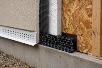
The wall scope brings a fluid-applied or sheet-good WRB and air barrier. The glazing scope brings a sill receptor that may or may not include factory-applied sealant as an air barrier component at its perimeter.
These three systems have different substrates, different application temperatures, different movement accommodation characteristics and different long-term adhesion performance profiles.
Self-adhered rubberized asphalt membranes bond well to clean, primed concrete or masonry curb substrates. They bond poorly to aluminum without a specific primer and they do not accept fluid-applied WRB products as a direct overcoat without compatibility testing.
Fluid-applied air barriers on the wall assembly require a clean, dry substrate and a minimum application temperature that is frequently not met during the roofing scope sequence. Sequencing these two materials to achieve a lapped, continuous connection requires explicit specification language assigning the transition to a specific trade, a specific material and a specific sequence.
Without that language, the default behavior on a fast-track project is for each trade to complete their scope to their scope boundary and move on. The gap that results is not a failure of workmanship.
It is a failure of contract document completeness.
The specification-to-field gap here is severe. Division 07 roofing specifications describe the membrane termination at the curb base.
Division 08 glazing specifications describe the sill receptor installation. Division 07 air barrier specifications describe the WRB application on the wall.
None of the three sections describes the transition between them. In a MasterFormat-organized project manual, the skylight curb transition falls between Section 07 54 00 (thermoplastic membrane roofing), Section 07 27 00 (air barriers) and Section 08 63 00 (metal-framed skylights).
Each section editor writes to their scope. The transition between scopes requires a fourth document, typically a coordination detail issued by the envelope consultant of record, that explicitly assigns materials, substrates, lap dimensions and sequence to a named trade.
Without that document in the contract package, the general contractor has no contractual basis for directing any subcontractor to perform the transition work. A coordination drawing, assigned to the envelope consultant of record and issued as a contract document, is the only reliable mechanism for closing this gap.
A note on the drawing that says “contractor to coordinate” is not a solution. It is documentation of the problem.
Detailing the Transition: What a Buildable Connection Actually Requires
A buildable air barrier transition at the skylight curb-to-wall junction requires four things: a defined material, a defined substrate, a defined lap dimension and a defined sequence. Best practice, not code minimum, calls for a self-adhered transition membrane with a minimum 4-inch lap onto the curb face above the counter-flashing termination and a minimum 4-inch lap onto the wall WRB below the rough opening framing.
The transition membrane must be compatible with both the roofing membrane and the wall WRB; compatibility testing per the membrane manufacturer’s published guidance is required before specification. Products from different manufacturers within the same generic material category, such as two different self-adhered rubberized asphalt membranes, are not automatically compatible as direct overcoat laps.
Adhesion testing on a representative substrate sample, conducted before the specification is finalized, is the only way to confirm that the lapped connection will perform over the service life of the assembly. Several major membrane manufacturers publish compatibility matrices for their products against common WRB and air barrier systems.
Those matrices should be the starting point for the specification, not an afterthought during submittal review.
The curb face substrate must be primed for adhesion. Aluminum upstand faces require a specific primer for self-adhered membrane bonding; skipping that step produces adhesive failure within two to three thermal cycles.
The primer selection must match both the membrane product and the aluminum alloy of the upstand. Anodized aluminum and mill-finish aluminum have different surface energy characteristics and may require different primer formulations.
The primer application requires a clean, solvent-wiped surface and a minimum dwell time before membrane application; that dwell time varies by product and ambient temperature and must appear in the specification as a required hold point, not a general workmanship note. The wall WRB must be applied before the transition membrane is lapped onto it, which means the wall scope must be sufficiently advanced before the transition work begins.
That sequence must appear in the project schedule as a defined dependency, not as an assumption.
At the sill receptor, the end dam-to-curb interface requires a gun-grade sealant that is compatible with both the receptor material and the transition membrane. That sealant joint is part of the air barrier, not just the water management layer.
ASTM C920 Type S Grade NS Class 25 minimum is appropriate for this joint given the differential movement between the receptor and the curb assembly. The sealant must be applied before the transition membrane is lapped over it to create a redundant seal at the most vulnerable point in the assembly.
The end dam itself must be verified as a continuous, unperforated component. Factory-fabricated end dams on aluminum sill receptors are sometimes drilled or notched in the field to accommodate anchor bolt locations or shimming requirements.
Any penetration through the end dam that is not sealed with a compatible sealant before the transition membrane is applied becomes a direct air leakage path through the assembly. That field modification and the required sealant repair, must be addressed in the special inspection scope for the envelope if the project includes envelope special inspections.
If it does not, it must be addressed in the contractor’s quality control checklist for the skylight installation.
The Commission Review Will Find It
Envelope commissioning under NIBS Guideline 3 protocols is becoming a project requirement on institutional and Class A commercial work in most major markets. Blower door testing of the completed building, combined with infrared thermography at the required delta-T, will find an undetailed skylight curb transition.
Every time. The thermal anomaly is too consistent and too linear to miss.
A continuous linear anomaly running the full perimeter of a skylight at the curb-to-wall junction, visible at 15°F delta-T on a calibrated infrared camera, is one of the clearest signatures in building envelope thermography. It does not require interpretation.
It requires a repair estimate and a schedule.
The correction sequence after the building is enclosed is expensive and disruptive in ways that the original detail would not have been. Accessing the curb-to-wall transition from the interior requires removing ceiling grid, cutting back gypsum board and exposing the rough opening framing.
Accessing it from the exterior may require removing counter-flashing and lifting the sill receptor, which means the glazing contractor must be remobilized. The transition membrane application requires the same substrate preparation and sequencing that it would have required during original construction, but now it must be performed in a finished space with active mechanical systems and occupied floors below.
The cost differential between drawing the detail correctly in the contract documents and correcting it after commissioning is not marginal. On a 40-foot perimeter skylight in an occupied institutional building, the correction cost routinely exceeds the original transition detailing cost by a factor of ten or more, before accounting for schedule impact and certificate of occupancy delay.
The question is whether you want the commissioning agent to find it during the review phase, when correction requires cutting open a finished ceiling and resequencing two subcontractors or whether you want to have drawn it correctly in the first place. Get the coordination drawing into the contract documents before the roof goes down.
Assign the transition material and the transition sequence to a specific trade with specific specification language. Then verify it in the field before the wall scope closes the assembly.
The detail is not complicated. The failure to draw it is a choice and it is a choice that consistently produces expensive callbacks, misdiagnosed leaks and commissioning findings that delay certificate of occupancy.
Draw the gap. Own the handoff.