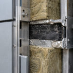
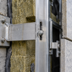
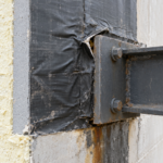
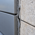
- Premature cladding delamination on a Seattle mid-rise traced directly to a sub-girt system that ignored differential thermal movement.
- Steel Z-girts penetrating continuous insulation can reduce effective R-value by 30 to 40 percent compared to nominal specifications.
- Bracket eccentricity at 6-inch ci thickness makes eccentric moment the governing load case for many commercial configurations.
- NFPA 285 compliance belongs to the full tested assembly and substituting any component can invalidate the entire test result.
- Pre-installation mockups with explicit acceptance criteria are the most reliable mechanism for closing the gap between engineered detail and installed condition.
Rainscreen Attachment Systems: What the Pacific Northwest Teaches Us About Getting It Right
A mid-rise commercial project in Seattle experienced premature cladding delamination within 18 months of occupancy. The forensic investigation traced the failure directly to a sub-girt system installed without accounting for differential thermal movement between the aluminum framing and the concrete substrate.
The remediation cost exceeded the original cladding contract. Litigation followed.
The specification had called for a “rainscreen system per manufacturer recommendations” without a single detail addressing bracket depth, thermal break continuity or movement accommodation at floor lines. That specification language, vague to the point of negligence, is still common in commercial practice today.
The failure was not a material problem. It was an engineering problem.
What Is a Rainscreen Attachment System and Why Does It Matter Now?
The rainscreen principle depends on three interacting mechanisms: a pressure-equalized cavity, a continuous drainage plane and a ventilation gap that allows the cavity to dry after water entry. These three elements must function as a system.
Compromise any one of them and the assembly fails, regardless of how well the other two perform.
First-generation clip-and-rail systems assumed modest insulation thickness, simple substrates and relatively forgiving code requirements. Current integrated sub-girt assemblies operate in a fundamentally different environment.
ASHRAE 90.1-2022 continuous insulation requirements for commercial walls in IECC Climate Zones 4 through 7 now routinely drive ci thicknesses to 3 inches or more. That depth directly affects bracket geometry, load path eccentricity and the distance over which differential movement must be accommodated.
Three performance demands now converge simultaneously on every attachment design: thermal control, structural integrity and moisture management. Code evolution across energy, structural and fire domains has made each of these demands more stringent.
Facade engineers who treat them sequentially rather than concurrently produce assemblies that satisfy one requirement while undermining another. The thermal layer and the structural load path share the same physical space.
There is no designing around that reality.
The Pacific Northwest makes these demands visible in ways that more forgiving climates do not. Marine exposure categories, high annual rainfall totals and significant diurnal temperature swings in Seattle, Portland and Vancouver create conditions that stress every element of the assembly simultaneously.
A bracket system that performs adequately in Phoenix will be tested to its limits in Tacoma. The region functions as a proving ground and the failure patterns that emerge there consistently predict what will appear in other climate zones as energy codes tighten and ci thicknesses increase nationwide.
Practitioners working in IECC Climate Zone 4C and 5 conditions have accumulated field experience with assembly failures that the rest of the country is only beginning to encounter. That experience is worth studying before the failures arrive locally.
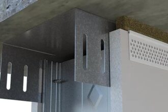
Movement accommodation deserves specific attention as ci thickness increases. A bracket cantilevering 3 inches from a concrete substrate to clear a continuous insulation layer introduces a moment arm that did not exist in earlier shallow-bracket assemblies.
Thermal cycling of the aluminum sub-girt across a Pacific Northwest annual temperature range of roughly 20 degrees Fahrenheit to 90 degrees Fahrenheit generates linear expansion and contraction that must be absorbed at slotted connections. When those slots are omitted, undersized or filled with fastener overtorque, the movement transfers directly to the cladding face.
Delamination, panel cracking and fastener pull-through follow. The Seattle case described above was not an isolated event.
It was a predictable outcome of a specification that ignored the physics.
Thermal Bridging: The Hidden Performance Killer in Sub-Girt Design
Thermal bridging through sub-girt systems is the most consequential and most consistently underestimated variable in rainscreen attachment design. U-value alone does not capture it.
The correct metric is linear transmittance, expressed as a Psi-value (W/m·K), which quantifies the additional heat flow introduced by a repeating thermal bridge relative to the clear-field assembly performance.
The numbers are not subtle. THERM modeling and published data from the Building Envelope Thermal Bridging Guide (BETBR), produced by Morrison Hershfield for BC Hydro, document that a standard steel Z-girt penetrating a continuous insulation layer can reduce the effective R-value of the wall assembly by 30 to 40 percent compared to nominal R-value.
Specify R-20 ci with steel Z-girts at 24 inches on center and you may be delivering an effective R-12 assembly. That gap creates code compliance exposure in jurisdictions that have adopted ASHRAE 90.1-2022 and require effective R-value compliance rather than nominal.
Material conductivity drives this penalty. Carbon steel conducts at approximately 50 W/m·K.
Aluminum conducts at roughly 160 W/m·K, making it worse than steel for thermal bridging despite its lighter weight. Fiberglass-reinforced polymer (FRP) girts conduct at approximately 0.3 W/m·K, three orders of magnitude lower.
Thermally broken aluminum brackets using polyamide thermal breaks fall between 0.5 and 1. 5 W/m·K depending on break geometry and testing methodology.
Bracket spacing, depth and material interact in ways that cannot be resolved by intuition alone. A bracket at 3-inch depth with 24-inch spacing creates a different Psi-value profile than the same bracket at 6-inch depth with 16-inch spacing.
Run the 2D or 3D models. ASHRAE 90.1-2022 Appendix A provides linear transmittance values for common bracket types as a starting point, but site-specific geometry requires site-specific modeling.
Default to THERM or equivalent validated software before finalizing bracket selection.
The condensation risk implications of thermal bridging extend beyond energy code compliance. A steel bracket penetrating ci in a Climate Zone 5 assembly creates a localized cold spot on the interior face of the sheathing.
When interior vapor pressure is sufficient, that cold spot drops below the dew point and condensation forms at the bracket contact point. Repeated condensation cycles promote mold growth on the sheathing face and accelerate corrosion of the bracket base plate if the coating system is inadequate.
Hygrothermal modeling using WUFI or equivalent software should accompany thermal bridging analysis on projects in Climate Zones 5 through 7, particularly where the air barrier and vapor retarder are located on the interior side of the assembly. The thermal bridge and the moisture accumulation risk are not separate problems.
They share a common geometry and must be evaluated together.
Specifying effective R-value rather than nominal R-value in the project documents is the single most direct way to force this analysis into the design process. When the specification requires the contractor to demonstrate effective R-value compliance through tested Psi-values and assembly modeling, the thermal bridging calculation becomes a submittal requirement rather than an afterthought.
Without that language, contractors will submit nominal R-value data for the insulation product alone and the thermal bridge penalty will never appear in the project record.
Structural Loads and Bracket Engineering: Getting the Load Path Right
Structural load resolution precedes thermal optimization in the design sequence. A thermally ideal bracket that cannot carry the load is not a solution.
Brackets must resolve four distinct load types: dead load from cladding self-weight, wind uplift and suction from out-of-plane pressure, seismic in-plane racking and differential movement from both thermal cycling and structural deflection at floor lines. Each load type demands a different engineering check.
Tributary area calculations for bracket spacing must account for cladding weight per square foot, which varies enormously between fiber cement panels at 3 psf and stone cladding at 15 psf or more. Anchor embedment depth into the substrate depends on pullout values that vary by substrate type, not just bracket geometry.
Substrate variability is a genuine field hazard. Concrete and CMU provide reliable pullout values when properly tested and specified.
Steel stud framing requires through-fastening to studs or structural backing plates; anchor pullout into sheathing alone fails. Mass timber substrates present emerging challenges, with published allowable loads still limited compared to concrete and requiring species-specific and grain-direction-specific engineering review.
Manufacturer load tables are a starting point. They are not a substitute for site-specific engineering review.
Tables assume ideal substrate conditions, perpendicular loading and no eccentricity. Field conditions routinely deviate from all three assumptions.
ASCE 7-22 Chapter 30 governs components and cladding wind pressure requirements; facade engineers must confirm whether the project authority having jurisdiction has adopted ASCE 7-22 or remains on ASCE 7-16, because the pressure coefficients differ in ways that affect bracket spacing calculations.
The eccentricity problem deserves more attention than it typically receives in commercial practice. When a bracket cantilevers outward from the substrate face to clear a ci layer, the cladding dead load no longer acts along the bracket’s primary axis.
It acts at the end of a moment arm equal to the bracket depth. At 3-inch ci thickness that moment arm is manageable.
At 6-inch ci thickness, which is increasingly common in Climate Zone 6 and 7 assemblies, the eccentric moment at the anchor becomes the governing load case for many bracket configurations. Manufacturer load tables rarely present eccentric load capacity directly.
They present axial and shear capacities separately and leave the combined loading check to the engineer. Confirm that the structural engineer of record is performing the combined load interaction check, not simply comparing individual load components to tabulated limits.
Floor line deflection creates a related problem that is consistently under-detailed in commercial specifications. Concrete floor slabs deflect under sustained load.
The deflection at mid-span of a typical commercial bay can reach L/360 or more over the building’s service life. Sub-girt systems anchored to the slab edge at each floor line must accommodate that deflection without transferring load to the cladding.
Slotted vertical connections at floor lines are the standard solution, but the slot length must be calculated based on the actual expected deflection, not a generic 1/4-inch default. On long-span concrete structures, the required slot length may exceed what standard bracket products provide.
Verify the calculation before approving the bracket schedule.
Do not let the structural engineer of record sign off on a generic bracket schedule without reviewing the actual cladding weight, bracket geometry and substrate test data. That handoff gap is where structural failures originate.
Material Innovations in Sub-Girt Systems: Beyond Aluminum and Steel
FRP girts offer the most dramatic thermal performance improvement available in current commercial practice. Their effective thermal conductivity near 0.3 W/m·K eliminates the bracket penalty almost entirely in clear-field assembly calculations.
The tradeoff is load capacity. FRP girts carry lower allowable loads than aluminum at equivalent section sizes and exhibit creep under sustained load that must be accounted for in deflection calculations.
They are appropriate for lightweight cladding assemblies and lower wind pressure zones. They are not a universal replacement for aluminum.
Thermally broken aluminum brackets address the load capacity limitation by maintaining aluminum’s structural performance while interrupting the conductive path with a polyamide or structural resin thermal break. The break geometry matters significantly.
A narrow break with high compressive loading compresses over time, reducing thermal performance. Specify brackets with published, third-party tested Psi-values per ISO 10211 and validated thermal performance data per ASTM C1363. Not all manufacturers publish these values.
The absence of third-party tested data is a red flag that should trigger a specification substitution rejection.
Hybrid systems combining stainless steel structural anchors with low-conductivity standoffs offer another path, particularly where point loads are high and bracket depth is constrained. Stainless steel conducts at approximately 15 W/m·K, significantly lower than carbon steel and the point-load geometry limits the thermal bridge footprint compared to a continuous Z-girt.
Carbon fiber composite brackets remain primarily a research and high-performance curtainwall application. The cost premium is not yet justified in standard commercial rainscreen practice, but the structural-to-thermal performance ratio is strong for long-term development.
The specification language surrounding material substitutions in this product category requires particular care. A project specified with thermally broken aluminum brackets at tested Psi-values per ISO 10211 can be value-engineered during bidding to standard aluminum Z-girts if the specification does not explicitly prohibit the substitution and require equivalent tested thermal performance data.
Contractors substituting standard aluminum girts for thermally broken brackets will typically present the substitution as equivalent because both products are aluminum and both carry the required structural loads. The thermal performance difference is not visible in a structural load table.
It only appears in the Psi-value data, which the substitution request will not include unless the specification requires it. Close that gap in the substitution language before the project goes to bid.
Require that any proposed substitution include third-party tested Psi-values demonstrating equivalent or better thermal performance compared to the specified product. Without that requirement, the thermal performance the assembly was designed to achieve will be traded away during procurement without anyone in the approval chain recognizing what was lost.
Cavity Design: Ventilation, Drainage and the Pressure Equalization Principle
The cavity itself is consistently under-detailed in commercial specifications. Bracket selection determines cavity depth and cavity depth determines whether the assembly achieves drained, vented or pressure-equalized performance.
These are not interchangeable terms.
A drained cavity requires a minimum 3/8-inch clear space with drainage mat or open joint at the base. A pressure-equalized cavity requires a minimum 1-inch clear space with controlled ventilation openings sized to the pressure compartment area.
Most commercial rainscreen specifications call for pressure equalization but detail cavities that achieve only drainage. The distinction matters for water management performance in high-exposure conditions, particularly in IECC Climate Zones 5 through 7 and marine exposure categories.
Ventilation opening sizing at the top and bottom of the cavity must relate to the cavity volume and panel area of each pressure compartment. Undersized openings defeat pressure equalization.
Oversized openings in cold climates increase convective heat loss through the cavity and can introduce wind-driven rain at the base.
Air barrier continuity at bracket penetrations is where the four control layers most frequently break down. The thermal control layer and the air control layer occupy the same plane in most ci assemblies.
Every bracket penetration creates a potential air leakage path if the air barrier membrane is not continuously lapped and sealed around the bracket base plate. ASTM E2273 provides the test method for evaluating drainage efficiency in exterior assemblies; specify testing for drainage mat products when used in lieu of an open cavity.
The pressure compartment concept is worth examining in more detail because it is the element most frequently misunderstood in commercial practice. A pressure-equalized rainscreen does not simply have a cavity behind the cladding.
It has a cavity divided into discrete compartments, each of which is sized and vented to equalize the air pressure across the cladding face during a wind event. When the pressure inside the compartment equals the pressure on the exterior face of the cladding, the driving force for water infiltration through panel joints drops to near zero.
That is the performance mechanism. It depends entirely on the compartment being properly bounded, properly sized and properly vented.
Horizontal flashings at floor lines and vertical closures at panel edges define the compartment boundaries. When those closures are omitted or improperly installed, adjacent compartments merge and the pressure equalization geometry is destroyed.
The cavity still drains, but it no longer pressure-equalizes and the water management performance in a high-wind rain event degrades accordingly. In Pacific Northwest exposure conditions, that degradation is not theoretical.
It produces visible water intrusion at panel joints within the first few years of service.
Insect and debris screening at cavity openings introduces a secondary sizing constraint that specifications frequently ignore. A 1-inch cavity opening sized for pressure equalization must also accommodate screening without reducing the net free area below the minimum required for ventilation.
Specify net free area at screened openings, not gross opening dimensions and require the contractor to demonstrate compliance with both the ventilation requirement and the screening requirement simultaneously.
Code Compliance and Testing Requirements Facade Engineers Must Know
Code compliance for rainscreen attachment systems spans at least four distinct regulatory domains and no single code section covers the full assembly. Facade engineers who treat this as a single-code problem produce specifications with gaps.
ASHRAE 90.1-2022 governs thermal performance and requires continuous insulation compliance by effective R-value in prescriptive path calculations. IBC Section 2603.5.5 governs fire propagation testing for foam plastic insulation used as ci behind cladding; assemblies must meet NFPA 285 criteria, which tests the full assembly including the cladding, insulation and air barrier as installed.
A ci product that passes NFPA 285 in one assembly configuration does not automatically pass in a different cladding or air barrier combination.
ASCE 7-22 Chapter 30 governs wind pressure on components and cladding. Seismic requirements for nonstructural components fall under ASCE 7-22 Chapter 13, which requires facade engineers to calculate component importance factors and seismic design categories before finalizing bracket connection design.
Testing requirements for the air barrier layer should reference ASTM E2357 for assembly air leakage and ASTM E1677 for material air leakage. Specify both.
Material compliance alone does not guarantee assembly performance; the bracket penetration details determine whether the tested material performs as intended in the field.
The NFPA 285 compliance gap is worth examining in practical terms because it creates specification errors on a regular basis in commercial practice. A project team selects a mineral wool ci product that has passed NFPA 285 testing in a specific assembly configuration: a particular air barrier product, a particular cladding type and a particular bracket system.
During value engineering, the cladding product changes from fiber cement to a composite metal panel. The mineral wool product is retained because it passed NFPA 285. The problem is that the NFPA 285 test result belongs to the assembly, not to the insulation product in isolation.
Substituting the cladding invalidates the tested assembly configuration. A new NFPA 285 test or a documented engineering analysis demonstrating equivalence is required before the substituted assembly can be considered compliant.
This is not a theoretical concern. Code officials in jurisdictions with active fire code enforcement are increasingly requesting NFPA 285 compliance documentation that matches the as-specified assembly configuration, not just the insulation product data sheet.
Prepare for that request before the permit application, not after.
The interaction between ASCE 7-22 Chapter 13 seismic requirements and bracket design is similarly underappreciated in practice. Nonstructural component seismic design under Chapter 13 requires calculating the component amplification factor (ap) and the component response modification factor (Rp) for the cladding assembly.
For most rainscreen cladding systems, ap equals 1.0 and Rp equals 2. 5 when the system is designed to accommodate seismic displacement without failure.
Achieving that Rp value requires demonstrating that the bracket connections and panel attachment points can accommodate the calculated in-plane displacement without brittle failure. That demonstration requires engineering analysis of the actual bracket geometry and connection detail, not a generic reference to the manufacturer’s seismic compliance claim.
Confirm that the project’s structural engineer of record has performed the Chapter 13 analysis for the specific bracket and cladding combination before the structural drawings are issued for permit.
The specification-to-field gap in rainscreen attachment is not primarily a materials problem. It is a details problem.
Specify bracket type, thermal break requirement, tested Psi-value, minimum cavity depth, air barrier continuity at penetrations and substrate-specific anchor testing as explicit requirements. If your specification says “install per manufacturer recommendations,” you have not specified anything.
You have transferred the engineering responsibility to a sales representative.
The Forward Obligation: Design for the Assembly You Will Actually Build
The most reliable predictor of rainscreen attachment failure is the distance between the engineered detail and the installed condition. Bracket depth changes when ci thickness changes during value engineering.
Cavity depth shrinks when field crews install panels tight to the girt. Air barrier laps get cut short at bracket base plates because no one detailed the transition.
Close that gap before construction begins. Require pre-installation mockups per ASTM E2099 that include the actual bracket, the actual ci product and the actual air barrier membrane as specified.
Inspect the mockup for air barrier continuity at every bracket location before approving the assembly for full installation. If the mockup reveals a detailing problem, you have found it at one panel rather than at 40,000 square feet.
The mockup requirement carries more weight when it is tied to specific acceptance criteria in the specification rather than a general requirement to build and inspect a sample panel. Define what constitutes acceptance.
Require that the air barrier membrane be lapped and sealed continuously around each bracket base plate with no visible gaps or fishmouths. Require that the cavity depth be verified by direct measurement at a minimum of three bracket locations within the mockup area.
Require that drainage mat, if specified, be installed with the drainage direction oriented correctly and the mat cut cleanly around bracket penetrations without compression that would reduce drainage capacity. Require that all panel joints be checked for alignment with the pressure compartment boundaries shown on the drawings.
Each of these criteria corresponds to a failure mode documented in field investigations of rainscreen assemblies that passed a cursory mockup inspection but failed in service. The inspection checklist is not bureaucratic overhead.
It is the mechanism by which the engineered detail gets transferred to the installed condition.
Value engineering pressure on bracket systems deserves direct attention because it is the single most common pathway from a well-engineered specification to a poorly performing assembly. The bracket system typically represents two to four percent of the total facade contract value.
Substituting standard aluminum Z-girts for thermally broken brackets saves a fraction of that already small percentage. The energy performance penalty, the condensation risk and the potential code compliance exposure that result from the substitution carry costs that dwarf the procurement savings.
Document that analysis in writing before the value engineering session and present it to the owner directly. Owners who understand the cost ratio consistently reject the substitution.
Owners who are presented only with a line-item cost comparison frequently approve it. The facade engineer’s obligation is to make the full cost picture visible before the decision is made, not to reconstruct it after the assembly fails.
The bracket systems available today can deliver effective R-values within 10 percent of nominal if specified and installed correctly. That performance is achievable.
It requires engineering the full assembly, not just selecting a product.