EIFS in Commercial Rainscreen Applications: Where the System Performs, Where It Fails and What Modern Hybrid Assemblies Get Right
Why EIFS Is Back in the Conversation: and Why That Makes Some Specifiers Nervous
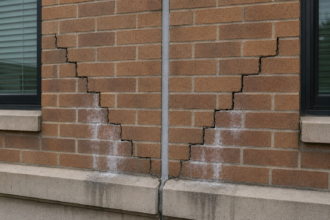
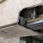
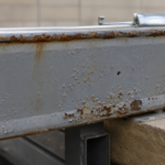
A forensic investigation on a 2006-era four-story medical office building in the Mid-Atlantic region reveals what the inspector expected to find: delaminated base coat at a window head, saturated EPS insulation board and corroded sheathing fasteners behind a barrier-type EIFS assembly that was never designed to drain. The failure is not a material failure.
The lamina performed exactly as specified. It is a detailing failure compounded by a decade of undetected moisture accumulation and this building is one of thousands now aging out of warranty coverage and into litigation exposure.
That context matters because EIFS is simultaneously experiencing a market resurgence and a reputation problem rooted in the wrong decade. ASHRAE 90.1-2022 continuous insulation requirements are making CI mandatory on most commercial assemblies across climate zones and EIFS delivers that CI as an integrated system component at installed costs that remain difficult to match.
EPS-based EIFS routinely achieves effective R-15 to R-20 continuous insulation at price points competitive with metal panel or fiber cement rainscreen assemblies when you account for separate WRB, framing and CI costs on those systems.
The hesitation among specifiers is real. It is also increasingly disconnected from current performance data.
The litigation that defined EIFS’s reputation was concentrated in 1990s residential construction using barrier-type assemblies on wood-frame substrates with no drainage provision. ASTM E2568, the current standard specification for PB Exterior Insulation and Finish Systems and ASTM E2570, the standard test method for water-resistive barrier coatings used in EIFS, now provide a technically rigorous baseline that did not exist during the problem-era installations.
The system has changed. The specification practice has not always kept pace.
What makes the current moment different from the early 2000s recovery period is the convergence of code pressure and cost pressure arriving simultaneously. When ASHRAE 90.1-2019 tightened the continuous insulation requirements for Climate Zone 4 and above, many project teams that had defaulted to metal panel or fiber cement cladding systems suddenly found themselves pricing a separate CI layer, a separate WRB and a separate cladding attachment system on top of the cladding material itself.
EIFS integrates all three functions. That integration is the source of both its cost advantage and its risk profile, because a single applicator crew is responsible for the WRB, the insulation and the finish and a single detailing error affects all three control layers at once.
Specifiers who understand that tradeoff can manage it. Specifiers who are simply relieved to find a system that pencils out on a budget spreadsheet are setting up the next wave of forensic investigations.
Understanding What Actually Failed: Barrier EIFS vs. Drained EIFS vs. Hybrid Rainscreen
The forensic distinction between assembly types is where most specification conversations go wrong, because practitioners often treat “EIFS” as a single system category when it describes three fundamentally different water management strategies.
Barrier EIFS relies entirely on the lamina as the sole water management plane. There is no drainage path.
Any breach at a penetration or termination allows water to accumulate with no exit route and the EPS insulation board is an efficient capillary sponge once it gets wet. This system type is effectively obsolete in commercial specification practice.
If you are still seeing it on project submittals, reject it.
Drained EIFS incorporates a drainage plane at the substrate face, typically a fluid-applied or sheet WRB, with drainage channels or mesh at the EPS-to-substrate interface that allow incidental water to exit at base flashings. This is the current commercial baseline and the minimum acceptable configuration under ASTM E2568 Section 5 drainage requirements and the EIMA Guideline Specification for Drained EIFS.
The drainage mat or channel must be continuous and must terminate at a functional flashing that directs water to the exterior. That last sentence contains the detail that most mid-2000s failures violated.
Hybrid EIFS-rainscreen assemblies add a defined open cavity, typically 3/8 inch to 3/4 inch, between the substrate WRB and the back face of the EPS board. This provides both drainage and back-ventilation.
It is the configuration that most closely mirrors a true pressure-equalized rainscreen wall and is the appropriate specification for high-exposure or high-humidity climate zones, specifically IECC Climate Zones 5 through 7 and any Marine 4C designation.
The forensic pattern in mid-2000s commercial failures is consistent: drained EIFS in name only. The drainage mat was specified.
The base flashing termination was detailed in a way that blocked the drainage exit, converting the assembly back to barrier behavior. The WRB was present.
The drainage function was not. This distinction between a system that is specified as drained and a system that actually drains is the central diagnostic question in any EIFS moisture investigation and it is the question that construction documents from that era consistently failed to answer with enforceable details.
A drainage mat that terminates against a sill flashing leg with no weep opening is a drainage mat that holds water. The mat material itself is irrelevant once the exit path is blocked.
Investigators reviewing project records from that period frequently find that the drainage mat product was correctly specified by manufacturer and thickness and the base flashing was correctly specified by material and gauge and neither detail referenced the other in a way that would have told the installer how the two components were supposed to connect. That coordination gap is a drawing production failure, not a product failure and it is a failure mode that current construction documents still replicate on a regular basis.
Where the System Performs: Climate Zones, Building Types and Assembly Configurations That Favor EIFS
EIFS performs most reliably in IECC Climate Zones 3 through 5 on low-to-mid-rise commercial buildings between two and eight stories, where wind-driven rain exposure is moderate and the substrate is a dimensionally stable sheathing system. Glass mat gypsum sheathing with taped joints is the preferred substrate.
Exterior-grade OSB with taped joints is acceptable with appropriate WRB detailing. Standard gypsum sheathing is not acceptable as a substrate for commercial EIFS regardless of what any submittal claims.
Institutional building types represent the strongest current commercial market for the system. Schools, medical office buildings and government facilities combine budget pressure, CI code requirements and the availability of 10-year system warranties from major manufacturers when installed by certified applicators.
That warranty condition matters: most manufacturer warranties require certified applicator installation and project registration. Specifiers who do not enforce that requirement during bidding routinely find that the warranty is void before the building is occupied.
The system is poorly suited to high-rise applications above eight stories without significant modification to the drainage and ventilation cavity design. Wind pressure differentials at upper floors in high-rise applications exceed the drainage mat’s capacity to manage incidental moisture and the geometry of high-rise fenestration typically generates penetration densities that the system’s detailing library cannot accommodate without custom engineering.
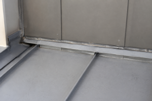
Horizontal surfaces, soffits and below-grade transitions are consistently the highest-risk conditions regardless of climate zone. These locations require either a different cladding material or a fully detailed transition to a waterproofing assembly.
EIFS on a horizontal surface is a liability waiting to be discovered.
The building type and occupancy classification also affect the risk calculus in ways that specifiers should make explicit in their project documentation. A K-12 school in Climate Zone 4 with a 30-year design life and a facilities staff that will conduct annual inspections is a different risk profile than a speculative medical office building in the same climate zone that will change ownership twice before the 10-year warranty expires.
The system’s performance over time depends on the quality of the initial installation and on the building owner’s willingness to maintain sealant joints at penetrations and transitions. Silicone sealant at EIFS terminations has a realistic service life of 10 to 15 years under normal UV and thermal cycling exposure.
A building owner who does not know that the sealant joints require periodic inspection and replacement is a building owner who will be surprised by the moisture investigation report 20 years from now. That information belongs in the project closeout documentation and it belongs in the specification as a maintenance requirement, not as a footnote in the manufacturer’s product data sheet.
Where It Fails: The Five Detailing Errors That Generate 80% of EIFS Moisture Claims
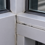
Fenestration head flashing integration is the single most common failure point. EIFS base coat and mesh are terminated directly against window flanges or receptor frames without a through-wall flashing that directs water out of the drainage plane.
Water that enters at the sealant joint has no exit path and migrates laterally behind the EPS. The fix is not complicated: a sloped metal flashing at the window head, lapped over the WRB below and terminated at the exterior face of the EPS with a drip edge.
The detail exists in every manufacturer’s technical manual. It is omitted on a significant percentage of installed projects.
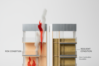
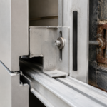
Floor-line fire barrier interruption is the second major failure mode and the one most likely to generate code exposure in addition to moisture claims. IBC Section 1402.5 and NFPA 285 require fire-resistant thermal barriers at each floor line in EIFS assemblies on buildings over 40 feet.
The steel angle or mineral wool fire barrier detail at the floor line is also the most common location for drainage plane discontinuity. The base flashing termination above the angle is frequently omitted or improperly lapped, which breaks the drainage continuity at exactly the location where the assembly is most vulnerable to water accumulation.
Transition to dissimilar cladding materials is routinely underdetailed. EIFS-to-metal panel, EIFS-to-masonry and EIFS-to-storefront transitions require a defined sealant joint with a backer rod and a WRB lap that directs water to the exterior.
These transitions appear on construction documents as a simple sealant line with no WRB integration detail. The sealant fails.
The WRB is not there to catch it.
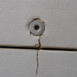
Base termination above grade is a code and manufacturer requirement that field crews routinely ignore. Most manufacturer specifications and EIMA guidelines require a minimum 8-inch termination above finished grade.
Terminations closer to grade allow capillary moisture uptake into the EPS. This failure mode is visible on virtually every project where grade has been regraded after installation.
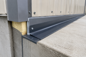
The fifth failure mode is parapet and roof-to-wall transition detailing. EIFS that continues up and over a parapet without transitioning to a waterproofing assembly at the top of the parapet is a moisture pathway that bypasses every drainage feature in the wall assembly below.
The parapet cap must be a separate waterproofing assembly. The EIFS must terminate below the cap with a metal counterflashing.
This is not optional and it is not a best practice recommendation; it is the only configuration that provides all four control layers: water, air, vapor and thermal continuity at the roof-to-wall interface.
What connects all five failure modes is a common mechanism: the detail that exists on the drawing does not translate into a field condition that performs the intended function. The fenestration head flashing is shown on the drawing but the drip edge is omitted in the field.
The floor-line flashing is shown on the drawing but the installer laps it in the wrong direction. The base termination height is specified in the written specification but is not called out on the elevation drawings where the installer is actually working.
Forensic investigators who review construction photographs from failed projects frequently find that the details were present in the contract documents and absent in the field, which means the failure is a construction administration failure as much as it is a design failure. Envelope consultants who conduct periodic site observations during EIFS installation, specifically at the completion of WRB installation, at the completion of EPS board installation and at the completion of base coat application, catch the majority of these errors before they are buried behind finish coat.
Envelope consultants who review submittals and then disappear until substantial completion do not.
The Hybrid Rainscreen Configuration: What It Gets Right and What It Costs
The hybrid EIFS-rainscreen assembly with a defined open cavity solves the drainage problem that drained EIFS only partially addresses. By separating the EPS board from the substrate WRB with a continuous 3/8-inch to 3/4-inch air space, the assembly creates a genuine drainage and drying path rather than relying on a drainage mat that can compress, clog or terminate incorrectly.
The air space also changes the hygrothermal behavior of the assembly in ways that matter for vapor control. In Climate Zones 4 through 6, the drained cavity keeps the WRB surface temperature above the dew point for a significantly longer portion of the heating season than a direct-applied assembly, reducing the condensation risk at the sheathing face.
This is not a vapor barrier question. Air leakage transports orders of magnitude more moisture than vapor diffusion and the hybrid configuration addresses air leakage at the WRB plane while providing a secondary drainage path for any water that gets past the lamina.
The cost premium for the hybrid configuration over standard drained EIFS is typically 15 to 25 percent of the EIFS assembly cost, which translates to roughly $3 to $6 per square foot depending on the cavity depth and the attachment system. That premium is worth quantifying explicitly in the specification so that value engineering conversations happen before the detail is stripped out, not after.
The attachment system for the hybrid configuration requires more careful engineering than standard drained EIFS because the EPS board is not bearing directly against the substrate. Proprietary clip-and-rail systems from manufacturers including Dryvit, Parex and STO provide tested attachment solutions with defined load paths for wind uplift and seismic racking.
These systems have specific fastener schedules based on wind zone and substrate type and those schedules must be incorporated into the structural drawings, not left to the applicator’s field judgment. The clip spacing also determines the effective cavity depth and cavity depth affects both the drainage capacity and the thermal performance of the assembly.
A 3/8-inch cavity provides adequate drainage in moderate exposure conditions. A 3/4-inch cavity is appropriate for high-exposure coastal or high-rise applications where wind-driven rain loads are higher and drying time between rain events is shorter.
Specifying the cavity depth as a performance requirement rather than a prescriptive dimension gives the applicator flexibility to use their manufacturer’s proprietary system while ensuring the assembly delivers the drainage and drying capacity the design requires. That approach also makes the specification defensible if the applicator substitutes a different attachment product during construction, because the performance requirement gives the design team a basis for evaluating the substitution rather than simply accepting or rejecting it on the basis of product name.
Specifying It Correctly: The Minimum Technical Framework
A defensible EIFS specification for commercial work in 2024 requires six non-negotiable elements. The assembly must be a drained system meeting ASTM E2568 with drainage documentation.
The WRB must be tested under ASTM E2570 and must be a product the EIFS manufacturer has specifically qualified for use with their system. All fenestration head flashings must be detailed as through-wall metal flashings with drip edges, not sealant terminations.
The floor-line fire barrier detail must show continuous drainage above and below the angle with explicit flashing laps. All cladding transitions must show WRB integration with a minimum 6-inch lap to the exterior.
And the applicator must be manufacturer-certified with a registered project number before the first bag of base coat is mixed.
That last requirement is the one most frequently omitted from bid documents. Without it, the warranty is void and the specification is unenforceable.
The specification should also address mock-up requirements with enough specificity to make the mock-up useful as a construction quality benchmark rather than a contractual formality. A 4-foot by 8-foot flat panel mock-up that shows only the base coat and finish coat application tells you nothing about the detailing conditions that generate moisture failures.
The mock-up should include at minimum one window head condition, one base termination condition and one floor-line fire barrier condition. It should be reviewed and approved by the envelope consultant before any field installation proceeds and it should remain on site as a reference standard through the completion of EIFS work.
Specifiers who require mock-ups but do not define their content in the specification get mock-ups that show the applicator’s best finish coat work and nothing else. The mock-up requirement in CSI MasterFormat Section 07 24 00 should reference the specific conditions to be demonstrated, not simply require a mock-up panel of a defined size.
What the Next Wave of Failures Will Look Like
The mid-2000s EIFS failures were barrier-system failures. The failures that forensic investigators will be documenting in 2030 will be drained-system failures at floor-line transitions and fenestration heads, because those are the details that current construction documents still get wrong at the highest rate.
The system is not the problem. The specification-to-field gap at transitions is the problem and it will not close until envelope consultants stop treating EIFS transition details as something the manufacturer’s standard detail library can handle without project-specific engineering.
If you are specifying EIFS on a building with more than eight fenestration openings per floor, more than two cladding material transitions or a floor-line fire barrier requirement, hire a building envelope consultant to produce project-specific transition details before the drawings go to bid. The cost of that engagement is measurable in days.
The cost of the forensic investigation it prevents is measurable in years.
The buildings going up right now in Climate Zones 4 and 5 with drained EIFS and floor-line fire barriers are the