- Composite metal soffit assemblies routinely fail when specifiers apply vertical rainscreen drainage logic to horizontal surfaces.
- Condensation accumulates at aluminum subframe interfaces because standard cavity slopes and weep slot placements are functionally useless on near-horizontal planes.
- Steel substrates and fasteners can lose significant structural capacity within five to eight years due to undetected moisture cycling in soffit cavities.
- Standard facade inspection protocols and infrared thermography frequently miss internal substrate corrosion until visible failure has already occurred.
- Geometry-specific details including minimum 2% slope, 1.5-inch cavity depth and correctly placed weep slots can prevent the failure pattern now appearing across projects built between 2015 and 2022.
Composite Metal Soffit and Canopy Assemblies: Why Horizontal Surface Drainage Details Keep Failing and What Geometry-Specific Design Actually Requires
A transit hub canopy in the mid-Atlantic region, completed less than four years prior, presented with widespread substrate corrosion and panel delamination during a routine warranty inspection. The source was not roof leaks above.
Condensation had been accumulating at the aluminum subframe interface beneath a composite metal soffit assembly detailed using standard vertical rainscreen logic. The drainage slots were oriented for gravity flow on a vertical plane; on a 2% slope, they were functionally useless.
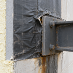
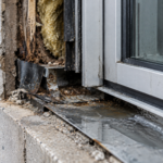
The failure was invisible from grade until framing members began to show rust bleed at panel joints. By the time the warranty inspector flagged it, the steel substrate had corroded through in three locations and two hat channel anchors had lost more than 40% of their section.
Nobody caught it because nobody designed a drainage path that worked in that geometry and nobody inspected the cavity because the standard protocols do not require it.
Soffits and Canopies Are Not Vertical Facades in Disguise
The geometry problem is straightforward and routinely ignored. Soffits and canopies operate on horizontal or near-horizontal planes, typically between 0 and 15 degrees from horizontal, where every gravity drainage assumption embedded in vertical rainscreen design simply does not apply.
Water does not run down. It runs sideways, pools, wicks and stagnates.
Detailing these assemblies as if they were rotated walls produces predictable failures.
Three primary assembly types appear in commercial practice: composite metal panel soffits (ACM or MCM panels on a subframe), open-joint metal plank soffits with exposed framing and canopy cap assemblies with integrated fascia returns. Each has distinct drainage requirements.
Each is frequently specified using the same panel manufacturer’s standard vertical facade detail, reformatted for a horizontal application without geometry-specific modification. That substitution is the root cause of most failures I investigate in this category.
The reformatting is often performed by a drafter, not the specifier of record and it receives no independent technical review before it enters the construction document set.
The project types where this concentrates are mixed-use podium entries, transit canopies, institutional covered walkways and parking structure soffits. These are high-exposure, high-dwell-time environments where moisture loading is significant and inspection access after installation is limited.
Parking structure soffits are particularly problematic because they combine chloride exposure from road salt migration with the condensation mechanism described below, accelerating steel corrosion at a rate that can compromise structural framing within five to eight years of installation. ASTM E2128, the standard guide for evaluating water leakage of building walls, is explicitly wall-centric in scope.
There is no horizontal assembly equivalent. That gap in the standards library is not an accident; it reflects how little systematic attention this assembly category has received.
Until a horizontal-specific standard is developed and adopted, the design team bears the full burden of translating vertical assembly logic into geometry-appropriate practice without a codified reference to support that translation.
How Vertical Rainscreen Logic Fails When Rotated 90 Degrees
The pressure-equalized rainscreen principle works on vertical surfaces because it combines three mechanisms: a capillary break at the panel-to-framing interface, a drained cavity that moves water downward by gravity and a vented exterior plane that equalizes pressure across the panel. All three depend on downward gravity flow.
Rotate the assembly 90 degrees and the third mechanism disappears entirely, the second becomes a pooling zone and the first becomes a water trap.
The specific failure modes are worth naming precisely. Drainage slots at panel edges, designed to allow water to exit a vertical cavity, become water entry points on a horizontal soffit when wind-driven rain or condensate migrates toward them.
Cavity air circulation stagnates because the convective stack effect that drives air movement in vertical cavities does not operate horizontally. Condensate pools at low points rather than draining to designed weep locations, because the weep locations were placed using vertical facade logic.
In one institutional covered walkway project I reviewed post-failure, the panel installer had faithfully reproduced the manufacturer’s vertical detail, including side-edge drainage slots at 24-inch spacing. On the horizontal soffit, those slots collected and held water against the panel bond line.
Panel delamination was documented at 14 of 22 bays within six years of substantial completion.
The slope threshold problem compounds this. Industry soffit details frequently specify 1/8 inch per foot, approximately 1%, as the drainage slope.
SMACNA’s Architectural Sheet Metal Manual, 7th Edition, specifies 1/4 inch per foot as the minimum for positive drainage on horizontal metal surfaces. The 1/8 inch figure is insufficient to overcome surface tension in narrow panel cavities and it is routinely lost to construction tolerance during installation.
A framing crew working to plus or minus 1/4 inch in elevation across a 20-foot canopy run can easily produce a flat or reverse-sloped cavity with no drainage at all. When the specified slope is already at the margin of constructability, any tolerance stack in the wrong direction eliminates drainage entirely.
Specifying 1/8 inch per foot on a horizontal soffit is effectively specifying no drainage.
The air gap dimension compounds the problem further. Vertical rainscreen cavities of 3/4 inch to 1 inch function adequately on walls because air movement carries moisture out.
The same cavity dimension on a horizontal soffit traps humid air and creates a condensation microclimate at the substrate face. ASHRAE 160-2021 addresses dew point proximity at horizontal substrate interfaces in mixed-humid and cold climates; the dew point risk at an aluminum subframe in IECC Climate Zones 4 through 6 during winter months is not theoretical.
It is predictable from first principles and it is being ignored in standard practice. A designer who runs a basic dew point calculation using ASHRAE 160 methodology for a Zone 5 location will find that an uninsulated aluminum subframe in direct contact with a steel substrate will fall below the dew point of interior-adjacent cavity air for a significant portion of the heating season.
That calculation takes approximately 20 minutes. It is not being performed on most soffit projects.
The Condensation Mechanism at the Substrate Interface
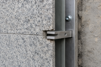
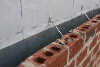
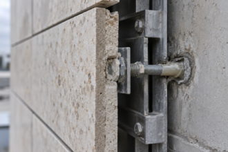
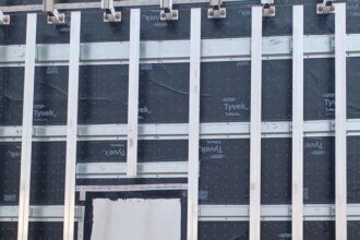
The thermal bridging pathway in canopy and soffit assemblies differs from vertical facades in one specific way that makes it more damaging. Metal subframe members, typically aluminum hat channels or Z-girts, conduct exterior cold temperatures directly to the substrate face without the benefit of a continuous insulation layer between the cladding and the substrate.
On a vertical facade with proper CI placement, the subframe sits outboard of the insulation and the substrate stays warm. On most soffit assemblies, the subframe is embedded within or directly against the substrate, creating a localized cold surface inside the cavity where condensation forms preferentially.
The accumulation sequence is direct. Warm interior-adjacent air migrates into the soffit cavity through panel joints and penetrations.
It contacts the cold subframe and substrate face. Condensate forms on the substrate.
No drainage slope or weep path exists to remove it. Moisture cycles repeat daily through seasonal transitions.
The result is accelerated corrosion of steel substrate, fasteners and framing, degradation of any gypsum sheathing used as a substrate backer in enclosed canopy assemblies and rot at untreated wood blocking at panel terminations. The fastener corrosion component deserves specific attention: self-drilling screws used to attach hat channels to steel substrate are typically zinc-coated carbon steel.
In a sustained condensation environment, those fasteners lose protective coating within two to three years and begin losing section within four to six. By year seven or eight, fastener pullout capacity can be reduced by 30 to 50% from design values, which is the condition that produces the anchor failures described in the transit hub case at the opening of this article.
Steel deck, gypsum sheathing and untreated wood blocking are the three substrate materials most vulnerable to this failure mode. Each appears frequently in canopy assemblies.
None tolerates sustained moisture cycling without significant performance degradation. Type X gypsum sheathing, which is commonly used as a substrate backer in enclosed canopy assemblies for fire resistance continuity, begins to lose structural integrity at the fastener interface when moisture content exceeds approximately 1% by weight.
That threshold is reached quickly in a stagnant condensation environment. Once the sheathing degrades at the fastener location, the panel attachment system loses its load path and the assembly becomes a life-safety concern, not just a warranty issue.
The detection lag is the most operationally damaging aspect of this failure mechanism. Because soffit assemblies are overhead and enclosed, visual inspection from grade cannot identify substrate corrosion until panel fasteners begin to fail or rust staining appears at joints.
In humid climates, IECC Climate Zones 3A and 4A specifically, that lag is typically 3 to 7 years post-installation. By the time the failure is visible, the substrate damage is extensive.
A project that shows its first rust bleed at panel joints in year four likely has substrate corrosion that began in year one or two. The visible symptom is a lagging indicator, not a leading one.
IBC 2021 Section 1403.2 requires that exterior wall coverings protect the structural members of the building from moisture. Current soffit detailing practice is not meeting that intent.
What Standard Facade Inspection Protocols Miss
Standard facade inspection methodology applied to soffit assemblies consists of visual survey from grade or lift, sealant joint assessment and panel face examination. None of these methods access the cavity or the substrate interface.
They document what is visible from outside. The failure mode in horizontal soffit assemblies is entirely internal.
A facade inspector following ASCE 7 facade inspection guidelines or a local facade safety program protocol will complete a soffit survey, note no visible deficiencies and move on. The report will reflect the assembly as performing adequately.
The substrate behind it may be actively corroding at the time that report is written.
Infrared thermography, the most common non-destructive diagnostic tool in facade investigation, produces unreliable results on horizontal soffit assemblies. Solar loading on the panel exterior and the thermal mass of the assembly suppress the temperature differential signatures that indicate moisture presence.
On a vertical facade, IR thermography can reliably locate wet insulation or substrate saturation. On a horizontal soffit, the same technique frequently produces a clean thermal image over a corroding substrate.
I have confirmed this directly in post-failure investigations where IR surveys conducted six months before visible failure showed no anomalies. The physical reason is straightforward: solar gain on the panel exterior heats the assembly from outside, masking the cooler signature that wet substrate would otherwise produce.
Evening IR surveys, conducted after solar loading has dissipated, produce more reliable results on horizontal assemblies, but they require deliberate scheduling and are not standard practice in facade inspection programs.
The warranty coverage gap reinforces the problem. Most composite metal panel manufacturer warranties cover panel delamination and finish degradation but explicitly exclude damage resulting from improper drainage design or condensation.
This exclusion is standard language across the MCM product category. It places liability squarely on the specifier and contractor, not the product.
The project team that applied vertical facade details to a horizontal assembly owns the failure. Reviewing the warranty exclusion language from three major MCM manufacturers confirms that condensation damage, water infiltration resulting from inadequate slope and damage from standing water in the panel cavity are all explicitly excluded.
The manufacturer’s standard detail, which the specifier used as the basis for the construction documents, does not produce an assembly that the manufacturer will warrant in a horizontal application. That disconnect is not disclosed at the point of specification.
ASTM E1186 covers air leakage site detection in building envelopes and is applicable to cavity investigation, but it is not routinely specified for soffit assemblies. ASTM E2128 does not address horizontal assemblies.
The standards gap is real and it is not being compensated for by field practice. A specifier who wants to establish a defensible inspection protocol for a horizontal soffit assembly must currently assemble one from vertical-assembly standards, manufacturer technical bulletins and project-specific engineering judgment.
That is a reasonable expectation for a licensed design professional, but it requires acknowledging that the standard details are insufficient, which most project teams are not doing.
Geometry-Specific Drainage Details That Actually Work
The minimum slope standard for functional drainage in horizontal metal panel cavities is 1/4 inch per foot, which is 2%, as a design minimum. Three-eighths inch per foot is preferred where framing geometry allows it.
This is not a conservative recommendation; it is the SMACNA minimum for horizontal metal surfaces and it accounts for the construction tolerance reality that specified slopes are routinely reduced by 30 to 50% in the field. Design to 3/8 inch per foot and you have a reasonable probability of achieving 1/4 inch per foot as-built.
The slope must be built into the subframe, not assumed from the structural deck. Structural concrete decks and steel framing are designed to structural tolerances, not drainage tolerances.
A soffit subframe that relies on the structural deck slope to achieve panel cavity drainage will fail to achieve that slope in most field conditions.
Weep slot placement must be designed for the actual drainage direction, not adapted from a vertical facade detail. On a horizontal soffit with slope running toward the building perimeter, weep slots belong at the low edge of each panel bay, sized to overcome surface tension.
A slot width of 3/16 inch minimum is the functional threshold; narrower slots wick and retain water rather than draining it. Slots should be positioned at the downslope panel edge, not at panel sides where they serve no drainage function in a horizontal application.
The slot should be located at the panel-to-subframe interface, not at the panel face, so that water exiting the cavity clears the subframe before it reaches the panel edge. A slot at the panel face in a horizontal application creates a visible water streak on the panel exterior and does not drain the cavity effectively.
The detail distinction is small on paper and significant in performance.
The cavity air gap requires a minimum of 1-1/2 inches on horizontal assemblies to allow meaningful air circulation. The 3/4 inch cavity standard from vertical rainscreen practice is insufficient.
Increasing the cavity depth increases the effective R-value of the air space and reduces the dew point risk at the substrate face by keeping the substrate surface temperature above the dew point of cavity air during typical service conditions. The increased cavity depth does require a corresponding adjustment to the subframe attachment geometry.
Hat channels or Z-girts sized for a 3/4 inch vertical cavity will not produce a 1-1/2 inch horizontal cavity without modification. This is a coordination item between the panel system design and the structural attachment design that must be resolved in the construction documents, not in the field.
Continuous insulation placement between the subframe and the substrate is the correct thermal control layer strategy for enclosed canopy assemblies. A minimum of R-7.5 ci, using faced polyisocyanurate meeting ASTM C1289, placed outboard of the substrate and inboard of the subframe, keeps the substrate face above dew point in IECC Climate Zones 4 through 6 under most design conditions.
The faced polyisocyanurate specification matters: unfaced polyiso in a horizontal cavity application can absorb moisture at the exposed foam surface, degrading thermal performance over time. The foil facing provides a vapor retarder at the insulation surface and maintains R-value stability in the cavity environment.
This is not a code requirement in most jurisdictions; it is a best practice recommendation based on the condensation mechanism described above. The distinction matters: IBC 2021 Section 1403.2 establishes the performance intent but does not prescribe this specific assembly configuration.
A jurisdiction that enforces Section 1403.2 strictly could require it; most do not, which means the design team must choose to include it based on performance reasoning rather than code compliance pressure.
The Specification-to-Field Transfer Problem
Even when a project team produces geometry-specific soffit drainage details, the transfer to field execution fails at predictable points. Slope is the first casualty.
Framing contractors working from standard horizontal layout drawings do not automatically build drainage slope into soffit framing unless the construction documents call it out explicitly in section and specify it as a verified condition in the special inspection program. A slope requirement buried in a specification section does not get enforced at the framing inspection.
The framing inspector verifies member size, spacing and connection, not cavity slope. If the slope is not on the inspection checklist with a specific tolerance and a verification method, it will not be checked.
The inspector is not being negligent; they are working to the scope they were given.
Weep slot orientation is the second failure point. Panel installers working from vertical facade experience will orient drainage slots the way they always have.
Without a detail that explicitly shows the horizontal assembly condition and the correct slot position, the default is the familiar vertical detail. This is not negligence; it is pattern recognition under production pressure.
A panel installer who has installed the same MCM product on 15 vertical facade projects in the past three years will execute the soffit installation using the same muscle memory unless the construction documents make the geometry-specific requirements impossible to miss. A note in the specification that says “drainage slots shall be oriented for horizontal drainage” is not sufficient.
A detail that shows exactly where the slot goes, at what dimension and at what location relative to the subframe, is the minimum communication standard that produces correct field execution.
The practical fix is to produce a soffit-specific detail set that is completely independent of the vertical facade details, even when the same panel product is used on both surfaces. Reference the soffit details explicitly in the Division 07 specification section for the panel system and require the installer to confirm in writing that they have reviewed the geometry-specific requirements.
Include soffit cavity drainage slope in the special inspection checklist with a tolerance of plus 1/8 inch per foot and zero minus, meaning the slope can exceed the design minimum but cannot fall below it. Require the framing contractor to submit as-built slope measurements at each bay before panel installation begins.
These are not extraordinary measures. They are the minimum coordination steps that the current failure rate in this assembly category demonstrates are not happening.
The submittal requirement for as-built slope measurements is particularly effective because it forces the framing contractor to own the slope verification before the panels go up, rather than discovering the problem during a post-installation investigation years later.
What the Next Warranty Cycle Will Reveal
The transit hub failure described at the opening of this article is not an isolated case. It is an early data point in a failure category that will become significantly more visible over the next five to ten years as mixed-use and transit-oriented projects completed between 2015 and 2022 reach the age at which concealed substrate corrosion produces visible symptoms.
The assemblies are in the ground. The details were wrong.
The inspections missed the damage. The warranty language excludes the failure mode.
The projects are now in the ownership phase, where the original design team has no ongoing involvement and the building owner has no technical basis for identifying the problem before it becomes a safety issue.
Specifiers who are currently detailing horizontal soffit assemblies have a narrow window to break the pattern before their projects join that cohort. The geometry-specific drainage requirements are not complex; they require slope, weep slot placement logic and cavity depth standards that differ from vertical facade practice.
The failure to apply them is not a technical knowledge gap. It is a workflow gap: the soffit detail is being treated as a minor adaptation of the facade detail rather than as a separate design problem.
The workflow fix is administrative as much as it is technical. It requires a project checklist item that flags any horizontal or near-horizontal panel application for geometry-specific detail review before the construction documents are issued.
That checklist item does not exist in most firms. Creating it costs nothing.
The substrate corrosion you prevent will never appear in a warranty claim, which means you will never get credit for it. Do it anyway.