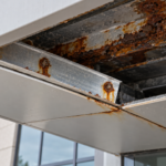
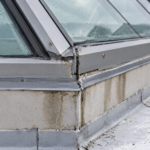
- Barrier EIFS over CMU traps construction moisture with no outward drying path, creating a well-documented failure mode in Climate Zones 5 through 8.
- Mineral wool CI board’s vapor permeability allows CMU assemblies to dry outward, reducing chronic moisture accumulation risk over multiple heating seasons.
- EPS foam in EIFS triggers NFPA 285 compliance requirements for Type I and II construction while noncombustible mineral wool sidesteps that entire liability chain.
- Thermal bridging through mechanical attachment reduces mineral wool’s effective R-value below nominal and must be calculated at the specification stage.
- Pre-installation mockups and enforced shelf angle detailing are the most effective controls separating long-term performers from costly callbacks.
EIFS vs. Mineral Wool CI Board Over CMU: Moisture, Fire and Code Compliance in Mid-Rise Facades
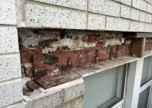
A facility manager’s call six months after occupancy is never good news. On a mid-rise mixed-use project in the Mid-Atlantic, the report was efflorescence at window heads and soft spots in the EIFS field on the third floor.
The forensic investigation was not complicated: the CMU backup wall had been enclosed during a wet autumn schedule before the masonry had dried and the EIFS lamina had sealed that construction moisture in with nowhere to go. No drainage plane.
No vapor-open path outward. Just trapped water working its way through the assembly until the evidence became impossible to ignore.
This scenario repeats across dozens of projects every year. The EIFS-versus-mineral-wool-ci-board decision is not a line-item substitution.
It is a choice between two fundamentally different moisture and risk philosophies and on CMU substrates in mid-rise Type I and II construction, that choice carries fire code exposure that most project teams are not fully pricing into their analysis.
Why the CMU Substrate Changes Everything
CMU behaves differently than steel stud or wood framing under exterior insulation and specifiers who treat it as interchangeable with light-frame substrates create problems that show up years later. CMU is a high-mass, high-moisture-storage material.
It absorbs and releases moisture slowly. New CMU walls carry significant construction moisture from mix water, grout and mortar and that moisture needs a drying path.
EIFS creates a vapor-closed exterior face. Mineral wool is vapor-open.
That single difference drives most of the performance divergence between the two systems.
The thermal mass of CMU also shifts dew point location seasonally in ways that light-frame assemblies do not. In Climate Zones 4 and above per IECC, the insulation layer’s vapor permeability directly affects whether condensation accumulates at the CMU face over a heating season.
ASHRAE 160-2021 provides the hygrothermal design thresholds for mass wall assemblies and any serious moisture analysis for these projects should be running against those criteria, not relying on prescriptive rules of thumb developed for frame construction.
CMU’s surface irregularity also matters practically. Adhesive EIFS attachment over an irregular CMU face produces inconsistent bond area.
Mechanical fastening used in ci board assemblies tolerates surface variation far better and produces more predictable pull-out resistance.
What makes this substrate particularly unforgiving is the combination of high initial moisture content and slow drying rate. A 12-inch grouted CMU wall constructed in September in Philadelphia or Baltimore can carry moisture content well above equilibrium through the following spring.
If that wall is enclosed behind a vapor-retarding exterior insulation system before the heating season begins, the inward drying path through the interior finish system becomes the only available route. Interior gypsum board with latex paint runs at roughly 3 to 5 perms, which is not sufficient to drive meaningful drying rates through a mass wall assembly under winter conditions.
The moisture stays in the wall. It migrates to the CMU face under vapor pressure differentials and over multiple heating seasons it accumulates rather than dissipates.
Specifiers who have worked primarily with light-frame steel stud construction often underestimate this dynamic because steel stud assemblies carry far less initial construction moisture and dry much faster. The CMU substrate demands a different set of assumptions from the first line of the wall assembly specification.
How EIFS Manages and Mismanages Moisture Over CMU
Barrier EIFS, both Class PB and Class PM per ASTM E2568, relies on the lamina as the primary water control layer. Any breach in that lamina, whether from cracked mesh, failed sealant at penetrations or improper terminations, routes water directly to the CMU face with no drainage path out.
On a substrate that holds moisture as tenaciously as CMU, that failure mode is not recoverable without remediation.
Drainage-plane EIFS addresses this by introducing a defined drainage cavity or drainage mat behind the insulation board. The logic is sound.
The execution is the problem. Drainage EIFS adds cost and detailing complexity and it is the first thing that disappears under value-engineering pressure.
When the drainage function is removed but the vapor-closed EPS layer remains, the assembly performs worse than a simple barrier system because the team believes they have addressed moisture risk when they have not.
EPS insulation board in most EIFS assemblies carries a perm rating of approximately 1 to 2 perms at 1-inch thickness. That rating effectively vapor-retards the assembly and limits inward drying from the CMU.
In Climate Zones 4 and above, this creates chronic moisture accumulation risk over multiple heating seasons. The EIFS Industry Members Association Guideline Specifications require drainage EIFS on all CMU substrates in Climate Zones 5 through 8 and explicitly discourage barrier EIFS over CMU in those zones.
That guidance exists because the failure mode is well-documented. Specifying barrier EIFS over CMU in a Zone 5 project is not a gray area.
Proper EIFS over CMU demands a continuous air barrier at the CMU face, correctly lapped WRB and fully back-wrapped terminations at all fenestration openings. These details are routinely missed under schedule pressure.
Air leakage transports orders of magnitude more moisture than vapor diffusion, which means an incomplete air barrier at the CMU face is a far greater risk than the vapor permeability of the EPS layer alone.
The sealant joint at window heads deserves particular attention because it is where barrier EIFS failures concentrate on CMU construction. Sealant over CMU requires a properly prepared substrate, correct backer rod sizing and a sealant product compatible with both the EIFS lamina and the CMU face.
On fast-track projects, window installation and EIFS application frequently overlap trades and the sequencing required to achieve a properly lapped and sealed termination at the window head is compressed or skipped entirely. The result is a direct water entry path at the most vulnerable location in the assembly, directly above the window opening where water concentrates from the field above.
When that water enters behind the EPS layer and contacts the CMU face, it has no exit. The efflorescence and soft spots that prompted the facility manager’s call in the opening example of this article are the predictable outcome of that sequence of decisions.
How Mineral Wool CI Board Manages Moisture Over CMU
Mineral wool ci board, whether stone wool or slag wool, is vapor-permeable at typically 15 to 30 perms depending on density and thickness. That permeability allows the CMU assembly to dry outward, which is the fundamental performance advantage in high-humidity and cold climates.
Construction moisture in new CMU has a path out. Seasonal condensation at the CMU face has a path out.
The assembly is not a closed system.
The open-fiber structure does not trap liquid water. Bulk water that penetrates the cladding attachment zone drains through the insulation layer rather than pooling at the CMU face.
This is not the same as a drained cavity; the mineral wool itself is not performing drainage in the way a defined gap does. The system still requires a separate, defined WRB at the CMU face, either fluid-applied or sheet membrane and a properly designed drainage plane behind the cladding.
The insulation is not the water control layer. Separating those functional roles clearly is what makes this assembly perform reliably over time.
ASTM C1104 measures moisture absorption in mineral wool products and leading manufacturers publish water absorption values below 1 kg per square meter under that standard. ASTM C1338 confirms fungal resistance.
Hygrothermal modeling studies from Building Science Corporation on vapor-open ci assemblies over mass walls consistently show lower moisture accumulation at the CMU face compared to vapor-retarding assemblies, particularly through the first two to three years when construction moisture is still dissipating.
Mineral wool’s dimensional stability also means long-term thermal performance does not degrade the way EPS can when repeatedly wetted and dried.
The WRB selection behind mineral wool ci board on CMU deserves more attention than it typically receives in specifications. Fluid-applied membranes applied directly to the CMU face provide the most reliable continuity over an irregular substrate, bridging the surface voids and texture variation that sheet membranes can bridge inconsistently.
Products meeting ASTM D1970 for self-adhering sheet membranes or ICC-ES AC38 for fluid-applied WRBs are both acceptable, but the fluid-applied approach eliminates the lap and seam management that creates failure points in sheet membrane application over CMU. The WRB must also be vapor-permeable in the outward direction to allow the assembly to dry.
A vapor-impermeable fluid-applied membrane at the CMU face combined with vapor-permeable mineral wool ci board creates a configuration where the insulation layer is more permeable than the membrane behind it, which defeats the drying advantage the mineral wool provides. Specifying a vapor-permeable fluid-applied WRB, typically in the 10 to 20 perm range, maintains the outward drying path that is the core performance argument for this assembly type.
Fire Code Exposure: Where EIFS and EPS Create Liability in Type I and II Construction
This is where the specification decision becomes a compliance question, not just a performance one. IBC 2021 Section 1403.5 governs combustible exterior wall coverings on buildings of Type I and II construction.
EPS foam insulation in EIFS is a combustible material. Its flame spread index and smoke-developed index must comply with IBC Sections 2603.3 and 2603.
4. That compliance is necessary but not sufficient.
IBC Section 2603.4.1.4 permits foam plastic insulation in exterior wall assemblies of Type I and II construction only when the assembly passes NFPA 285, the standard fire test method for evaluation of fire propagation characteristics of exterior non-load-bearing wall assemblies containing combustible components. This is a system-level test.
It is not a product-level approval. Any deviation from the tested assembly, whether a different cladding material, a different fastener pattern or an added air gap, potentially invalidates compliance.
That is not a technicality. That is the explicit basis on which the test methodology operates.
Post-Grenfell scrutiny has caused AHJs in several jurisdictions to request NFPA 285 test reports proactively on permit submissions and some are rejecting assemblies where the submitted test report does not precisely match the specified assembly. On fast-track projects where the cladding selection shifts late in design development, this creates real submittal and approval risk.
The EIFS lamina itself, acrylic finish coat over fiberglass mesh, provides no meaningful fire resistance. The system’s NFPA 285 compliance depends entirely on the specific tested configuration being faithfully reproduced in the field.
Mineral wool is noncombustible per ASTM E136. It does not require NFPA 285 compliance as a condition of use in Type I and II construction because it does not introduce the combustible component that triggers that requirement. That is a significant code exposure difference that rarely appears in the side-by-side cost comparison.
The practical consequence of the NFPA 285 compliance chain for EIFS on Type I and II construction is that the specifier carries ongoing liability for assembly conformance through construction. If the contractor substitutes a different EPS board density, installs a cladding product not included in the tested assembly or modifies the fastener pattern to accommodate field conditions, the tested assembly configuration is no longer in place.
The specifier who approved that substitution or failed to catch it during submittal review, has approved a configuration that may not have a valid NFPA 285 test report behind it. AHJs in New York, Massachusetts and the District of Columbia have all increased scrutiny of NFPA 285 compliance documentation in recent permit cycles and the trend is toward more documentation requirements rather than fewer.
The noncombustible mineral wool assembly sidesteps this entire compliance management burden, which has real value on projects where the construction administration phase is compressed.
Thermal Performance: Nominal R-Value Is Not the Whole Story
Both systems can achieve the continuous insulation R-values required under ASHRAE 90.1-2022 for mass wall assemblies in the relevant climate zones. The difference lies in effective R-value once the cladding attachment system is accounted for.
Mineral wool ci board requires mechanical attachment through the insulation layer to the CMU backup. Cladding attachment brackets and sub-girt systems create point and linear thermal bridges that reduce effective R-value below nominal.
A 4-inch mineral wool ci board assembly at nominal R-15 may perform at effective R-11 to R-13 depending on bracket spacing, material and geometry. That gap needs to be calculated, not assumed away.
ASHRAE 90.1-2022 Appendix A provides correction factors for common attachment configurations and those factors should be applied at the specification stage, not discovered during energy modeling review.
EIFS with EPS does not have the same attachment bridging problem because the insulation is adhesively applied or mechanically fastened with minimal penetration area. Its effective R-value tracks closer to nominal.
This is a genuine thermal performance advantage for EIFS that deserves acknowledgment even in a critical analysis.
The bracket geometry and material selection for mineral wool ci board attachment systems warrant careful specification because the thermal bridging correction factors in ASHRAE 90.1-2022 Appendix A are based on specific configurations. Stainless steel brackets have a significantly lower thermal conductivity than carbon steel and the difference in effective R-value between a stainless and carbon steel attachment system at the same bracket spacing can be 1 to 2 R-value points across the assembly.
Aluminum sub-girts, commonly used with rainscreen cladding systems, carry higher conductivity than steel and produce larger effective R-value reductions. The specifier who selects a nominal R-15 mineral wool assembly and then allows the contractor to select the attachment hardware without thermal bridging constraints may find during energy modeling that the effective R-value does not meet the ASHRAE 90.1-2022 prescriptive requirement for the climate zone.
Correcting that finding after the attachment system is specified and priced is a scope and cost problem. Running the calculation at the specification stage, using the Appendix A correction methodology or a validated finite element analysis, eliminates that risk and produces a specification that the energy model can confirm rather than challenge.
The Specification-to-Field Gap That Kills Both Systems
The most dangerous assumption in specifying either system is that the details on the drawings will be executed as drawn. They frequently are not.
EIFS failures concentrate at terminations: window heads, sill returns, penetrations and base conditions. Mineral wool ci board failures concentrate at the WRB laps behind the insulation and at the transition between the ci board zone and the fenestration rough opening.
Both systems require a competent air barrier at the CMU face. Both require a defined drainage plane behind the cladding.
Both require continuity of the thermal layer at shelf angles, where the ci board must be returned to maintain effective R-value across the linear thermal bridge. Shelf angles are where both systems routinely fail in the field because the detail is complex and the inspection frequency drops off at structural transitions.
Pre-installation mockups tested per ASTM E2357 for air leakage and ASTM E331 for water penetration resistance are not optional on these assemblies. They are the only reliable way to confirm that the installation crew understands the system logic before they are three floors up on a schedule-driven project.
The shelf angle condition deserves specific attention because it is the detail that most consistently separates projects with good long-term performance from those that generate callbacks. At each floor line where a shelf angle supports the CMU above, the ci board must be cut, returned and re-established on the other side of the angle.
The thermal bridge at the angle itself must be addressed with a thermally broken clip or a continuous mineral wool return that wraps the angle leg. On projects where this detail is drawn correctly but not enforced in the field, the shelf angle becomes a repeating linear thermal bridge running the full perimeter of the building at every floor line.
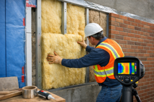
Infrared thermography on occupied buildings routinely reveals these bridges as bright lines on the exterior facade in winter conditions, confirming heat loss that the energy model assumed was not occurring. Beyond energy performance, the cold surface at the shelf angle creates a condensation risk at the interior face of the CMU directly behind the angle, which is a moisture problem that no amount of exterior insulation can correct once the thermal bridge is in place.
Requiring the contractor to demonstrate the shelf angle detail in the pre-installation mockup and requiring the special inspector to verify the detail at the first floor line before work proceeds above, are the two most effective quality controls available to the project team for this specific failure mode.
Making the Call: A Framework for the Decision
The choice between EIFS and mineral wool ci board over CMU in mid-rise Type I or II construction comes down to three factors: climate zone, construction schedule and fire code risk tolerance.
In Climate Zones 5 through 8, the vapor-open mineral wool assembly is the defensible choice for CMU substrates. The moisture physics favor it and the EIMA’s own guidance discourages barrier EIFS in those zones.
In Climate Zones 3 and 4, barrier EIFS with proper drainage detailing can perform acceptably on CMU if the air barrier is continuous and the terminations are executed correctly. That is a significant conditional.
On Type I and II construction where the cladding selection is still in flux at construction document phase, the noncombustible mineral wool assembly eliminates the NFPA 285 compliance chain entirely. That risk reduction has real value on fast-track projects where late design changes are the norm.
The project team that treats this as a cost-per-square-foot substitution is pricing in the material and ignoring the liability. Get the moisture analysis done against ASHRAE 160-2021. Run the effective R-value calculation with attachment corrections.
Confirm the fire code compliance path before the submittal package is assembled. The facility manager’s call six months after occupancy is the most expensive way to learn that the analysis was skipped.
Construction schedule is the third factor and the one most frequently underweighted in the analysis. A project that encloses CMU in October in Climate Zone 5 and installs EIFS before the following spring is taking on moisture risk that a mineral wool ci board assembly over a vapor-permeable WRB would not carry to the same degree.
If the schedule cannot be adjusted to allow adequate CMU drying time before EIFS enclosure, the assembly selection should reflect that constraint. Mineral wool’s vapor-open profile provides a margin of tolerance for construction moisture that barrier EIFS does not.
That margin is not a license for poor scheduling, but it is a meaningful performance buffer on projects where the schedule is driven by factors outside the design team’s control. Documenting that analysis in the basis of design, including the climate zone, the expected construction moisture conditions and the assembly’s drying potential against ASHRAE 160-2021 criteria, creates a record that supports the specification decision and demonstrates that the project team applied professional judgment rather than defaulting to the lowest first-cost option.