
EIFS vs. Adhered Masonry Veneer on Steel-Stud Walls: Comparing Long-Term Moisture Risk in North American Climate Zones
The Failure That Passed Every Inspection
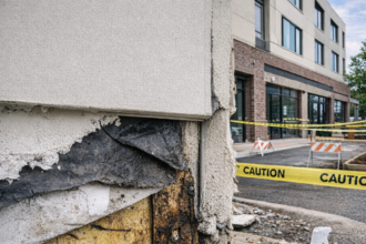
A six-story mixed-use building in Charlotte, North Carolina: IECC Climate Zone 4A: underwent partial adhered stone veneer removal during its year-seven warranty inspection. What the investigation team found behind the drainage mat was not a construction anomaly.
It was a pattern: widespread mortar bond failure across multiple elevations, corroded cold-formed steel framing at sill conditions and continuous polyisocyanurate insulation so thoroughly saturated it had lost measurable thermal resistance. The drainage mat had never drained.
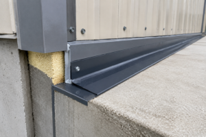
Water had entered at shelf angle terminations, migrated laterally behind the scratch coat and accumulated at horizontal blocking lines where the WRB lapped incorrectly over the angle’s vertical leg.
The project had passed all required inspections at each phase.
Several major insurers have now added adhered masonry veneer over steel framing to their elevated-risk cladding categories. That classification reflects claims data, not speculation.
The Charlotte scenario is not exceptional; it is representative of a failure mode that has become common enough to reshape underwriting criteria, drive post-2015 IRC code changes and generate a growing body of construction defect litigation concentrated almost entirely in the mixed-humid climate zones.
Two Systems, One Substrate, Divergent Risk Assumptions
Both systems covered here are defined precisely before comparing them. Drainage-type EIFS, governed by ASTM E2568 (Standard Specification for PB Exterior Insulation and Finish Systems), consists of an EPS or polyiso insulation board adhered or mechanically fastened to sheathing, a polymer-modified base coat reinforced with mesh, a primer and a textured finish coat, with a drainage medium between the insulation board and the WRB at the sheathing face.
Barrier EIFS eliminates that drainage medium and is no longer acceptable practice on commercial mid-rise construction. Adhered masonry veneer covers thin brick, adhered stone and manufactured stone veneer (MSV) bonded to a scratch coat and mortar bed applied over sheathing, with or without a drainage mat behind the mortar bed.
The shared substrate is cold-formed steel framing. That distinction matters because both systems behave differently on steel framing than on masonry backup or concrete.
Steel deflects, conducts heat and corrodes. Masonry backup does none of those things at the same magnitude.
Three axes structure the comparison that follows: drainage plane integrity, vapor management and substrate deflection tolerance. Specifiers routinely treat these as aesthetic choices.
They are not. They are hygrothermal performance choices with measurable consequences that show up in warranty claims seven to twelve years after substantial completion.
The cold-formed steel framing variable deserves more attention than it typically receives in product literature. A 6-inch 18-gauge stud at 16 inches on center has a thermal conductivity roughly 300 times that of the EPS insulation board it supports.
That conductivity creates localized cold spots at every framing member, which in turn creates localized condensation risk at the sheathing face behind both cladding systems. EIFS mitigates this by placing continuous insulation outboard of the framing.
Adhered veneer assemblies without equivalent outboard CI do not. The framing pattern becomes a moisture map in cold weather and that map shows up in infrared thermography as a grid of cold lines that correspond precisely to the locations where sheathing deterioration begins.
Specifiers who have seen that thermographic pattern once tend to specify outboard CI on every subsequent steel-framed project regardless of cladding type.
How Each System Manages Bulk Water: and Where Each One Fails
Drainage-type EIFS intercepts bulk water at the insulation board face. Water that penetrates the finish coat enters a drainage medium, typically a textured or dimpled mat laminated to the back of the insulation board and gravity-feeds to weep screed terminations at the base.
The system depends on two things being correct: the drainage medium must be continuous and the WRB at the sheathing face must be properly lapped and integrated at all penetrations. When those two conditions are met, EIFS manages bulk water reliably.
When the WRB laps are reversed at a window head or the weep screed is caulked by a painter, the system fails at that point.
Adhered masonry veneer takes a different approach. The mortar bed and scratch coat function as the primary water barrier, with a drainage mat or drainage mortar behind the veneer intended to manage water that penetrates the bond line.
The drainage plane is structurally discontinuous at every shelf angle, every penetration and every transition to a different cladding type. Those are precisely the locations where water concentrates.
Manufactured stone veneer carries the most documented failure data in this category. The NAHB Research Center’s investigations and the IRC’s 2015 and 2021 code responses reflect widespread bond and moisture failures in MSV applications.
IRC Section R703.12 (2021 edition) now mandates a drainage gap and a code-compliant WRB behind MSV, requirements that were absent from earlier editions and that code bodies added specifically because the field data demanded it. ASTM E331 governs water penetration testing for fenestration assemblies and is routinely used in EIFS system qualification testing.
No equivalent assembly-level water penetration test mandate exists for adhered veneer assemblies. That asymmetry in testing requirements partly explains the asymmetry in documented failure rates.
The drainage mat specification itself introduces a failure variable that is frequently underestimated. Not all drainage mats perform equivalently.
A 6-millimeter polyethylene drainage mat with a measured drainage coefficient of 0.15 gallons per minute per foot of width under ASTM E2925 test conditions performs materially differently from a 3-millimeter mat with a drainage coefficient of 0. 04. ASTM E2925 (Standard Test Method for Measuring Drainage Efficiency of Exterior Insulation and Finish Systems [EIFS] Drainage) provides the test protocol, but many project specifications reference drainage mat requirements without specifying a minimum drainage coefficient.
When the drainage mat is specified by product name only and the named product is substituted in the field with a lower-performing alternative, the drainage plane that the designer assumed is not the drainage plane that was built. That substitution is rarely caught during inspection because the mat is buried under mortar before anyone measures its performance.
Specifying a minimum drainage coefficient by ASTM E2925 test value, rather than by product name alone, closes that gap.
Vapor Management Across Climate Zones: Where the Physics Diverge
EIFS places continuous insulation outboard of the sheathing and framing. In heating-dominated climates, Zones 4 through 7, this keeps the sheathing warm and above the dew point during the heating season.
The water control layer and the thermal control layer occupy approximately the same plane. That alignment is a hygrothermal advantage that adhered veneer assemblies do not inherently replicate.
Adhered veneer assemblies typically place the drainage mat and mortar bed directly against the sheathing face with minimal outboard insulation. In Zone 5 and above, this produces a cold sheathing condition during winter.
Moisture-laden interior air that reaches the sheathing face through air leakage or vapor diffusion can condense there. In Zones 1 through 3, the vapor drive reverses seasonally and the risk shifts to inward-driven moisture during cooling season when the sheathing is warm and interior air is dehumidified.
Zone 4A is the highest-risk geography for this comparison. Charlotte, Atlanta and Nashville all sit in this mixed-humid zone where bidirectional vapor drive operates across the same annual cycle.
IECC 2021 Table C402.1.3 sets continuous insulation R-value requirements for commercial assemblies by climate zone. In Zone 4A, the code minimum for steel-framed walls is CI R-7.5 under the prescriptive path.
Drainage-type EIFS assemblies routinely achieve CI effective R-values of R-10 to R-15 depending on insulation board thickness and those values are tested at the assembly level. Adhered veneer assemblies rarely include equivalent outboard CI; when they do, the mortar bed and drainage mat introduce thermal discontinuities that reduce effective R-value below nominal.
WUFI hygrothermal modeling is the appropriate tool for zone-specific dew point analysis when comparing these assemblies. Running both assemblies through a WUFI simulation with Zone 4A climate data and realistic air leakage rates produces sheathing moisture content predictions that are difficult to argue with in a litigation context.
Specifiers who skip that step are accepting unknown risk.
The vapor retarder placement question compounds the zone-specific risk in adhered veneer assemblies. IBC Section 1404.3 and IRC Section R702.
7 both address vapor retarder requirements, but the prescriptive path does not always produce the correct vapor retarder class for a mixed-humid zone assembly. A Class II vapor retarder, such as kraft-faced insulation or a vapor-retarding primer, placed on the interior face of a steel-stud wall in Zone 4A creates a wall that resists drying in both directions during the shoulder seasons when vapor drive is transitional.
The sheathing becomes the moisture accumulation point. In a drainage-type EIFS assembly, the outboard insulation keeps the sheathing warm enough that this accumulation is limited and reversible.
In an adhered veneer assembly without equivalent outboard CI, the sheathing stays cold longer into the spring, the drying potential is lower and the accumulated moisture content can exceed the threshold for mold growth in OSB sheathing before summer temperatures drive it back out. WUFI Pro simulations run for a Zone 4A wall assembly with 3.5 inches of batt insulation, no outboard CI and a Class II interior vapor retarder consistently show peak sheathing moisture content in the 20 to 25 percent range by late February, which is above the 19 percent threshold for fungal growth in wood-based sheathing.
That result is not a modeling artifact; it matches the field conditions investigators find when they open these walls.
Steel-Stud Deflection and Its Asymmetric Impact on Each Cladding
Cold-formed steel studs deflect under wind load and thermal cycling. EIFS is engineered to accommodate that movement.
The EPS board and polymer-modified base coat system absorbs minor substrate deflection without cracking and EIMA (Exterior Insulation and Finish System Manufacturers Association) guidelines provide well-established control joint placement protocols for mid-rise applications. Vertical control joints at 10 to 12 feet on center and horizontal joints at each floor line are standard practice.
They work.
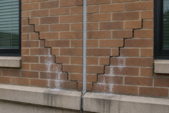
Adhered masonry veneer is a brittle finish bonded to a cementitious scratch coat. It cannot accommodate the same deflection.
Mortar joints crack. Scratch coats debond.
Veneer units fracture at mid-span or separate at the shelf angle above. IBC Section 1604.3 permits L/240 deflection under wind load for walls with brittle finishes.
That limit applies to adhered masonry veneer. Many structural engineers on mid-rise projects design stud framing to L/360 at glazing lines only, leaving veneer-clad bays designed to L/240 or sometimes less.
The difference between L/240 and L/360 on a 10-foot stud under a 30-psf wind load is not trivial; it is the difference between a scratch coat that stays bonded and one that doesn’t.
Masonry Veneer Manufacturers Association (MVMA) guidelines require horizontal expansion joints at each floor line and vertical joints at intervals consistent with the veneer unit’s coefficient of thermal expansion. In field practice, those joints are frequently omitted, filled with mortar by the mason or caulked over during punch-list.
Once they are gone, the only thing accommodating thermal and deflection movement is the bond line itself. That bond fails.
The thermal cycling component of deflection is frequently treated as secondary to wind load deflection in structural calculations, but in practice it drives more cumulative bond damage than a single wind event does. A dark-colored manufactured stone veneer on a south-facing elevation in Charlotte will experience surface temperatures ranging from below freezing in January to above 150 degrees Fahrenheit in July.
That 150-degree-plus temperature swing produces dimensional change in both the veneer unit and the steel framing behind it and those two materials have different coefficients of thermal expansion. The veneer unit wants to move one amount; the steel framing moves a different amount.
The mortar bond resists that differential movement until it cannot. The crack that results is typically hairline in its first season, wide enough to admit bulk water by year three and the entry point for the freeze-thaw damage that accelerates bond failure in years four through seven.
Specifying a sealant joint with a polyurethane or silicone sealant at every horizontal expansion joint location, with a minimum joint width calculated from the thermal expansion coefficient of the specific veneer product, is the only way to give the assembly somewhere to move. That calculation belongs in the project specification, not in a field decision made by the mason foreman.
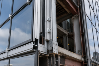
Transition Details: Where Both Systems Are Most Vulnerable
Every cladding assembly performs reasonably well at the field of the wall. Both systems fail at transitions: at shelf angles, at fenestration perimeters, at roof-to-wall intersections and at changes in cladding type.
The difference is in how each system’s geometry affects the difficulty of maintaining WRB continuity through those transitions.
EIFS transitions are difficult but geometrically manageable. The insulation board can be returned into a window rough opening, the WRB can be lapped onto the fenestration flange and the base coat can be terminated at a casing bead with sealant.
Failure happens when installers skip the casing bead, when sealant is applied over a dirty substrate or when the insulation board is not returned far enough into the opening. These are execution failures against a well-defined standard.
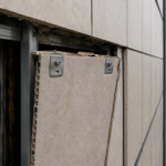
Adhered veneer transitions are geometrically harder. The mortar bed is rigid and typically 3/4 inch to 1 inch thick.
Getting a continuous WRB to lap correctly over a shelf angle’s vertical leg, under the mortar bed and onto the sheathing face below requires sequencing that conflicts with standard masonry installation practice. The WRB wants to be installed before the shelf angle.
The shelf angle is often installed after sheathing. The mortar bed goes on before anyone has verified WRB continuity behind it.
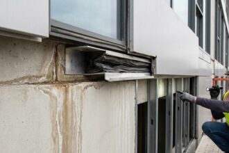
Once the mortar is set, the WRB condition behind it is uninspectable without destructive investigation. That is the specification-to-field gap that produces the Charlotte scenario.
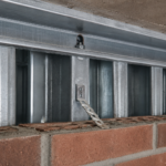
The shelf angle flashing detail is where this sequencing conflict produces the most consistent damage. A correctly detailed shelf angle condition requires the WRB to be lapped over the top of the angle’s vertical leg, a through-wall flashing to be integrated with the WRB at the shelf angle’s back face, weep holes or open head joints at the base of each veneer course above the angle and a sealant joint below the angle that is backed by a compressible backer rod.
That is four separate operations involving at least two trades, the framing contractor who installs the angle and the mason who installs the veneer, plus the WRB installer who is typically a third party. Coordinating those three trades in the correct sequence on a mid-rise project with a compressed schedule is where the detail breaks down.
The framing contractor installs the angle. The WRB installer laps over the sheathing but does not return the membrane over the angle’s vertical leg because the angle was not in place when the WRB was installed.
The mason arrives and installs the mortar bed directly against the angle without through-wall flashing because the specification did not call it out explicitly and the shop drawings did not show it. Water enters at the angle, runs behind the mortar bed and accumulates at the blocking line below.
That sequence is not hypothetical; it is the documented sequence in the Charlotte investigation and in a substantial number of similar claims files from Zone 4A and Zone 5A projects built between 2005 and 2018.
The roof-to-wall transition introduces a parallel sequencing problem. Where adhered veneer terminates at a parapet or at a roof membrane, the WRB must be continuous from the wall face onto the roof deck substrate.
In EIFS assemblies, the insulation board terminates at a casing bead, the WRB is lapped onto the roof assembly and the transition is geometrically straightforward. In adhered veneer assemblies, the mortar bed terminates at a horizontal cut that is difficult to flash without a custom-fabricated metal cap that integrates with both the roof membrane and the veneer face.
That cap is frequently omitted from the construction documents, left to the sheet metal contractor to detail in the field and installed without verification that the WRB behind the mortar bed is continuous through the transition. The result is an uninspected gap at the highest-stress transition in the assembly, directly above the zone where water concentration is greatest.
The Insurer’s View and What It Means for Specification Practice
When insurers add a cladding category to their elevated-risk list, they are publishing actuarial conclusions derived from claims data. Adhered masonry veneer over steel framing now sits in that category for several carriers.
That classification has direct consequences: higher premiums on wrap policies, more stringent special inspection requirements and, in some cases, carrier refusal to write the risk at all without peer review of the envelope design.
EIFS carries its own insurance history. The barrier EIFS failures of the 1980s and 1990s in the Southeast were severe enough to produce class-action litigation and drive the industry to drainage-type systems. That history is why AST