
Hybrid Unitized-Stick Curtainwall Systems at Building Corners and Re-Entrant Angles: Where the Transition Detail Fails and Why the Structural Mullion Continuity Gap Is the Performance Risk Nobody Budgets For
A 22-story mixed-use tower in the mid-Atlantic region passed its pre-installation mock-up testing with zero deficiencies. Both the unitized panels and the stick-built corner frames performed to AAMA 501.1 dynamic water penetration standards in isolation.
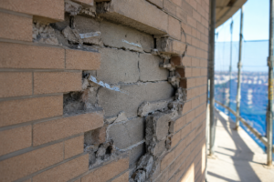
Within 14 months of occupancy, interior finishes on three re-entrant corner offices on floors 8 through 11 showed recurring water staining tracing directly to the structural mullion transition zone. That detail appeared on exactly zero shop drawing review comments and carried no line item in the contingency budget.
That project is not unusual. It is representative.
Why Hybrid Curtainwall Procurement Happens and Why Corners Pay the Price
Schedule pressure drives most hybrid procurement decisions. Unitized panels work for the repetitive field because the factory controls quality, lead times are predictable and erection is fast.
Corners, soffits and re-entrant conditions get assigned to stick-built framing because geometric complexity makes unitized fabrication impractical and the lead time for custom corner units often falls outside the procurement window.
The budget logic compounds the problem. Unitized panels and stick-built framing get specified and priced as independent line items.
The interface between them is not a line item. It is a coordination gap and it gets assigned to whoever is standing closest when the question gets asked on site.
Design-assist contracts fragment responsibility further. The unitized fabricator owns performance of the panel field.
The glazing contractor owns the stick-built corner frames. The structural steel subcontractor owns the embed plates.
Nobody owns the transition zone. AAMA CW-11 provides design guidance for curtainwall systems but does not address hybrid transition assemblies.
There is no governing standard that defines what a tested hybrid assembly looks like, which means the specification has no performance envelope to reference and the shop drawing reviewer has no benchmark against which to flag a deficiency.
The corner and the re-entrant angle are precisely where both systems’ standard tested configurations terminate simultaneously. That is the highest-stress location on the facade.
It is also the least-designed location in a hybrid procurement.
What makes this procurement pattern so persistent is that the cost argument appears sound at the time of award. A unitized panel field with stick-built corners typically pencils out at a lower combined bid number than a fully unitized system with custom corner units, because the corner unit tooling and engineering cost is absorbed into the unitized fabricator’s overhead rather than broken out as a visible line item.
The savings are real at bid time. The liability is deferred to post-occupancy, when the general contractor’s warranty exposure has already been priced and the facade subcontractors have moved to the next project.
Owners who have experienced this failure pattern on one building and then specified a fully unitized system on the next consistently report that the premium for corner unit integration is recovered within two years in avoided remediation costs alone. That data point does not appear in pre-bid cost analyses because it requires a long-term view that procurement schedules do not accommodate.
Anatomy of the Structural Mullion Continuity Gap
The discontinuity is geometric before it is anything else. A unitized panel system arrives from the factory with anchor bracket spacing set to the panel module, typically a 5-foot-0-inch grid coordinated to floor-to-floor height and mullion spacing.
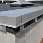
The stick-built vertical mullion at the corner return uses field-drilled embed anchors whose spacing is driven by structural steel framing layout, which rarely coincides with the unitized panel module. The result is a sill receptor that cannot align continuously across the transition and a pressure plate that terminates on one side of the corner without a mechanical connection to the framing on the other side.
Physically, this produces three compounding conditions. The sill receptor misaligns at the corner, breaking the continuous drainage path.
The pressure plate loses continuity at the mullion end, leaving the gasket uncompressed across a gap that may be only a quarter inch wide but is fully exposed to weather. The mullion end condition at the corner return becomes unrestrained because neither system’s anchor layout accounts for the other system’s reaction point.
Differential deflection makes this worse. Unitized systems are engineered to AAMA 501.4 racking tolerances as closed panel units; the panel deflects as a rigid frame.
Stick-built mullions deflect as individual members under the same wind load. At the interface, these two deflection behaviors produce relative movement that no single gasket profile currently in production is designed to accommodate across a structural discontinuity.
Thermal expansion adds a fourth variable. When the aluminum extrusion lengths in the two systems do not share a common anchor datum, their expansion and contraction cycles produce differential movement at the transition joint that is additive to the wind-induced deflection differential.
The sealant at that joint is being asked to absorb two independent movement cycles simultaneously.
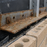
The anchor datum conflict deserves specific attention because it is the condition that structural engineers of record most frequently underestimate. On a typical mid-rise tower with a 13-foot floor-to-floor height, a unitized panel anchor bracket at 5-foot-0-inch spacing places anchors at elevations that have no relationship to the structural steel beam flanges driving the stick-built embed plate locations.
The embed plates for the stick-built corner mullion may land at 4-foot-2-inch and 8-foot-4-inch above finished floor, driven by the beam layout. The unitized panel brackets land at 5-foot-0-inch and 10-foot-0-inch.
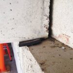
The sill receptor that must bridge these two anchor systems is being asked to span a mismatch that was never resolved in the structural design. When the glazing contractor arrives on site and finds that the two systems cannot be connected at a common elevation, the field solution is almost always a shimmed clip angle or a field-welded plate that transfers load through a geometry that was never analyzed.
That improvised connection becomes the structural mullion continuity gap and it is the point at which the building’s weather barrier has a permanent, unanalyzed weak spot.
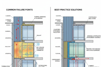
Air Leakage Pathways Specific to the Transition Zone
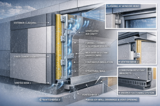
The pressure plate discontinuity at the corner mullion does more than leave the gasket uncompressed. It creates a bypass path that circumvents the unitized panel’s internal pressure-equalized drainage cavity entirely.
The rain screen principle that makes a unitized system work depends on pressure equalization within a closed cavity. Once the pressure plate loses continuity at the transition, the cavity is no longer closed.
Outside air pressure communicates directly with the cavity interior, short-circuiting the equalization mechanism and converting the drainage cavity into an infiltration pathway.
Stack joint alignment failure compounds this. When the unitized panel’s horizontal stack joint does not align with the stick-built system’s horizontal member at the corner return, the internal drainage path is interrupted.
Water that enters the cavity and should drain to a weep exits instead toward the structural mullion gap.
Air barrier continuity across the transition is where the four control layers fail in sequence. The unitized panel’s factory-applied air seal terminates at the panel edge.
The stick-built system’s field-applied air barrier must lap and bond to that factory substrate under field conditions, typically on a scaffold in variable temperature and humidity, with no controlled compression detail to ensure consistent contact pressure. That lap joint is not tested.
It is not detailed in most specifications. It is applied by a glazier whose primary quality metric is glass installation, not air barrier continuity.
ASTM E283 tests a uniform system assembly at a defined pressure differential. It provides no protocol for evaluating a hybrid transition condition.
The maximum allowable air infiltration under ASHRAE 90.1-2022 Section 5. 4 is 0.06 cfm per square foot.
Field-measured infiltration at undetailed hybrid transition zones routinely exceeds that threshold by a factor of three to five. That is not a code interpretation issue.
It is a design gap.
The energy consequence of that infiltration rate is not abstract. A hybrid transition zone on a 22-story tower with re-entrant corners on four elevations may represent 400 to 600 linear feet of transition joint.
At a measured infiltration rate of 0.25 cfm per square foot across a 12-inch-wide transition zone, the total uncontrolled air leakage through that joint alone can exceed the total allowable infiltration budget for a full floor plate under ASHRAE 90. 1-2022. That calculation does not appear in the energy model because the energy model assumes the curtainwall system performs to its tested assembly rating.
The tested assembly rating does not include the transition zone. The gap between the modeled performance and the actual performance is invisible until the utility bills arrive and by then the building has been accepted and the facade contractor’s performance bond has expired.
Commissioning agents who include blower door testing at the floor level adjacent to re-entrant corners as part of building enclosure commissioning per ASTM E779 consistently identify the transition zone as the dominant air leakage source on hybrid facade buildings. That finding appears in commissioning reports.
It almost never appears in the original specification as a required test location.
Water Infiltration Mechanics at Re-Entrant Angles
Re-entrant angles concentrate wind pressure. Building geometry at inside corners produces localized positive pressure differentials that exceed the design pressure assumptions used for the facade field by 20 to 40 percent in typical mid-rise configurations, a range consistent with both wind tunnel data and CFD modeling on rectangular tower geometries.
The facade detail at that location is therefore being loaded beyond its design basis from day one.
Water infiltration at the re-entrant angle differs from field-of-glass leakage in a specific way: entry occurs at the structural mullion gap under dynamic wind-driven rain conditions that produce pressure reversals the sealant joint cannot follow. A field sealant joint is designed to accommodate slow thermal cycling.
It is not designed to track rapid pressure oscillations under a storm event. The sealant debonds at the substrate interface under repeated dynamic loading and once the adhesion breaks, the joint admits water regardless of the sealant’s bulk integrity.
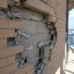
The failure is three-dimensional. Water entering the transition zone at the re-entrant angle travels horizontally along the sill receptor before exiting at an interior location displaced from the entry point by several feet.
This displacement is why post-occupancy investigations consistently misidentify the source. The staining appears at the interior corner.
The entry point is at the structural mullion transition, which may be a full panel width away.
Capillary action in the mullion gap functions as a secondary infiltration mechanism that operates independently of wind pressure. A gap of 0.010 to 0.
020 inches between aluminum surfaces is within the capillary range for water at standard surface tension. This means water infiltrates the gap during calm conditions following a rain event, with no wind pressure required.
AAMA 501.1 mock-up testing does not capture this mechanism. AAMA 501.2 hose testing at the transition zone specifically would expose it.
It is almost never specified at the transition zone.
The pressure concentration at re-entrant angles is a well-documented phenomenon in facade engineering, but the connection between that pressure concentration and the specific vulnerability of the hybrid transition detail is rarely made explicit in the design documentation. ASCE 7-22 Chapter 30 provides external pressure coefficients for components and cladding that account for corner zone amplification, designated as Zone 5 for walls in the standard’s pressure zone mapping.
The design pressure in Zone 5 at a re-entrant corner on a mid-rise building in Exposure Category C can exceed the field zone design pressure by 35 percent or more depending on building height and aspect ratio. The unitized panel system is tested to a design pressure that reflects the field zone loading.
The transition detail at the re-entrant corner is installed into a location where the actual loading exceeds that tested pressure. The specification should require that the transition zone assembly be tested to the Zone 5 design pressure, not the field zone pressure.
That requirement appears in almost no specifications currently in circulation. Adding it would not change the cost of the assembly.
It would change whether the assembly is designed to survive the actual load it will experience.
Sealant Fatigue and Long-Term Joint Degradation
The sealant at the hybrid transition joint performs a fundamentally different function than sealant anywhere else on the facade. It must simultaneously bridge a structural discontinuity, accommodate differential movement between two systems with different stiffness characteristics and maintain adhesion to dissimilar substrates: factory-primed aluminum extrusion on one side and field-cleaned stick mullion on the other.
No sealant manufacturer warrants their product for that combined condition. The warranty gap is not a technicality.
It reflects a genuine performance limitation.
Movement calculation mismatch is the root of the fatigue problem. Unitized panel movement is calculated as a closed-frame racking displacement and expressed as an interstory drift ratio.
Stick-built mullion movement is calculated as a cantilever deflection under tributary wind load and expressed as an absolute deflection at mid-span. These are not the same quantity and they do not add linearly at the transition joint.
Specifiers who simply apply the larger of the two movement values to the joint design are underestimating the actual joint demand.
Field substrate preparation is where the detail fails in execution even when it is correctly designed. Factory-primed aluminum accepts silicone or structural sealant predictably because the primer is applied under controlled conditions to a clean, dimensionally stable surface.
Field-cleaned stick mullion extrusion is cleaned by a glazier on a scaffold, often with isopropyl alcohol applied to a surface that has been exposed to concrete dust, form release compound and construction traffic. Adhesion test results on field-cleaned aluminum substrates show failure rates that would be unacceptable in a quality control program.
Most projects have no adhesion testing protocol at the transition zone.
Joint geometry compounds the fatigue. A properly designed sealant joint maintains a width-to-depth ratio of 2:1 to ensure the sealant can elongate without exceeding its tensile capacity at the bond line.
At the structural mullion transition, the joint geometry is determined by the gap between two systems that were fabricated independently. That gap is rarely 2:1. It is whatever it is when the two systems meet in the field.
The sealant manufacturer’s technical data sheet for a high-performance silicone sealant will typically list a movement capability of plus or minus 50 percent for a properly configured joint. That rating assumes a joint width of at least 3/8 inch, a width-to-depth ratio of 2:1, properly primed substrates of compatible chemistry and a curing environment within the temperature and humidity ranges specified on the data sheet.
At the hybrid transition zone, the joint width is determined by the as-built gap between two independently fabricated systems and may be as narrow as 3/16 inch. The depth is uncontrolled because there is no backer rod installation protocol for a gap that was not designed.
The substrate on the stick-built side has not been primed with the sealant manufacturer’s recommended primer because the primer selection requires knowing the substrate condition in advance and the substrate condition at the transition zone is not known until the two systems meet in the field. The curing environment on a scaffold at floor 9 in October in the mid-Atlantic region may fall outside the sealant manufacturer’s specified application temperature range on any given day.
Every one of those conditions degrades the sealant’s effective movement capability below its rated value. The joint that was already undersized for the combined movement demand is being installed under conditions that further reduce its performance.
The fatigue failure that results is not a product failure. It is a system design failure that the sealant is asked to compensate for and cannot.
Shop Drawing Review Failures That Let This Through
The shop drawing review process for hybrid curtainwall systems fails at the transition zone for a structural reason: the unitized fabricator submits drawings for the panel field and the stick-built contractor submits drawings for the corner frames, but nobody submits a drawing of the transition between them. The submittal packages are reviewed independently.
The reviewer who approves the unitized panel shop drawings is not looking at the stick-built corner framing submittal simultaneously. The transition detail exists in the gap between two approved packages.
Responsibility matrix language in the contract documents typically assigns coordination between systems to the general contractor. In practice, the GC has no technical basis for evaluating whether the transition detail performs.
That evaluation requires a facade engineer who has reviewed both submittals in parallel and specifically checked anchor spacing coordination, sill receptor alignment, pressure plate continuity and air barrier lap conditions at the interface. On most projects, that review does not happen.
The mock-up requirement is the last opportunity to catch the failure before installation. AAMA 501.1 mock-up testing should include the hybrid transition condition as a required element of the test assembly.
On the mid-Atlantic tower described at the opening of this article, the mock-up tested the unitized panel field and the stick-built corner frame as separate assemblies. The transition between them was never built into the mock-up.
It passed every test because the one condition that would fail was never tested.
Specify the transition zone explicitly in the mock-up scope. Require that the mock-up assembly include a minimum of one full unitized panel module transitioning to a stick-built corner return with all anchor conditions, sill receptor connections, pressure plate terminations and air barrier laps as they will be installed in the field.
That single specification requirement would have prevented the failure on floors 8 through 11.
The shop drawing review failure is also a scheduling failure. Unitized panel shop drawings are typically submitted and reviewed on a fast-track schedule because the fabrication lead time is long and the erection schedule depends on early release.
Stick-built corner framing shop drawings are submitted later because the lead time is shorter and the GC treats the corner frames as a fill-in scope that can be resolved after the panel field is locked. The result is that the unitized panel shop drawings are approved before the stick-built corner framing geometry is known.