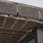
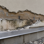
- Forensic investigations consistently find that undersized deflection track slots convert non-load-bearing CFS studs into compression struts under drift.
- ASCE 7-22 seismic drift demands at typical mid-rise story heights exceed the standard catalog slot size of three-quarters of an inch.
- AISI S240-15 Section B4.2 requires slot length to equal twice the calculated drift plus construction tolerance but this formula is rarely applied in practice.
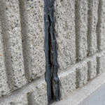
- Stair-step cracking in masonry veneer at consistent story-height intervals is a diagnostic indicator of slip-track binding not differential settlement.
- The structural engineer of record must explicitly size and document the required slot length in contract documents before shop drawings are issued.
Slip-Track Sizing at Masonry Veneer: Stop Undersizing the Slot
A five-story mixed-use building in the Mid-Atlantic region, less than seven years old, presents with stair-step cracking at every third course of brick veneer above the second-floor shelf angle. The owner’s attorney initially attributes it to settlement.
Forensic investigation tells a different story: the slip-track slot at the top of the cold-formed steel backup wall was specified at ¾ inch, while calculated story drift under ASCE 7-22 wind loading demanded a minimum of 1⅝ inches of free vertical movement. The masonry veneer had been acting as an unintended load-bearing element since the first significant wind event.
Nobody on the project team caught it because nobody owned the calculation.
Why the Slip-Track Detail Exists and What It Is Actually Supposed to Do
The deflection track at the top of a non-load-bearing cold-formed steel stud wall serves one structural purpose: it decouples the stud assembly from the floor or roof structure above so that vertical load cannot transfer into framing that was never designed to carry it. AISI S100-16 Section C3.6 governs axial load in wall studs and AISI S240-15 Section B4 establishes the deflection track requirements for non-load-bearing walls.
The detail works by allowing the stud top to translate vertically within a slotted track while maintaining lateral restraint in the out-of-plane direction.
Engineers frequently conflate these two functions. Lateral bracing is real and necessary.
Vertical slip is equally necessary and far more often compromised. When the slot is undersized, the stud top bears against the deflection track web under drift and converts from a non-load-bearing partition element into a compression strut.
That conversion happens silently. No alarm sounds.
The framing continues to look correct on the shop drawing and in the field until the cladding begins to crack.
The masonry veneer cladding on the outside of that assembly depends entirely on the backup wall remaining kinematically free. The veneer ties connect the brick wythe to the CFS framing.
If the framing moves vertically under load, the tie system carries forces it was never designed to resist. That is not a serviceability issue.
It is a structural conflict embedded in the detail from day one.
What makes this failure mode particularly difficult to catch in design review is that the deflection track looks identical whether the slot is ¾ inch or 2½ inches. The distinction lives in a dimension that rarely appears on architectural drawings, is frequently absent from structural drawings and defaults to whatever the CFS framing manufacturer stocks in the catalog.
The AISI S240-15 commentary is explicit that the track slot must be sized by calculation, not by catalog selection. That instruction does not always reach the person selecting the track.
Forensic reviews of distressed buildings consistently find that the CFS detailer made a catalog selection, the structural engineer assumed the detailer would perform the calculation and the facade engineer assumed both of them had already resolved it. The assumption chain is the failure.
How Much Drift Are We Designing For? ASCE 7-22 Story Drift Demands in Mid-Rise Construction
ASCE 7-22 Table 12.12-1 sets allowable seismic story drift at 0. 007hsx for masonry veneer-clad structures in Risk Category II.
At a 13-foot story height, that is 1.09 inches of allowable drift. At 14 feet, it is 1.18 inches.
A ¾-inch default slot fails both cases before you account for construction tolerance. The math is not subtle.
Wind drift is a separate matter. ASCE 7-22 Table 12.12-1 addresses seismic only.
Wind serviceability criteria come from ASCE 7-22 Commentary Section C1.3 and from project-specific criteria that structural engineers establish independently. H/400 to H/200 is the typical range for mid-rise commercial construction and at H/400 for a 14-foot story, you are looking at 0.42 inches of wind drift per floor.
That number compounds across stories. A building with four floors of CFS backup wall accumulates drift at each level independently; calculating drift only at the roof and applying it uniformly to every floor is a mistake that shows up repeatedly in forensic reviews.
IBC 2021 Section 1604.3 requires that serviceability be considered under appropriate loads, but it does not prescribe specific wind drift limits. That discretion lands on the structural engineer of record.
When that engineer documents the drift value in a schedule on structural drawings but does not explicitly communicate the required slip-track slot dimension to the facade designer or CFS detailer, the gap opens. And it stays open until the building cracks.
The mid-rise escalation issue deserves direct attention. Four- to eight-story CFS-framed buildings are exactly the building type where drift accumulation is most consequential and most frequently miscalculated at the detail level.
At lower heights, drift values are small enough that even an undersized slot sometimes survives without visible distress. At greater heights with concrete or structural steel frames, the backup wall system is typically designed by a facade engineer with explicit drift accommodation in the scope.
The four-to-eight-story range falls between those two conditions. The structural engineer of record often uses CFS framing as a partition system specification rather than a facade support system specification and the drift accommodation requirement gets treated as a partition detail rather than a cladding structural requirement.
Seismic zone also matters in ways that are not always reflected in the slot sizing. A Risk Category II building in Seismic Design Category C with a 13-foot story height and a concrete moment frame lateral system may see amplified story drifts well above the 0.007hsx allowable if the frame is designed to the allowable limit.
The amplified drift, calculated using Cd from ASCE 7-22 Table 12.2-1, is the value that governs slip-track sizing, not the elastic drift from the analysis model. Using the elastic drift without applying Cd is an error that reduces the apparent drift demand by a factor of four to six depending on the system and it produces a slot size that is unconditionally inadequate.
The Specification Gap: Where Deflection Track Sizing Goes Wrong
Three failure modes appear consistently in forensic investigations of masonry veneer distress on CFS backup walls. First, the structural engineer calculates drift correctly but does not communicate the required slot length to the facade engineer or CFS detailer.
Second, the CFS detailer defaults to the manufacturer’s standard catalog slot, typically ¾ inch, without performing a project-specific calculation. Third, the facade engineer specifies veneer tie embedment assuming a rigid backup wall, not one that moves under load.
None of these failures requires negligence. They require only the absence of explicit coordination.
Structural drawings show drift values in a schedule. CFS shop drawings show a standard deflection track detail.
Masonry specifications reference MasterSpec Section 04 20 00 without inserting a performance requirement for backup wall drift accommodation. No single document closes the loop.
AISI S240-15 Section B4.2 provides the minimum slot length formula: slot length must equal at least two times the calculated drift plus the construction tolerance. That formula is not ambiguous.
The problem is that it lives in the CFS framing standard, which the structural engineer may reference but which the CFS detailer may never open when selecting a catalog track. Manufacturer catalogs for deflection track list slot lengths of ¾ inch, 1½ inches and occasionally 2 inches as standard options.
None of those catalog entries reference AISI S240-15 Section B4.2. The detailer selects a slot length the same way they select a stud gauge: by matching a number in a table to a number in the specification. If the specification does not contain a slot length requirement, the smallest standard option fills the blank.
Construction tolerance compounds the problem immediately. A ¾-inch slot with a ⅜-inch erection tolerance leaves only ⅜ inch of live drift capacity before the building experiences a single load event.
At that point, the assembly is already compromised. The slot was consumed during installation.
The fix is not complicated. The structural engineer of record must explicitly size the slot in the contract documents, not leave it to a shop drawing submittal.
That is a specification decision, not a shop drawing coordination issue. The shop drawing submittal process is a verification step, not a design step.
Treating it as a design step for slip-track sizing is how projects end up with ¾-inch slots on buildings that need 2½ inches. The structural engineer sizes the slot, puts the dimension on the drawings and in the specification and the shop drawing confirms compliance.
That sequence works. The reverse sequence, where the shop drawing proposes a dimension and the engineer reviews it, only works if the engineer has a target value to check against.
Without that target value documented in the contract, the review is a formality with no technical basis.
What Happens to the Masonry Veneer When the Slip Track Binds
When the stud top bears against the deflection track web, the stud becomes a compression strut. Load transfers through the veneer tie into the masonry unit and induces diagonal tension in the mortar joints.
The result is stair-step cracking at mortar joints near the top of each story panel. Forensic teams routinely misdiagnose this pattern as differential settlement or thermal movement because the crack geometry is similar.
Settlement cracks, however, do not correlate with story height intervals. Slip-track binding does.
The diagnostic distinction is worth understanding in detail. Differential settlement produces cracking that concentrates at transitions in foundation type or soil condition, typically at building corners, re-entrant corners or locations where a loaded bay meets an unloaded bay.
The crack pattern may be stair-step in brick veneer, but it will be continuous across multiple stories and will not repeat at regular vertical intervals. Slip-track binding produces cracking that repeats at each story panel, correlates with the location of the deflection track above each shelf angle and is most severe at the upper stories of the building where cumulative drift effects are greatest.
Thermal cracking produces horizontal cracks at shelf angle locations, not diagonal cracks within the panel field. When a forensic investigator sees stair-step cracking that repeats at consistent vertical intervals matching story heights, slip-track binding is the first hypothesis to test, not the last.
The tie anchorage failure mode is the more serious concern. Veneer ties fabricated to ASTM A1008 wire tie specifications or corrugated tie profiles are designed to carry tension and compression along their primary axis.
They transfer out-of-plane wind load from the veneer to the backup wall. They are not designed to carry vertical shear from axial load transfer through the stud.
When that vertical load arrives at the tie, one of three things happens: the tie fractures at its bend, the tie pulls out of the mortar joint embedment or the masonry unit cracks at the tie location.
TMS 402-22 Section 6.2.4 governs veneer tie design requirements and none of those provisions anticipate vertical load transfer from a bound slip track. The tie spacing assumptions built into most masonry specifications assume the backup wall is kinematically free.
When it is not, the tie system operates outside its design envelope from the first wind event. Pull-out testing of ties from distressed buildings has shown embedment failures at loads well below the published capacity values when the tie has been subjected to combined shear and tension rather than pure tension.
The mortar joint embedment that performs adequately under out-of-plane wind load alone degrades rapidly when cyclic vertical shear is superimposed. That degradation is not visible from the exterior until the masonry unit itself begins to crack or the tie pulls free entirely.
The forensic record on this failure mode is consistent. Distress appears within the first three to seven years of occupancy, after the building has experienced several significant wind or seismic events.
By then, the owner has a litigation problem, not a maintenance problem.
Calculating the Required Slot Length: A Repeatable Design Procedure
AISI S240-15 Section B4.2 gives the framework. The required slot length equals two times the calculated story drift plus the applicable construction tolerance.
In practice, the calculation sequence runs as follows.
Start with the structural engineer’s drift calculation for the governing load case at each floor level. For seismic, use the amplified drift from ASCE 7-22 Table 12.12-1, which means applying the deflection amplification factor Cd to the elastic story drift from the analysis model before comparing to the allowable drift limit.
For a special reinforced masonry shear wall system, Cd equals 3.5 per ASCE 7-22 Table 12. 2-1. For a cold-formed steel special bolted moment frame, Cd equals 3.
5 as well. Using the elastic drift output from the structural model without applying Cd is a common error that understates the demand by the full Cd factor.
For wind, use the project-specific serviceability drift limit, typically H/400 or as established in the structural basis of design. Take the larger of the two values at each floor.
Multiply by two. AISI S240-15 requires the factor of two because the stud must be free to move in both directions from its installed position.
A stud centered in a ¾-inch slot has only ⅜ inch of movement capacity in each direction, which is why the formula doubles the drift demand. In practice, studs are rarely centered in the track at installation.
Field measurements from CFS framing inspections show that studs are commonly installed at or near one end of the available slot range, which means the effective movement capacity in the critical direction may be even less than the theoretical half-slot value. The factor of two in the formula partially accounts for this, but it assumes the stud is installed at the slot midpoint.
Specifying a construction tolerance explicitly and requiring the contractor to center studs within the slot at installation is a reasonable quality control measure that costs nothing to write into the specification.
Add construction tolerance explicitly. A reasonable tolerance for CFS framing is ⅜ inch per AISI S240-15 commentary guidance, though project specifications should state the assumed tolerance so the contractor is accountable to it.
At a 13-foot story height with 0.007hsx seismic drift and H/400 wind drift governing, the required slot at minimum is 2 × 1. 09 inches plus ⅜ inch, yielding approximately 2.56 inches.
Round up to the next available track size. Specify that dimension on the structural drawings and repeat it in the CFS framing specification section.
Do not leave it to the shop drawing process.
When standard catalog track sizes do not reach the required slot length, custom track is available from most CFS manufacturers at modest cost premium. A project requiring a 2½-inch slot that cannot be met by a standard 2-inch catalog track should specify custom track in the contract documents, not accept a substitution during shop drawing review.
The cost difference between standard and custom deflection track on a five-story building is measured in hundreds of dollars. The cost of forensic investigation, remediation and litigation on a building with bound slip tracks is measured in hundreds of thousands.
Veneer Tie Detailing at the Head Condition: What the Tie Must Tolerate
The veneer tie at the top of each story panel sits closest to the slip-track condition and carries the highest risk of overload when the slot binds. Standard tie spacing per ASTM C1063 and TMS 402-22 Section 6.2.4 addresses tributary area and out-of-plane load transfer.
It does not address the vertical shear demand that arrives when the backup wall locks up.
Best practice requires a gap between the top course of masonry and the shelf angle or floor structure above. TMS 402-22 recommends a minimum ⅜-inch soft joint at horizontal supports to accommodate differential movement between the masonry wythe and the structure.
That soft joint must remain free of mortar droppings during construction; contamination of the joint is a field execution failure that eliminates the intended movement capacity before the scaffolding comes down. Inspectors reviewing masonry construction should treat soft joint contamination as a structural deficiency, not a workmanship comment.
A mortar-filled soft joint is a hard joint. It transfers load.
Removing contaminated mortar from a completed soft joint location after the scaffolding is down is a difficult and expensive operation that rarely restores the full intended gap dimension.
The tie immediately below the soft joint should be specified as a two-piece adjustable tie rather than a corrugated or wire tie. Two-piece adjustable ties accommodate vertical differential movement between the backup wall and the veneer wythe without transferring that movement as shear into the masonry.
The outer and inner components of a two-piece adjustable tie can translate relative to each other along the tie axis, which means that when the backup wall moves vertically under drift, the tie accommodates that movement rather than transmitting it as a shear force into the mortar joint. Corrugated ties and wire ties have no such accommodation.
They are rigid in the vertical direction relative to their installed position and any vertical displacement of the backup wall relative to the veneer wythe loads the tie in shear at the mortar joint interface. This is not a code requirement in most jurisdictions.
It is a best practice recommendation based on observed field performance and the cost difference is negligible compared to the cost of forensic investigation and litigation.
Specify the tie type, the soft joint dimension and the joint material (a closed-cell backer rod with sealant, not mortar) explicitly in Section 04 20 00. Do not rely on the masonry contractor to make this decision in the field. The masonry contractor’s default is mortar.
Mortar is what they have. Mortar is what goes in joints.
Without an explicit specification requiring a compressible filler and sealant at the soft joint location, the joint will be filled with mortar on a significant percentage of projects and the intended movement accommodation will not exist when the building needs it.
Closing the Coordination Loop Before the Building Goes Vertical
The deflection track slot size is a structural calculation result. It belongs on structural drawings, in the CFS framing specification and in the masonry specification as a coordination requirement.
When it appears in none of those locations, the default ¾-inch catalog slot fills the void and the building pays for it within a decade.
The facade engineer reviewing CFS shop drawings should verify the specified slot length against the structural drift schedule before approving the submittal. If the structural drawings do not include a drift schedule with explicit slot sizing, that is a red flag worth raising in a formal RFI before framing begins.
Waiting until the masonry cracks to ask the question is the pattern this industry keeps repeating. An RFI issued during shop drawing review costs a few hours of engineering time.
A forensic investigation with destructive opening of the wall assembly, laboratory analysis of tie specimens and expert witness preparation costs orders of magnitude more and it happens after the damage is done and the building is occupied.
Project delivery method affects where this coordination gap is most likely to appear. In design-bid-build delivery, the structural engineer of record has the clearest opportunity to size the slot in the contract documents before any contractor is involved.
In design-build delivery, the CFS framing subcontractor may be engaged before the structural engineer has completed the drift analysis and the framing layout may be set before the slot size is calculated. In that sequence, the design-build team must establish a process for communicating the structural engineer’s drift results to the CFS detailer before shop drawings are finalized, not after.
Construction manager at-risk delivery presents similar risks when the CFS framing package is bid and awarded before the facade package, which is common. The CFS detailer selects a track, the masonry contractor designs the tie layout and neither document references the other until a problem appears.
ASCE 7-22 drift demands in mid-rise construction are not going to get more lenient. The buildings going up today in Risk Category II mixed-use occupancies with masonry veneer on CFS backup walls need slot lengths in the 2-inch to 3-inch range at typical story heights.
Specify it. Document it.
Hold the field to it. The alternative is a forensic investigation seven years from now where everyone on the project team points at someone else’s drawing set.