



Expansion Joints in Brick Veneer Facades Keep Failing: and Sealant Is Not the Problem
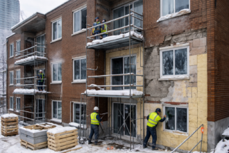
A forensic investigation on a seven-year-old institutional brick veneer facade reveals stair-step cracking radiating outward from every fourth expansion joint bay. The joints were repaired with premium polyurethane sealant just 18 months prior.
When the consultant pulls the original structural drawings alongside the facade specification, the expansion joint width is listed at 3/4 inch on both documents. The thermal movement calculation, never formally performed, would have required 1-1/8 inch minimum at that climate zone and bay length.
The sealant never failed. The joint was simply never large enough to do its job.
The Repair Cycle That Never Ends
The failure signature is consistent across projects: recurring stair-step cracks at or adjacent to expansion joints, sealant debonding at cohesive failure planes and efflorescence tracking from joint edges. All of it reappears within 12 to 24 months of the previous repair.
That recurrence interval is the signal. It corresponds almost exactly to one to two full thermal cycles, which tells you the repair addressed the symptom and left the cause untouched.
The repair-and-repeat cycle is the masonry industry’s most reliable indicator that root cause analysis was never performed. Owners authorize sealant replacement.
Contractors install it correctly. The joint fails again.
Everyone assumes the contractor used the wrong product or didn’t prime the substrate. Nobody asks whether the joint was ever the right size.
The central diagnostic question is this: was the joint width calculated for this project or was it defaulted from a standard detail? IIBEC forensic case literature and practitioner surveys consistently document that cosmetic joint repair without dimensional correction fails within one to two thermal cycles.
The number is not surprising. A joint sized at 3/4 inch that requires 1-1/8 inch of accommodation is operating at roughly 150% of its geometric capacity before any sealant performance variable enters the equation.
What makes this pattern particularly damaging from an owner’s perspective is the cumulative cost. A single sealant replacement on a mid-sized institutional facade runs between $40,000 and $90,000 depending on access conditions and joint count.
When that repair fails in 18 months and the cycle repeats two or three times before anyone commissions a forensic investigation, the total expenditure on ineffective repairs frequently exceeds the cost of the original facade remediation that would have corrected the geometry. The repair budget becomes a recurring line item in the facility management plan and the building never actually gets fixed.
Owners who push back on forensic investigation costs are often the same owners who have already spent three times that amount on sealant replacements that accomplished nothing.
Practitioners who have worked through multiple cycles of this pattern report a consistent dynamic: the first repair is treated as a warranty claim, the second as a contractor quality issue and the third as a product failure. By the time the fourth cycle begins, the original contractor is gone, the warranty has expired and the owner is paying full market rate for a repair that will fail on the same schedule as every previous attempt.
The forensic investigation that should have been commissioned after the first recurrence is finally authorized after the fourth, at which point the masonry has sustained cumulative damage that a correctly sized joint would have prevented entirely.
How Expansion Joint Width Gets Assigned
Trace the typical design workflow and the accountability gap becomes obvious. The structural engineer sets deflection criteria and notes “provide expansion joints per masonry specification.
” The architect or facade consultant defaults to BIA Technical Note 18 or a project standard detail without performing project-specific movement calculations. The detail gets issued.
The contractor builds to the detail. Nobody flags the discrepancy because nobody ran the numbers.
Three inputs must be reconciled to size a joint correctly: thermal differential (delta-T for the climate zone), the coefficient of thermal expansion for the specific masonry unit and the cumulative bay length between fixed points. Miss any one of those inputs and the calculated width is wrong.
BIA Technical Note 18A, Design and Detailing of Movement Joints, Table 1 provides thermal movement coefficients for clay brick at 3.6 x 10⁻⁶ in/in/°F. The formula for required joint width is straightforward: multiply the coefficient by the delta-T by the bay length, then add a factor for moisture expansion of clay units (approximately 0.0002 in/in irreversible) and divide by the sealant’s rated movement capacity to establish minimum joint width.
The note explicitly states that values must be adjusted for project-specific delta-T. That adjustment step is where most projects fail.
The 3/4-inch default persists because it originated in moderate-climate assumptions and migrated into project standard details that travel from project to project without geographic recalibration. In IECC Climate Zone 3 coastal installations, it may be adequate.
In Zone 5 and above, it is not.
The migration of standard details across climate zones is a structural problem in how design firms manage their specification libraries. A detail developed for a healthcare project in Charlotte gets pulled into the base specification for a university project in Milwaukee because the facade assembly type is similar and no one flags the geographic difference as a variable requiring recalculation.
The detail is technically correct for its origin climate. It is systematically wrong for its destination.
Firms that maintain a single standard masonry detail without a climate zone qualifier embedded in the document are building this failure mode into every project that pulls from that library.
The bay length variable compounds the problem in ways that are easy to overlook during design review. A 20-foot bay and a 30-foot bay with identical thermal conditions require joint widths that differ by 50%.
Projects with irregular column spacing or facade geometry that produces variable bay lengths between fixed points need joint widths calculated individually for each bay, not a single dimension applied uniformly across the facade. Applying the maximum calculated width uniformly is conservative and acceptable.
Applying the minimum or an average is not. Forensic investigations on facades with variable bay spacing frequently document that the longest bays are the first to crack, exactly as the math predicts, while the shorter bays remain intact and are incorrectly cited as evidence that the joint width was adequate.
The Structural Engineer’s Deflection Assumption Does Not Match the Facade Movement Calculation
This is the contractual and technical gap that produces the most damage and it is almost never formally addressed at design development.
Structural engineers size expansion joints to accommodate inter-story drift and floor deflection under live and dead load. IBC 2021 Section 1604.3 establishes deflection limits for exterior walls and the controlling limit for masonry veneer attached to a flexible backup is typically L/600.
That calculation is performed correctly. The problem is that it addresses only one movement source.
Facade engineers must account for thermal cycling, moisture expansion of clay units, creep in the backup structure and differential movement between the veneer and the steel or concrete frame. These movement sources are additive, not alternative.
A joint sized only for structural deflection will be consumed by thermal movement alone in the first summer cycle, leaving zero reserve capacity for moisture expansion or creep. The joint is geometrically bankrupt before the building completes its first year of service.
The contractual gap is equally significant. In most project delivery structures, no single party is explicitly responsible for reconciling structural deflection allowances with facade thermal movement budgets.
The structural engineer’s drawings reference the spec. The spec references BIA.
BIA’s formula requires inputs no one has formally provided. ASCE 7-22 commentary addresses differential movement at cladding attachment points but does not require reconciliation with thermal movement calculations for the veneer itself.
The result is a calculation that everyone assumes someone else performed.
The concept of a movement budget resolves this. Total available joint width must be allocated across all movement sources with a minimum 25% reserve for sealant working capacity limits.
If the structural deflection contribution is 0.25 inch and the thermal contribution is 0. 75 inch, the joint needs to be at least 1.25 inches before the reserve factor is applied.
That number is not 3/4 inch. It is not close to 3/4 inch.
The floor deflection contribution deserves specific attention on long-span concrete structures. A post-tensioned concrete frame with 40-foot spans can produce measurable creep deflection over the first three to five years of service that continues to accumulate well past the building’s first thermal cycle.
ACI 318-19 Section 24.2 addresses long-term deflection multipliers and the values are not trivial: a multiplier of 2. 0 applied to the immediate deflection for sustained loads means the long-term floor movement can be double what the structural engineer’s initial calculation shows.
If the facade engineer is sizing the expansion joint against the immediate deflection value without applying the long-term multiplier, the joint is undersized from the day the building opens, before thermal movement or moisture expansion contribute a single additional increment of demand. This specific interaction between long-term structural creep and facade joint sizing is one of the least-documented contributors to early-cycle expansion joint failure on concrete-framed buildings and it rarely appears in the forensic analysis unless the investigating consultant specifically requests the structural engineer’s long-term deflection documentation.
Backer Rod and Sealant Selection Control Geometry, Not Capacity
The mechanical role of the backer rod is frequently misunderstood and that misunderstanding drives expensive specification decisions that accomplish nothing.
Backer rod controls sealant depth-to-width ratio, targeting 1:2 per ASTM C1193. It prevents three-sided adhesion, which would constrain the sealant’s ability to deform. It establishes the working geometry of the joint.
It does not add movement capacity to an undersized joint. A correctly installed backer rod in a 3/4-inch joint that needs 1-1/8 inch of accommodation does not change the fundamental geometric inadequacy.
Sealant elongation ratings exist in a similar context. A high-performance silicone or polyurethane rated at plus or minus 50% movement capability under ASTM C920 Class 50 still fails if the joint is sized at 3/4 inch and requires 1-1/8 inch of total movement.
The sealant is being asked to perform at over 100% of its rated capacity before any reserve exists. Class 50 is not a correction for an undersized joint.
It is a rating that assumes the joint was sized correctly.
The specification habit of upgrading sealant class in response to joint failure is one of the most persistent and costly errors in masonry facade maintenance. It substitutes a more expensive consumable for a geometric correction that costs nothing to implement at design stage.
ASTM C1193 is explicit: joint width must be sized so that sealant movement does not exceed rated elongation under service conditions. The standard places the obligation on joint sizing, not sealant performance.
The backer rod material selection introduces a secondary variable that practitioners frequently overlook when diagnosing repeat failures. Open-cell polyurethane backer rod, closed-cell polyethylene backer rod and bi-cellular backer rod each have different compression characteristics and different responses to temperature extremes.
Closed-cell polyethylene rod, the most commonly specified type, becomes significantly stiffer at low temperatures and can exert outward pressure on the sealant bead during winter contraction cycles if it was installed at a compression ratio that did not account for thermal stiffening. That outward pressure creates a tensile condition at the sealant-to-substrate bond line that accelerates adhesion failure in joints that are already geometrically stressed.
Specifying the correct backer rod material for the climate zone and verifying that the installation compression ratio falls within the manufacturer’s temperature-adjusted range are steps that almost never appear on a standard masonry inspection checklist and their absence means this failure contributor goes undiagnosed even when a forensic investigation is performed.
The 1:2 depth-to-width ratio target in ASTM C1193 is a minimum performance requirement, not a preference. Sealant installed deeper than half the joint width cannot deform freely across its full cross-section, which concentrates strain at the bond line rather than distributing it through the sealant body.
That strain concentration is what produces the cohesive failure planes that look like sealant material failure in the field. The sealant did not fail because it was the wrong product.
It failed because the geometry forced it to carry more strain than its cross-section could distribute. Correcting the depth-to-width ratio without correcting the joint width reduces the rate of cohesive failure but does not eliminate it, because the joint is still being asked to accommodate more total movement than its width permits.
Climate Zone Amplification Is Concentrating Failures in Specific Geographies
The thermal delta-T problem is quantitative and it is not subtle. A brick veneer facade in IECC Climate Zone 5, covering Chicago, Minneapolis and similar continental markets, experiences a service temperature range of approximately -20°F to +140°F when solar gain on dark brick is accounted for.
That produces a delta-T of 160°F. A Zone 3 coastal installation might see 60°F delta-T across the same service life.
For identical bay lengths, the required joint width in Zone 5 is nearly three times larger than in Zone 3. The 3/4-inch default that performs adequately in coastal California is a systematic failure waiting to happen in the upper Midwest.
Climate pattern shifts are compressing the window between design assumptions and actual performance. Wider temperature swings and more frequent freeze-thaw cycles are accelerating the movement demand on assemblies that were already undersized for their original climate zone.
Forensic investigations in Zone 5 and Zone 6 markets are documenting failure rates that cannot be explained by sealant material selection or installation quality alone. The geometry was wrong from the beginning and changing climate conditions are exposing that error faster than the original design life would have predicted.
The practical implication for specifiers is direct: any project in Climate Zone 5 or above with clay brick veneer and bay lengths exceeding 20 feet should treat 3/4-inch expansion joints as a presumptive deficiency until a project-specific calculation demonstrates otherwise.
The solar gain component of the delta-T calculation deserves more attention than it receives in standard practice. ASHRAE 90.1 and the BIA Technical Notes both acknowledge that surface temperature on dark masonry under direct solar exposure can exceed ambient air temperature by 50°F to 70°F in summer conditions.
A dark brown or charcoal brick on a south or west elevation in a Zone 5 climate is not experiencing a 160°F delta-T. It is experiencing something closer to 210°F to 230°F when the solar gain increment is properly accounted for.
That additional 50 to 70 degrees of effective temperature range translates directly into additional joint width demand. A facade with dark brick on south and west elevations and light brick on north and east elevations has different expansion joint requirements on each elevation, a condition that almost no project specification acknowledges and almost no standard detail accommodates.
Specifying a single joint width across all elevations without accounting for solar gain differentials by orientation is a systematic underestimate of movement demand on the exposures that receive the most solar loading, which are also the exposures that experience the most visible cracking in forensic investigations.
Zone 6 projects in markets like Minneapolis, Duluth and northern New England introduce an additional variable in the form of freeze-thaw cycle frequency. A joint that is geometrically adequate for annual thermal range but positioned adjacent to a flashing condition that allows water infiltration will experience accelerated deterioration from freeze-thaw cycling within the joint cavity itself.
The water that enters through an improperly lapped flashing or an inadequately sealed joint edge freezes in the joint cavity during winter contraction, expands against the sealant and the adjacent masonry and accelerates both sealant adhesion failure and masonry spalling at the joint face. The thermal movement calculation addresses the annual range.
It does not address the mechanical damage from freeze-thaw cycling within a wet joint. Both conditions must be controlled and controlling freeze-thaw damage requires watertight detailing at the joint edges, not a wider joint.
The Specification-to-Field Translation Problem
Even when a designer performs the movement calculation correctly and specifies the right joint width, field execution introduces a second failure mode that forensic investigations regularly document.
Masons set expansion joint widths by eye or by template and templates are often cut from the previous project’s standard detail regardless of what the current specification requires. A 1-1/8-inch joint specified on the drawings becomes a 3/4-inch joint in the field because the template in the truck is 3/4 inch and no one checked.
This is not a craftsmanship failure. It is a quality assurance failure and it belongs to the project team.
Special inspection requirements for masonry under IBC 2021 Chapter 17 do not explicitly require dimensional verification of expansion joint widths as a discrete inspection item. That gap means the field condition is rarely caught during construction and is only discovered forensically after cracking begins.
Closing this gap requires a project-specific special inspection checklist that includes joint width measurement at each expansion joint location before sealant installation, with dimensional tolerances stated in the specification. ASTM C1193 provides installation guidance but does not substitute for a project-specific inspection protocol.
The water control layer is also at risk in this scenario. An undersized or improperly backed joint that fails under thermal cycling creates a direct breach in the assembly’s first line of defense against bulk water entry.
Efflorescence at joint edges is not cosmetic. It is evidence that water is moving through the backup and depositing salts as it evaporates.
The crack pattern is the visible symptom. The water intrusion is the liability.
The special inspection gap has a practical consequence that extends beyond the expansion joints themselves. When the special inspector’s checklist does not include joint width verification, the inspector has no contractual basis for issuing a non-conformance notice when the field condition deviates from the specification.
The deviation is not caught, not documented and not corrected. The building is accepted with joints that are systematically undersized and the first indication that something is wrong arrives 12 to 18 months later when the stair-step cracking begins.
At that point, the construction records show that special inspection was performed and no deficiencies were noted, which creates a documentation problem for anyone attempting to establish that the contractor built out of specification. Adding joint width verification as an explicit line item on the special inspection checklist, with a stated tolerance of plus 1/8 inch and minus zero, gives the inspector the authority and the obligation to catch the deviation while the masonry is still accessible and correctable.
The tolerance specification itself requires careful drafting. A tolerance stated as plus or minus 1/8 inch on a 1-1/8-inch joint allows the joint to be built as narrow as 1 inch, which may still be inadequate for the calculated movement demand.
The minus tolerance should be zero or should be explicitly tied to the movement calculation: the joint width shall not be less than the calculated minimum width shown on the drawings. That language makes the calculation the controlling dimension rather than the detail and it prevents the field from treating the specified width as a nominal value subject to standard construction tolerances that were developed for structural elements, not for precision-dependent facade components.
Pre-installation mockups that include expansion joints built to the specified width, inspected and measured before the mockup is accepted, provide a second verification point that catches template errors before they propagate across the entire facade. The mockup requirement is already present in most masonry specifications for color and texture approval.
Extending it to include dimensional verification of expansion joints adds no significant cost to the mockup process and creates a documented baseline that the field crew has physically built the correct joint width at least once before production masonry begins.
What the Next Design Review Should Require
The correction is not complicated. It requires assigning explicit responsibility and performing a calculation that takes less than an hour.
Every masonry veneer project in Climate Zone 4 and above should require a formal movement accommodation calculation as a deliverable, performed by the facade engineer or envelope consultant, reconciled with the structural engineer’s deflection assumptions and reviewed before the expansion joint detail is issued for construction. That calculation should establish the total movement budget, allocate contributions from thermal cycling, moisture expansion and structural deflection, apply the 25% sealant reserve factor and specify the resulting minimum joint width as a project-specific dimension, not a reference to a standard detail.
Specifiers who continue to issue 3/4-inch expansion joints on continental climate projects without performing that calculation are not specifying to BIA Technical Note 18A. They are ignoring it.
The note provides the formula. The formula requires the inputs.
Running the numbers is the job.
The deliverable format matters as much as the calculation itself. A movement accommodation calculation submitted as a standalone memo that references the structural engineer’s deflection values, states the project-specific delta-T, identifies the masonry unit coefficient and shows the arithmetic for each bay length is a document that can be reviewed, checked and incorporated into the project record.
It creates accountability. If the joint fails and litigation follows, that memo establishes that the calculation was performed, the inputs were project-specific and the specified joint width was derived from the result.
The absence of that memo, which is the current condition on most projects, establishes only that no one performed the calculation. That is not a defensible position for a licensed design professional.
The reconciliation meeting between the facade engineer and the structural engineer should be a scheduled deliverable at the design development phase, not an informal conversation that may or may not happen. The agenda for that meeting has three items: the structural engineer presents the deflection values that will govern facade joint sizing, the facade engineer presents the thermal and moisture movement calculations for each bay and the two parties agree on a total movement budget and minimum joint width before the detail is issued.
That meeting takes 30 minutes. The forensic investigation that replaces it takes months and costs orders of magnitude more.
Firms that build this coordination step into their standard design workflow as a required milestone, rather than leaving it to individual project managers to schedule or skip, are the firms whose masonry facades do not appear in the forensic case literature.