

Glazed Curtainwall-to-Opaque Wall Transitions: Air Barrier Continuity Failures, Thermal Bridging at the Slab Edge and Why the Interface Detail Is the Most Litigated Zone in the Facade
A 14-story mixed-use tower in the mid-Atlantic region fails its whole-building blower door test at substantial completion. Not because of the curtainwall system, which tests within spec.
Not because of the opaque precast panel wall, which also performs independently. The failure originates entirely at the 18-inch zone where the two systems meet at each slab edge, a condition repeated across 11 floor levels.
The forensic report identifies no single responsible trade, because no single trade was ever assigned ownership of that detail in the contract documents. That building is not an outlier.
It is the norm.
The Interface Nobody Owns: Why This Zone Fails Before Construction Begins
The curtainwall subcontractor’s scope typically terminates at the back of the mullion anchor or at the slab edge bracket. Full stop.
The opaque wall trade, whether masonry, precast, EIFS or metal panel, begins scope at the sheathing or backup wall face, not at the curtainwall anchor condition. Between those two defined scopes sits a gap of four to twelve inches of unassigned territory and that gap is where air barrier continuity breaks by default, not by accident.
This is a contract document failure before it is ever a field failure.
Division of responsibility language in standard AIA contract structures does not resolve this condition. The AIA A201 general conditions distribute responsibility by trade scope and when no trade’s scope explicitly includes the transition connection, the connection does not get made.
Facade specifications that treat the curtainwall and the opaque wall as separate specification sections without a coordinating transition detail section are writing the failure into the project before the first anchor is set.
The problem compounds when the general contractor’s project manager assumes that the curtainwall subcontractor, as the more technically sophisticated trade, will naturally extend scope to cover the gap. That assumption is never documented, never priced and never executed.
The curtainwall foreman installs what the shop drawings show. The shop drawings show what the specification requires.
The specification stops at the anchor. The result is a gap that every trade walks past for the duration of construction because no one has been told it is their problem.
Preconstruction coordination meetings rarely surface this condition because the agenda is driven by schedule and sequencing, not by air barrier continuity. A pre-installation envelope coordination meeting that specifically maps the air control layer from one system to the other, traces it across the transition zone on a dimensioned detail and assigns a named subcontractor to each segment of that layer is the only preconstruction mechanism that reliably catches the gap before work begins.
Most projects never hold that meeting.
NIBS Guideline 3, the National Institute of Building Sciences’ Exterior Enclosure Technical Requirements for the Commissioning Process, identifies transition zones between dissimilar facade systems as a primary commissioning risk category precisely because this contractual vacuum is predictable and recurring. Naming it in a guideline has not fixed it.
Explicit assignment in the facade specification is the only mechanism that does.
What the Updated Energy Codes Are Now Exposing
For decades, transition zone failures were discovered through occupant complaints, visible moisture damage or energy bill anomalies. All of those are lagging indicators that obscure root cause and make litigation attribution nearly impossible.
That era is ending.
ASHRAE 90.1-2022 Section 5. 4.
3. 1.
2 sets a maximum continuous air leakage rate of 0.40 cfm/ft² at 0. 3 in.
w. g.
(75 Pa) for commercial building envelopes. The 2021 IECC Section C402.5.1.2 establishes parallel testing protocol requirements and, in many adopting jurisdictions, mandates third-party testing or commissioning agent verification.
That verification produces documented deliverables. Those deliverables become litigation exhibits.
The threshold itself is the issue. A 0.40 cfm/ft² limit at 75 Pa is achievable when the field membrane is properly applied and lapped.
It is not achievable when the transition zone between curtainwall and opaque wall is undetailed, because that zone alone can generate air leakage rates that push a compliant building over the threshold. The curtainwall tests clean.
The opaque wall tests clean. The assembly fails.
Attorneys love that fact pattern.
What makes that fact pattern particularly damaging in litigation is that the individual trade contractors can each produce test data showing their system performs within specification. The curtainwall subcontractor submits mock-up test results.
The opaque wall contractor submits field adhesion and continuity documentation for the fluid-applied membrane. Both documents are accurate.
Neither document addresses the transition zone, because neither scope included it. The owner is left holding a building that fails the whole-assembly test with no clear contractual party to pursue, which is precisely why these cases settle expensively and slowly rather than resolving cleanly.
Intermediate testing protocols, specifically zone-by-zone pressurization using temporary barriers to isolate floor-level segments of the facade, can locate the failure zone during construction rather than at substantial completion. ASTM E779 and ASTM E1827 both provide methodologies applicable to partial-building testing.
Some commissioning agents are now requiring floor-by-floor interim testing on tall buildings as a contract deliverable, with hold points tied to the construction schedule. That approach costs money.
It costs significantly less money than a post-occupancy remediation campaign on 11 floor levels of unassigned transition zone.
Note that all code adoptions are local and subject to amendment. Jurisdictions adopting the 2021 IECC or ASHRAE 90.1-2022 by reference may have modified the testing thresholds or compliance pathways.
Verify the adopted edition and any local amendments before specifying a compliance strategy. What the code says in the base document and what it requires in your jurisdiction are not always the same number.
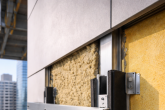
Anatomy of the Failure: How Air Barrier Continuity Is Broken at the Slab Edge
The curtainwall system’s air control layer runs through the pressure plate, gasket and back pan assembly. It is a face-sealed or drained-and-back-vented system whose air control layer does not naturally extend to the slab edge.
The back pan terminates. The slab edge is exposed.
The opaque wall’s air barrier, whether fluid-applied, self-adhered membrane or continuous board insulation with taped joints, terminates at the curtainwall anchor condition. It is rarely detailed to lap, connect or transition to the curtainwall’s air control layer.
The two systems approach each other from opposite directions and stop short of contact.
At the slab edge, a third geometry interrupts both. The slab soffit, the perimeter angle or embed and the firestopping assembly all occupy the same zone where the air barrier plane needs to be continuous.
The firestop contractor installs safing insulation and intumescent wrap after the air barrier membrane has been applied, physically severing the membrane. This is not a sequencing error by an incompetent contractor.
It is the required sequence for a tested firestop assembly. The membrane has to go in before the safing and the safing installation damages the membrane.
No one has assigned responsibility for repairing that damage.
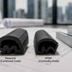
The geometry of the back pan termination makes the problem worse. Most curtainwall back pan assemblies terminate with a sealant joint at the slab edge and that sealant joint is the intended air seal for the curtainwall system at that location.
The sealant is applied by the curtainwall installer to a substrate that may include the perimeter angle, the slab edge form board or the concrete itself, depending on the project. When the opaque wall air barrier membrane is later applied by a different trade, it approaches that sealant termination from the other direction and is expected to lap onto it.
The lap dimension, the substrate preparation requirements and the compatibility between the sealant and the membrane are almost never specified. Field crews make those decisions on the fly and the decisions they make are driven by what is physically accessible at the time of installation, not by what the air barrier system manufacturer’s tested detail requires.
Fluid-applied membrane manufacturers publish transition details that show their product lapping onto curtainwall back pan flanges, slab edges and perimeter angles. Those details are tested in controlled laboratory conditions with clean substrates and full access.
The field condition involves a perimeter angle that may be partially obstructed by the curtainwall anchor hardware, a slab edge that has been contaminated by concrete form release agent and a membrane applicator working from a swing stage with limited reach into the transition zone. The tested detail and the field condition are not the same thing and the specification rarely acknowledges that gap.
ASTM E2357 governs air leakage testing of air barrier assemblies. The transition connection detail must be tested as part of the air barrier assembly, not as the field membrane in isolation.
Most project specifications do not require this. They specify the field membrane product and its application requirements and they stop there.
The transition detail, which is the highest-risk location in the entire assembly, gets no performance verification requirement at all. That is a specification gap that practitioners need to close explicitly.
Thermal Bridging at the Slab Edge: The Performance Penalty That Compounds the Problem
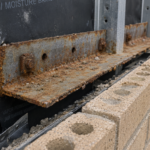
The perimeter slab edge is one of the highest linear thermal transmittance locations in a commercial facade. A steel embed plate or continuous perimeter angle connecting the curtainwall to the slab creates a direct conductive path through the insulation plane.
This is not a marginal penalty.
ISO 10211 and THERM modeling of typical curtainwall-to-slab-edge conditions produce linear thermal transmittance (psi) values ranging from 0.15 to 0. 45 W/m·K depending on anchor geometry, embed depth and whether a thermal break is incorporated.
At the high end of that range, the slab edge condition alone can degrade the effective R-value of the adjacent opaque wall assembly by 20 to 35 percent when calculated over the full floor-to-floor height. Nominal R-value is what the insulation label says.
Effective R-value is what the assembly actually delivers after accounting for thermal bridges. They are not the same number and specifying one while measuring the other is how projects fail thermal performance compliance.
The THERM modeling exercise also reveals a secondary problem that practitioners frequently miss: the thermal bridge at the slab edge creates a surface temperature depression on the interior face of the spandrel assembly that can fall below the dew point of interior air under winter design conditions. On a building with an interior relative humidity maintained at 35 percent and an outdoor design temperature of 0 degrees Fahrenheit, the interior surface temperature at an unbroken perimeter angle can drop to 45 to 50 degrees Fahrenheit, well within the condensation risk range for typical office occupancy.
That condensation does not always produce visible water. It produces elevated moisture content in adjacent gypsum board, insulation and framing, which shows up years later as mold, corrosion or deteriorating finishes.
The thermal bridge and the air leakage failure at the transition zone are separate mechanisms that produce overlapping damage patterns, which is one reason forensic attribution in these cases is so difficult.
Continuous insulation reduces but does not eliminate this bridging. Cladding attachment brackets and shelf angles create point and linear thermal bridges that penetrate the CI plane.
A thermally broken perimeter angle, properly specified and detailed, can reduce the psi value to the 0.05 to 0. 10 W/m·K range.
That reduction is worth specifying. The thermal break material selection matters: load-rated structural thermal breaks behave differently under combined axial and shear loading than simple pad-type isolators and the structural engineer of record needs to be part of that conversation before the detail is issued for bid.
Fiberglass-reinforced nylon thermal break materials rated for structural applications, such as those conforming to the load tables published by manufacturers like Schöck or Halfen, carry defined allowable load values for axial, shear and moment conditions. Those values need to be verified against the actual anchor loads from the curtainwall engineer’s calculations before the thermal break is specified.
A thermal break that is adequate for a lightweight metal panel system may be undersized for a heavy precast panel or stone cladding system using the same anchor geometry. The structural engineer’s review of the thermal break selection is not optional and the specification should require it explicitly as a submittal review item rather than leaving it to the curtainwall subcontractor’s judgment.
The Spandrel Condition: Where Three Trades Collide and Nobody Wins
The spandrel zone at the slab edge is where curtainwall, opaque wall and firestop trades physically occupy the same 12 to 18 inches of space in a sequence that the contract documents almost never coordinate. The curtainwall installer sets the back pan and applies sealant to the slab.
The opaque wall trade installs the air barrier membrane on the backup wall and terminates it at the anchor condition. The firestop contractor installs the perimeter fire barrier per a listed assembly, which requires specific safing depths, compression ratios and intumescent product placement that are determined by the listed assembly, not by the air barrier detail.
The listed firestop assembly governs. It has to.
IBC Section 715 and ASTM E2307 govern perimeter fire containment and a tested and listed assembly cannot be field-modified to accommodate an air barrier membrane that was not part of the tested configuration. When the air barrier membrane laps into the firestop zone, it either gets cut or gets buried under safing in a way that breaks its continuity.
Both outcomes produce the same result: a gap in the air control layer at the highest-risk location in the facade.
The sequencing problem is worth mapping explicitly because it illustrates why field coordination cannot solve this without prior specification-level resolution. The curtainwall installer typically works from the outside, setting anchors and back pans floor by floor as the building is enclosed.
The opaque wall air barrier applicator follows the curtainwall installation, working from scaffolding or a swing stage. The firestop contractor works from the interior, typically after the floor deck above is poured and the perimeter gap is accessible from inside.
By the time the firestop contractor arrives, the air barrier membrane has already been applied in the transition zone. The firestop contractor’s listed assembly requires a specific safing compression ratio, which means the safing has to be cut and packed to a defined depth.
That process physically contacts and frequently damages the membrane that the air barrier applicator installed weeks earlier. No one calls for a repair because no one’s scope requires one.
Hilti, 3M and Specified Technologies Inc. each publish listed perimeter fire barrier assemblies that include provisions for air barrier membrane compatibility in some configurations.
Those listings are not universal and the specific membrane product, thickness and lap condition must match the tested configuration exactly for the listing to apply. Specifiers who write a generic air barrier membrane specification and a generic firestop specification without cross-referencing the two are creating a condition where field compatibility is impossible to verify and likely to fail.
The solution is not to fight the firestop sequence. The solution is to specify a transition membrane or accessory that is compatible with the listed firestop assembly and that can be installed after the firestop work is complete, restoring air barrier continuity without compromising the listed assembly.
This requires coordination between the air barrier system manufacturer’s tested details and the firestop assembly listing before the project goes to bid. It cannot be resolved in the field by a foreman making judgment calls.
What a Coordinated Transition Detail Actually Requires
A transition detail that maintains air barrier continuity across the curtainwall-to-opaque-wall interface needs four things specified explicitly: a defined air control layer in the curtainwall back pan assembly with a termination point that can receive a transition membrane; a compatible transition membrane or tape product that bridges from the curtainwall termination to the opaque wall air barrier; a firestop assembly that is selected with the transition membrane condition in mind; and an assigned trade responsible for installing and inspecting the transition connection.
That last item is the one that kills projects when it is missing.
The specification language for trade assignment needs to be unambiguous. Phrases like “coordinate with adjacent trades” or “provide continuity at transitions” are not assignments.
They are invitations to dispute. The specification should state, in the transition zone work item, that the named trade, typically the air barrier applicator or the curtainwall subcontractor depending on project structure, is responsible for the complete and continuous air seal from the curtainwall back pan termination to the opaque wall air barrier field membrane, including all accessory materials, substrate preparation and repair of any damage caused by subsequent trades.
That language puts a dollar value on the scope, which means it gets priced, which means it gets executed.
The submittal process is the second enforcement mechanism. Requiring the curtainwall subcontractor and the opaque wall contractor to submit a joint coordination drawing showing the air control layer path through the transition zone, with product identifications and lap dimensions at every connection point, forces the resolution of compatibility questions before work begins.
If the two subcontractors cannot produce a coherent joint drawing, the incompatibility is visible to the design team before it becomes a field failure. Most projects do not require this submittal.
Adding it to the specification costs nothing and eliminates the most common source of post-construction disputes.
The specification should name the transition zone as a distinct work item, assign it to a single trade or require a written coordination plan signed by all affected subcontractors before work begins. The envelope commissioning agent, if one is engaged under NIBS Guideline 3 protocols, should include the transition zone in the pre-installation inspection scope and require photographic documentation of the air barrier connection before it is concealed by cladding or insulation.
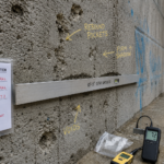
Infrared thermography during pressurization testing can locate discontinuities in the transition zone after the fact, but finding them at substantial completion is expensive. Finding them during construction is not.
The Specification Is the Last Line of Defense
Every forensic investigation I have conducted on