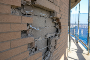

- A Kansas City veneer anchor pull-out failure traced directly to an outdated SDC classification shows how code cycle gaps cause real structural damage.
- ASCE 7-22 shifted SDC boundaries across the central US and Pacific Northwest reclassifying sites that were confidently designed under older hazard models.
- TMS 402-22 prescriptive tie requirements differ categorically between SDC B and SDC C with no interpolation provision and no transition language.
- Corrugated ties lose 40 to 60 percent of their capacity under cyclic loading making them structurally inadequate the moment ground motion exceeds static test conditions.
- Specifying adjustable two-piece ties across any site within 10 percent of an SDC threshold costs thousands of dollars and prevents remediation costs in the hundreds of thousands.
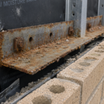
A masonry veneer on a six-story mixed-use building in the Kansas City metro area began showing systematic anchor pull-out during a moderate seismic event. The ties were not defective.
They were specified to the prescriptive minimums of Seismic Design Category B while the updated ASCE 7-22 hazard maps had reclassified the site as SDC C. The project had been permitted under the 2018 IBC with older spectral acceleration values and the specification contained no language addressing the boundary condition.
The failure was entirely predictable and entirely preventable.
Why Seismic Design Category Boundaries Are Not Lines on a Map
SDC classification is not a fixed geographic line. It is a function of site-specific spectral response accelerations, specifically S_DS and S_D1, combined with the building’s Risk Category under ASCE 7-22 Table 11.6-1 and Table 11.
6-2. The USGS 2018 National Seismic Hazard Model, which ASCE 7-22 adopted as its basis, shifted SDC boundaries meaningfully across the central United States, Pacific Northwest and parts of the Intermountain West. Missouri, Oklahoma and Oregon all saw contour shifts significant enough to reclassify sites that had been confidently designed as SDC B under ASCE 7-16.
A single parcel can straddle interpolated hazard contours. Two buildings on the same city block can carry different SDC classifications based on minor differences in site class or the interpolated spectral values at each lot centroid.
That is not a theoretical edge case. It is a documented consequence of how probabilistic hazard maps work.
Site class D soil, which is common across the Missouri River floodplain and much of the Mississippi embayment, amplifies short-period spectral accelerations enough to push S_DS values across the SDC B-to-C threshold even when the underlying bedrock hazard would not. The site class determination in the geotechnical report is therefore not a passive background input.
It is an active variable in the SDC calculation and a change in boring interpretation between preliminary and final geotechnical reports can shift the SDC without anyone in the design team flagging the change.
Specifiers routinely treat SDC as a binary input rather than a probabilistic output. They pull the classification from a geotechnical report, enter it into a master specification checkbox and never revisit it.
That approach creates a false sense of precision in tie selection and leaves no margin for the uncertainty embedded in the hazard model itself. The USGS hazard model carries explicit epistemic uncertainty bands.
The SDC threshold values in ASCE 7-22 Table 11.6-1 are not uncertainty-adjusted. A site with an S_DS of 0.497 is classified SDC B.
A site with an S_DS of 0.500 is classified SDC C. The code treats that 0.003 difference as categorical.
The hazard model does not.
What the Prescriptive Tie Requirements Actually Require and Where They Stop
TMS 402-22 Chapter 12 establishes prescriptive anchor requirements differentiated by SDC and the differences are not cosmetic. SDC A and B allow standard corrugated ties at a maximum tributary area of 2.67 square feet per anchor.
SDC C requires adjustable two-piece ties with positive mechanical attachment to the backup structure. SDC D and above require engineered anchor systems with specific stiffness and ductility criteria that must be demonstrated through testing.
The prescriptive path ends at the SDC boundary. There is no interpolation provision.
No blended requirement. No transition language.
TMS 402-22 Section 12.2.2 is explicit on this point and the commentary reinforces it: prescriptive provisions are not intended for interpolation between categories. If your site is SDC C, you use SDC C requirements.
If your permit was issued under a hazard model that said SDC B and the current model says SDC C, you have a gap.
IBC 2021 Section 2109.2.1 defers to TMS 402 for seismic provisions without adding any transition guidance of its own. The code assumes the SDC determination has been made correctly and completely.
Specifiers using CSI MasterFormat Section 04 21 13 as a base rarely carry SDC-conditional language beyond a single classification checkbox in the product selection table. The specification reads as though SDC is a permanent, settled fact.
It is not.
The tributary area limit is a particularly common failure point. SDC B allows 2.67 square feet per tie, which at standard coursing translates to a tie at every other course at 16 inches on center horizontally.
SDC C reduces that allowable tributary area and requires the two-piece adjustable format specifically because the adjustable slot accommodates differential movement between the veneer and backup that a rigid corrugated tie cannot. That slot is not a manufacturing convenience.
It is a performance requirement. Removing it by substituting a corrugated tie removes the only deformation accommodation mechanism in the connection.
The specification must make that distinction explicit and it must make clear that the two requirements are not interchangeable at the specifier’s discretion or the contractor’s convenience.
This is where the liability exposure lives. The code is clear.
The specification is not.
The Specification Gap: How Projects Fall Through the Boundary Condition
Most project specifications identify a single SDC at project outset and propagate that classification through all envelope sections without revisiting it at permit phase or construction document completion. The SDC determined during schematic design, often from a preliminary geotechnical report using the older hazard model, becomes the permanent design basis by default.
The problem compounds when jurisdictions adopt code cycles on different schedules. A municipality still enforcing the 2018 IBC while the state has adopted the 2021 IBC creates a condition where the AHJ’s governing SDC and the engineer’s design basis SDC can differ.
Neither party flags the discrepancy because each is working from a different reference document and neither specification section requires reconciliation. In Kansas and Missouri, municipal adoption of the 2021 IBC has lagged state-level adoption by two to four years in several jurisdictions, creating exactly this condition for projects that crossed the design-to-permit timeline during the transition window.
Geotechnical reports frequently deliver site class and spectral acceleration values without flagging proximity to SDC threshold contours. The geotechnical engineer is not the facade engineer.
The report gives you the numbers; it does not tell you that your S_DS value is 0.04 below the SDC C threshold and that a one-step-up in site class would push you over. That proximity warning is nobody’s assigned responsibility, which means it belongs to the envelope specifier.
A specifier who receives a geotechnical report showing S_DS of 0.46 and records SDC B in the specification without noting that the SDC C threshold is S_DS of 0. 50 has created a document that will not survive a post-event forensic review.
The number was in the report. The proximity was calculable.
The decision to specify to the boundary was available and was not made.
A 2023 survey by the Masonry Veneer Manufacturers Association found that fewer than 15% of commercial project specifications reviewed contained explicit language addressing SDC boundary or transition conditions. Change orders and value engineering substitutions during construction routinely swap tie systems without re-evaluating SDC compliance, particularly when the original specification language is ambiguous about the governing category.
A substitution request that replaces an adjustable two-piece tie with a corrugated tie at equivalent tributary area spacing will pass through a submittal review process that is checking product dimensions and corrosion resistance ratings, not cyclic test compliance. The reviewer approves the substitution because the specification did not prohibit it clearly enough to make the prohibition visible at the shop drawing stage.
Structural Behavior Differences That Make the Gap Dangerous
SDC B corrugated ties are tested for tensile and compressive capacity under static loading per ASTM E488-15. They are not required to demonstrate cyclic ductility, energy dissipation or deformation compatibility under reversed loading. That is a deliberate code decision for low-seismic applications.
It becomes a structural liability the moment the ground motion exceeds what a static-only test validates.
SDC C and above require ties to accommodate in-plane differential movement between the veneer and backup while maintaining out-of-plane load transfer. That is a fundamentally different performance demand.
The tie must deform, recover and transfer load repeatedly across multiple cycles without losing embedment integrity or fracturing at the connector body.
Stiffness mismatch makes this worse. A rigid corrugated tie connected to a flexible cold-formed steel stud backup concentrates demand at the mortar joint embedment, which is the most brittle link in the load path.
The stud deflects under lateral load; the tie, being stiffer than the mortar joint, transfers that differential displacement directly to the embedment zone rather than distributing it across the connector body. The mortar breaks first.
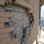
Published cyclic test data from the Concrete Masonry Association of California and Nevada documents 40 to 60% reductions in cyclic capacity versus static capacity for corrugated tie profiles. Under moderate seismic shaking at Modified Mercalli Intensity VI to VII, corrugated ties in SDC C conditions have demonstrated pull-out at mortar embedment depths that exceed the prescriptive minimums for SDC B.
The tie was installed correctly. It simply was not the right tie.
ICC-ES AC58 acceptance criteria for masonry veneer anchors require cyclic testing for SDC C and above precisely because static test results do not predict cyclic performance.
The failure sequence in a corrugated tie under cyclic loading follows a consistent pattern that forensic investigations have documented repeatedly. The first cycle at moderate amplitude causes micro-cracking at the mortar-to-tie interface.
Subsequent cycles widen those cracks and begin to work the tie body within the mortar pocket. By the fifth to tenth cycle at the same amplitude, the tie is rocking within a partially fractured mortar socket rather than transferring load through bearing.
Tensile capacity measured at that point is a fraction of the static pull-out value recorded in the ASTM E488 test. The veneer panel is no longer anchored in any meaningful sense.
It is resting against the backup, held in place by gravity and friction until the next out-of-plane demand removes it entirely. That sequence plays out in minutes during a seismic event.
It is irreversible once the mortar socket fractures.
Hybrid Tie System Logic: Building a Specification That Covers Both Sides of the Boundary
The practical solution is to specify to the higher SDC’s prescriptive requirements across the entire building envelope when a site falls within a reasonable proximity band of an SDC threshold contour. Define that band explicitly in the specification.
A site within 10% of the S_DS or S_D1 threshold value for SDC C should be specified to SDC C requirements regardless of which side of the line the interpolated value places it on.
Adjustable two-piece ties that satisfy SDC C requirements under TMS 402-22 Section 12.2.2 are not significantly more expensive than corrugated ties at scale. The cost differential on a mid-rise commercial project is measured in thousands of dollars, not tens of thousands.
The cost of a veneer remediation after anchor pull-out is measured in hundreds of thousands. Specifying to the higher category is not conservative; it is rational.
The specification language must do more than name the SDC. It must require the contractor to verify that any substituted tie system carries tested cyclic performance data meeting ICC-ES AC58 for the specified SDC.
Value engineering substitutions that swap an adjustable two-piece tie for a corrugated tie because “both are listed in the spec” represent a compliance failure enabled by vague specification language. Close that gap explicitly: state that corrugated ties are not permitted when the design SDC is C or above and require submittals to include the governing test report, not just an ICC-ES listing number.
The specification should also address the slot dimension in adjustable two-piece ties as a performance parameter, not just a dimensional tolerance. TMS 402-22 requires that the adjustable slot accommodate the differential movement expected between the veneer wythe and the backup system under the design lateral displacement.
For a six-story cold-formed steel framed building in SDC C, that differential can reach 3/8 inch at upper floors under the design story drift. A tie with a 1/4-inch slot does not satisfy that requirement regardless of its ICC-ES listing.
The listing number alone does not tell the reviewer whether the slot dimension matches the project’s drift demand. The specification must require the contractor to demonstrate that match explicitly, with calculations or manufacturer confirmation referenced to the structural engineer’s drift analysis.
That requirement closes the gap between a product that is listed for SDC C and a product that actually performs for the specific building’s SDC C demand.
Field Coordination Failures That Compound the Design Gap
Even a correctly written specification fails if field coordination does not carry the SDC requirement forward to the masonry subcontractor’s shop drawing review. Tie layout drawings submitted by masonry contractors typically reference a product number and a tributary area.
They rarely reference the SDC compliance basis or the test standard that validates cyclic performance.
The facade engineer reviewing shop drawings must require explicit SDC compliance documentation as a submittal requirement, not as an optional attachment. If the shop drawing shows a corrugated tie at a 2.67 square foot tributary area and the project is SDC C, that shop drawing fails on two counts: wrong tie type and potentially wrong spacing.
Both failures are invisible to a reviewer who is not actively checking SDC compliance against the current hazard model.
Inspectors on masonry veneer projects typically verify tie spacing and embedment depth. They do not verify tie type against SDC requirements.
That verification step belongs in the special inspection program and it belongs there explicitly. IBC 2021 Chapter 17 requires special inspection for masonry in SDC C and above; the inspection statement should include verification that installed tie type matches the SDC C-compliant product specified.
The pre-installation conference is the last practical opportunity to align the masonry subcontractor, the special inspector and the facade engineer on SDC compliance before ties go into the wall. Most pre-installation conferences for masonry veneer cover mortar mix, joint tooling, flashing termination and weep spacing.
SDC tie compliance is rarely on the agenda because the specification did not make it a conference requirement. Adding a single line to Section 04 21 13 Part 1 that requires the pre-installation conference to include review of the governing SDC, the approved tie product’s ICC-ES AC58 test report and the special inspection scope for tie type verification costs nothing and creates a documented coordination record.
If a substitution was made between submittal approval and installation, the pre-installation conference is where that substitution surfaces and can be corrected before it is embedded in mortar. After that point, correction requires removal and replacement at full cost and the liability question of who approved the substitution becomes the dominant project issue.
The Forward Position: Treat the Boundary as a Design Input, Not an Administrative Checkbox
ASCE 7-22 will not be the last seismic hazard model update. The USGS updates the NSHM on a rolling basis and each update carries the potential to shift SDC contours in regions that practitioners have treated as stable.
The central United States is not stable seismic territory. It never was.
The New Madrid Seismic Zone does not care about permit dates.
The professional obligation is to treat SDC determination as a live design input that requires verification at each phase gate: schematic design, design development, construction documents and permit submission. If the governing code changes between phases, the SDC determination changes with it.
Build that verification step into your project workflow as a formal checkpoint, not a one-time lookup.
A practical implementation of that checkpoint requires three specific actions at each phase gate. First, confirm the governing code edition with the AHJ in writing, not by assumption based on the previous project in that jurisdiction.
Second, run the USGS Unified Hazard Tool for the site coordinates using the spectral acceleration parameters required by the current governing code edition and compare the output to the SDC recorded in the specification. Third, check the site class determination in the current geotechnical report against the site class used in the SDC calculation.
If any of those three checks produces a different result than the recorded SDC, the specification requires revision before the phase is closed. That process takes less than an hour per phase gate.
It takes considerably longer after the veneer comes off the building.
Specify to the boundary. When proximity to an SDC threshold exists, specify above it.
The tie system that satisfies both SDC B and SDC C requirements costs marginally more and performs categorically better under the loading condition that actually governs the failure mode. That is not conservatism for its own sake.
That is what the Kansas City project needed before the shaking started.