- The 2021 IBC Section 1402.5 tightened combustible cladding rules for buildings with occupied floors above 40 feet.
- ASTM E84 flame spread ratings are not a substitute for NFPA 285 full-assembly compliance documentation.
- Cavity geometry depth and continuity are fire performance variables that must match the tested assembly exactly.
- Substituting any listed assembly component without verification can invalidate the listing and require costly retesting.
- Compartmentalization details at floor lines and window heads are where compliant specifications most often fail in the field.
The 2021 IBC Section 1402.5 introduced stricter combustible cladding restrictions on buildings with occupied floors above 40 feet and a significant portion of the profession has not caught up. Envelope consultants are still issuing specifications built on pre-2021 assumptions, projects are sailing through design development without a single conversation about NFPA 285 assembly listings and the compliance gap is surfacing at permit review when schedule damage is already done.
This article addresses what current code actually requires, where assemblies fail the fire performance test and what best practice looks like in 2024.
Why Fire Performance in Rainscreen Assemblies Demands Renewed Attention
Rainscreen assemblies are exceptionally good at managing moisture. The ventilated cavity drains bulk water, allows drying and decouples the cladding from the primary water control layer.
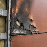
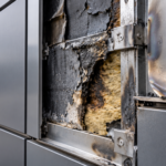
That same cavity becomes a liability in a fire event. The continuous air path that promotes drying also promotes vertical flame and hot gas travel, functioning as a chimney flue within the facade plane.
Grenfell Tower in 2017 forced a global reckoning with this physics. The fire propagation mechanism was not unique to that building; it was a predictable consequence of an uninterrupted combustible cavity running the full height of the facade.
North American code bodies accelerated revision timelines in direct response. The UK’s subsequent Hackitt Review and the resulting Building Safety Act 2022 reframed facade fire performance as a life-safety systems issue rather than a materials compliance checkbox and that philosophical shift is beginning to influence how sophisticated AHJs in North America approach plan review.
AHJs are now requesting full-assembly fire test documentation as a matter of routine, particularly on mid-rise and high-rise projects. Material-level certifications alone no longer satisfy.
A flame spread index from a small-scale Steiner tunnel test tells you nothing about how that material performs within a ventilated cavity assembly subject to a window-spill fire scenario. The Steiner tunnel, codified as ASTM E84, evaluates a material in a horizontal orientation under controlled draft conditions.
It does not replicate the vertical orientation, the cavity geometry or the thermal feedback loop present in a real facade fire. NFPA 285 is the governing full-assembly test standard for exterior wall systems containing combustible materials and the distinction between material listing and assembly listing is one that every specifier needs to internalize before schematic design.
Treating an ASTM E84 Class A rating as a proxy for NFPA 285 compliance is a category error that continues to appear in specifications and submittal packages with troubling frequency.
Understanding the Regulatory Framework: IBC, NFPA and State Amendments
IBC Chapter 14 governs exterior walls at the prescriptive level, establishing combustibility classifications and cladding attachment requirements. Chapter 26 addresses foam plastic insulation and Section 2603.5 is the provision that trips up the most projects: foam plastic insulation in exterior walls requires NFPA 285 compliance when used in combination with combustible cladding.
That requirement applies regardless of insulation thickness or cladding percentage. A project team that specifies a 1-inch polyisocyanurate layer as a thermal break under a wood rainscreen panel system and assumes the thin insulation profile exempts them from NFPA 285 is reading the code incorrectly.
The trigger is the combination of foam plastic and combustible cladding, not the insulation thickness.
The 2021 IBC Section 1402.5 tightened combustible cladding restrictions specifically for buildings with occupied floors above 40 feet. The threshold is not building height to roof; it is occupied floor elevation.
Consultants who are measuring to the parapet and concluding they are under the threshold need to re-read the section. A five-story building with a mechanical penthouse and an occupied fifth floor at 42 feet above grade is subject to Section 1402.5 regardless of what the total roof height measures.
This is not an ambiguous reading; it is the plain language of the provision.
NFPA 285:2019 is the current edition of the fire test standard. It measures vertical and lateral flame spread through the exterior wall assembly under a simulated window-spill fire condition.
The test does not evaluate the assembly in isolation; it evaluates the complete system including substrate, sheathing, air barrier, insulation, cavity geometry and cladding. Every component matters.
State amendments complicate the picture considerably. California’s Title 24 carries fire provisions that exceed IBC minimums in several occupancy categories and the California Office of the State Fire Marshal maintains its own listing program that operates in parallel with ICC-ES.
New York City’s Building Code, based on a modified 2014 IBC chassis, has its own facade inspection and fire performance requirements that diverge from the 2021 IBC in ways that catch out-of-state consultants repeatedly. Local Law 11, now operating under the Facade Inspection Safety Program, adds inspection and documentation obligations that interact with fire performance documentation in ways that are not always obvious at project outset.
Massachusetts references the 9th Edition of the Massachusetts State Building Code, which adopts the 2015 IBC base with amendments. Confirming the local adoption cycle with the AHJ at project outset is not optional; it is the first step.
Occupancy type, construction type under IBC Types I through V and building height are the three variables that determine which requirements apply. Get those three inputs wrong and every subsequent specification decision is built on a false premise.
A Type III construction mixed-use building with residential above retail sits in a very different compliance position than a Type I high-rise with the same cladding system and the specification must reflect that difference from the first issue.
How Rainscreen Cavity Design Affects Fire Behavior
Cavity geometry is a fire performance variable, not just a moisture management variable. Depth, continuity and compartmentalization each influence how rapidly flame and hot gases travel vertically within the assembly.
A 3/4-inch drained cavity and a 2-inch ventilated cavity behave differently under fire conditions and that difference must be reflected in the tested assembly configuration. The deeper cavity allows greater air volume and velocity during a fire event, which accelerates flame travel and increases the thermal exposure to the cladding material on the outboard face.
Tested assemblies specify cavity depth as a defined parameter and exceeding that depth to accommodate a thicker insulation layer or a different attachment system geometry is not a minor deviation.
Open-joint cladding systems present a higher ignition risk than closed-joint systems because the cavity is directly exposed to radiant heat and flame from adjacent fenestration. Closed-joint systems reduce direct flame impingement on the cavity interior but do not eliminate it; fire can enter at penetrations, at terminations and through the cladding material itself if it is combustible.
Open-joint wood rainscreen systems are among the most difficult assemblies to bring into NFPA 285 compliance because the combination of a combustible cladding material and direct cavity exposure creates a high flame spread potential that few tested assembly configurations have addressed successfully.
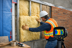
Insulation type is arguably the single most consequential material decision for assembly fire performance. Mineral wool continuous insulation is noncombustible under ASTM E136 and performs well under fire exposure without contributing to flame spread.
It also retains structural integrity at elevated temperatures, which matters for cavity geometry maintenance during a fire event. Polyisocyanurate and EPS behave entirely differently.
Both are combustible, both require NFPA 285 assembly testing when used with combustible cladding and both carry significant constraints on the assemblies in which they have been tested and listed. Polyisocyanurate has a higher ignition temperature than EPS and produces a char layer that provides some self-limiting behavior, but neither characteristic eliminates the NFPA 285 requirement or substitutes for a valid assembly listing.
NFPA 285 test protocol subjects the assembly to a window-spill fire scenario that produces both vertical flame spread up the facade and lateral spread across the cavity. The cavity geometry in the tested assembly must match the specified assembly exactly.
Widening the cavity by half an inch to accommodate a thicker insulation layer invalidates the listing. This is not a conservative interpretation; it is the explicit requirement of the test standard, which defines the tested configuration as the basis for compliance.
FM Global Property Loss Prevention Data Sheet 1-57 provides supplemental guidance on cavity compartmentalization and is worth keeping in the reference library for projects where the AHJ pushes back on cavity continuity. FM Global’s research on facade fire performance, conducted at their test facility in West Glocester, Rhode Island, has produced data on cavity fire dynamics that informs both the NFPA 285 standard and the engineering judgment frameworks that fire protection engineers use when evaluating non-standard assemblies.
Navigating NFPA 285: What Consultants Must Know About Assembly Listings
NFPA 285 tests the wall assembly as a system. This is the sentence that most specification errors trace back to ignoring.
Substituting any component, including cladding, insulation, air barrier membrane, sheathing type or fastener, can invalidate the listing entirely and require a new test. A new test costs approximately $30,000 to $50,000 and takes months to schedule and execute.
Southwest Research Institute in San Antonio and Intertek’s facility in Elmendorf, Texas are among the primary testing laboratories conducting NFPA 285 evaluations in North America and their scheduling queues during peak construction seasons can extend four to six months. Finding out during permit review that a value-engineered insulation substitution broke the assembly listing is an expensive lesson and the schedule impact of a new test cycle is typically unrecoverable on a project already in construction documents.
Manufacturers maintain tested assembly listings and publish them in their technical documentation. The consultant’s job is to verify that the proposed specification matches the listed assembly component-for-component.
That means checking fastener type, substrate species and density for wood-based sheathings, air barrier membrane brand and weight and cladding attachment geometry against the listing documentation. Rockwool’s TopRock DD and Comfortboard product lines, for example, are listed in specific densities within specific assemblies and substituting a lower-density mineral wool product from the same manufacturer does not automatically carry the listing.
The density affects both the thermal performance and the fire performance of the insulation layer and the listing documentation will specify the minimum density explicitly. This is not a task to delegate to a junior staff member without review.
When an exact listing match is not achievable, two paths exist. Deemed-to-comply provisions within the IBC allow certain prescriptive substitutions without retesting.
Engineering judgments, commonly called EJs, are the second path. An EJ is a documented technical analysis prepared by a qualified fire protection engineer, concluding that a proposed assembly deviation does not meaningfully alter fire performance relative to the tested configuration.
EJs require AHJ acceptance and not every AHJ accepts them. The City of Los Angeles Department of Building and Safety, for instance, has taken a conservative position on EJs for high-rise facade assemblies, preferring tested configurations over analytical arguments.
Confirm AHJ position on EJs before relying on one as a compliance strategy.
NFPA 285:2019 Section 5.1 defines the test specimen configuration requirements, including the minimum specimen dimensions of 17 feet wide by 25 feet tall and the specific burner configuration that simulates the window-spill fire condition. ICC Evaluation Service acceptance criteria AC235 is the document used to evaluate NFPA 285 test results for code compliance documentation; ICC-ES evaluation reports referencing AC235 are the standard format for demonstrating compliance to building departments.
When a manufacturer’s technical representative tells you their product “passes NFPA 285,” the correct follow-up question is: in which specific assembly configuration, with which specific companion components and is there an ICC-ES evaluation report documenting that result?
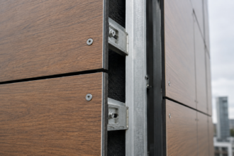
Common specification errors include substituting mineral wool at a different density than the listed assembly, changing the air barrier membrane to a different product without verifying listing compatibility and modifying the cladding attachment system geometry. A switch from a continuous Z-girt attachment to a discrete bracket system changes the cavity geometry, the thermal bridging profile and the fire performance characteristics simultaneously and a listing developed with one attachment configuration does not transfer to the other.
These errors are preventable. They require only that the specifier read the listing documentation before issuing the specification.
Material Selection Strategies for Fire-Rated Rainscreen Systems
Noncombustible cladding materials offer the most direct compliance path on buildings subject to IBC Section 1402.5. Fiber cement, terracotta, thin brick and metal panels with noncombustible cores all satisfy the combustibility requirement at the material level, which simplifies the assembly-level fire analysis considerably. Terracotta rainscreen systems from manufacturers like NBK Keramik and Shildan have well-established track records on high-rise facades precisely because the material’s inherent noncombustibility removes the cladding from the fire performance equation.
This does not eliminate the need to evaluate the full assembly if foam plastic insulation is present; Section 2603.5 still applies.
When combustible cladding is specified, which includes wood siding, fiber-reinforced polymer panels and certain composite panels, a valid NFPA 285 assembly listing is required. That determination needs to happen in schematic design, not during construction documents.
Waiting until the cladding is selected and the insulation is specified before checking listing availability is a sequencing error that creates real schedule risk. The listing search should be one of the first tasks completed after the cladding material is identified as a candidate, because the absence of a valid listing for the proposed combination is a design constraint that affects every downstream decision about insulation type, air barrier selection and cavity geometry.
Mineral wool continuous insulation is the preferred insulation choice for fire-rated rainscreen assemblies. Its noncombustible classification under ASTM E136 and its broad compatibility with tested assemblies make it the lowest-risk option from a fire compliance standpoint.
The effective R-value per inch is lower than polyisocyanurate, which creates a real tradeoff on projects with aggressive thermal performance targets. A wall assembly targeting R-20 continuous insulation will require approximately 5.5 inches of mineral wool at R-3.
7 per inch versus approximately 3.5 inches of polyisocyanurate at R-5. 7 per inch.
That 2-inch difference has real consequences for window sill depth, attachment bracket length and overall wall section thickness, particularly on infill urban sites where setback lines are tight. The fire compliance simplicity of mineral wool is substantial, but the thermal tradeoff deserves honest analysis rather than dismissal.
ACM panels require particular scrutiny. The core type determines compliance eligibility.
Fire-rated cores with an FR designation perform differently than standard polyethylene cores under fire conditions and the distinction is not academic. The Grenfell Tower cladding system used ACM panels with standard polyethylene cores, which contributed directly to the rapid fire spread.
IBC Section 1407.10 in the 2021 edition establishes specific requirements for metal composite material systems on buildings over 40 feet, including flame spread index and smoke-developed index thresholds that standard polyethylene core panels cannot meet. The FR designation itself is not uniform across manufacturers; some FR cores contain a mineral-filled polyethylene compound while others use a fire-retardant treated aluminum honeycomb and their performance under NFPA 285 conditions differs accordingly.
Specifying ACM without confirming core type and panel system listing against Section 1407.10 is a compliance failure waiting to happen.
Detailing for Fire Containment: Cavity Compartmentalization and Transition Conditions
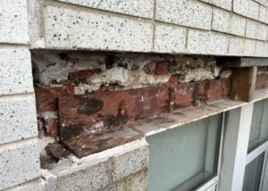
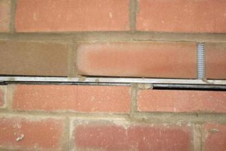
Compartmentalization of the rainscreen cavity is where design intent and field execution diverge most frequently. The concept is straightforward: horizontal fire stops at each floor line interrupt vertical flame travel through the cavity, limiting the chimney effect that makes continuous cavities so dangerous.
The execution requires coordination between the cladding attachment system, the fire stop material and the air barrier termination, all of which arrive on site from different subcontractors with different drawings. The structural steel subcontractor owns the shelf angle.
The envelope subcontractor owns the air barrier and cladding attachment. The fireproofing subcontractor owns the fire stop installation.
Without explicit coordination drawing sets that show all three systems in the same detail, the fire stop condition gets built by whoever gets there last and it rarely gets built correctly.
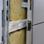
Mineral wool fire stop batts installed horizontally at floor lines are the standard approach. They must be installed at the correct density, compressed to fill the cavity completely and continuous across the full facade width without gaps at cladding attachment brackets.
A 1-inch gap at a bracket location is a 1-inch path for fire and hot gases to bypass the compartmentalization entirely. Hilti, 3M and Specified Technologies Inc.
all manufacture cavity fire stop products specifically designed to accommodate cladding attachment brackets, with pre-cut or field-cuttable profiles that maintain continuity around the bracket penetration. Specifying a generic mineral wool batt without referencing a listed cavity fire stop product and installation instruction is an incomplete specification that will produce inconsistent field results.
The four control layers, water, air, vapor and thermal, all have termination conditions at the floor line that must be coordinated with the fire stop installation. The air control layer termination at the shelf angle is already a notoriously difficult detail from a thermal bridging standpoint; adding fire stop coordination to that condition requires explicit detailing and a pre-installation conference that includes both the envelope subcontractor and the fireproofing subcontractor.
The shelf angle itself creates a thermal bridge that most energy models account for, but the interaction between the shelf angle, the air barrier termination membrane, the fire stop batt and the insulation layer at that condition is a four-way coordination problem that needs to be resolved on paper before it is resolved in the field.
Transition conditions at fenestration heads are the other high-risk location. The window-spill fire scenario in NFPA 285 specifically models flame exiting the fenestration opening and impinging on the facade above.
The cavity geometry immediately above the window head, including the presence and continuity of the air barrier return and the insulation termination, must match the tested configuration. A tested assembly that includes a 6-inch insulation return at the window head cannot be simplified to a butt termination in the field without invalidating the listing.
This detail is frequently left to field interpretation when it should be explicitly shown on the drawings, dimensioned to match the tested configuration and included in the pre-installation conference agenda.
The Specification-to-Field Gap and How to Close It
The fire code compliance work done at the specification stage fails in the field with predictable regularity. The assembly listing is verified, the components are specified correctly and then a substitution request arrives three weeks into cladding installation.
The insulation manufacturer is backordered. The air barrier product is unavailable in the required weight.
The cladding subcontractor wants to use a different attachment bracket that “works the same way. ” These are not hypothetical scenarios; they are the standard pattern on projects where the specification was written correctly but the submittal review process did not maintain the same rigor.
None of those substitutions are acceptable without a listing verification. The response to every substitution request on a fire-rated rainscreen assembly should be: provide documentation that the proposed substitution is included in a valid NFPA 285 assembly listing that matches all other specified components.
If that documentation does not exist, the substitution is not approved. The contractor’s argument that the substitute product has “equivalent” fire performance is not a basis for approval.
Equivalence under NFPA 285 is determined by testing, not by comparison of product data sheets. A submittal review checklist that includes a specific line item requiring NFPA 285 listing documentation for every fire-rated assembly component, reviewed against the original listing before approval, is a practical tool that takes fifteen minutes to create and prevents the most common field failures.
This requires that the project team, including the contractor, understand why the component-level specificity in the specification exists. A pre-construction meeting focused specifically on fire-rated assembly requirements, listing documentation and the substitution approval process is worth the time on any project subject to IBC Section 1402.5. That meeting should include the general contractor’s project manager, the envelope subcontractor’s foreman, the fireproofing subcontractor and the owner’s representative.
The meeting agenda should cover the specific assembly listing being used, the components that cannot be substituted without listing verification, the process for requesting and approving substitutions and the consequence of installing non-compliant components, which is removal and replacement at the contractor’s cost.
The AHJ is increasingly sophisticated on these issues. Building departments in major jurisdictions have added facade fire performance review to their plan check process.
Los Angeles, Chicago and Seattle have all formalized facade fire performance documentation requirements in their plan check procedures within the last three years. Submitting a specification that references NFPA 285 compliance without attaching the actual assembly listing documentation will generate comments.
Attaching the listing and confirming that the specified components match it exactly will not. Do the work before permit submission and it will not become schedule-critical during review.
The profession has the tools to get this right. NFPA 285 testing exists, listing databases are accessible and engineering judgment pathways are available for edge cases.
The failures are not technical. They are process failures, sequencing failures and the persistent assumption that fire performance review can happen after design decisions are locked.
It cannot.