- Standard manufacturer torque values for HPL panels are developed on flat-face specimens and do not account for embossed surface textures.
- Deep-texture profiles reduce effective fastener bearing area by 30 to 60 percent causing face-layer splitting before the installer detects overtightening.
- Impact drivers and undersized pilot holes amplify split risk on textured panels independent of torque setting.
- Facade consultants should require EN 438-2 surface profile data and texture-specific pull-through testing before approving embossed HPL submittals.
- Pre-installation testing on textured specimens costs far less than the labor and materials involved in a mid-project fastener audit and panel remediation.
The Crack No One Flagged Coming
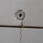
During a routine installation observation on a six-story mixed-use project in the Mid-Atlantic region, a facade consultant notices hairline radial cracks emanating from screw heads on the south elevation. Only panels with a deep wood-grain embossed texture show distress.
Smooth-face panels on the same elevation, same subframing, same crew, same day: no cracks. The contractor insists torque settings matched the manufacturer’s published specification.
They did. But no one on the submittal team had flagged that the torque value was developed for flat-face panel conditions.
The observation triggered a full fastener audit across 4,200 square feet of installed cladding.
That audit found cracking at roughly one in six fastener locations on the textured panels. The fix was not simple.
It involved partial panel removal, revised fastener scheduling and a written RFI response that no one wanted to author. The root cause was not installer error.
It was a specification gap that traveled from the manufacturer’s technical data sheet through the shop drawing review without anyone catching it.
How HPL Panels Are Manufactured and Why Surface Texture Is Not Cosmetic
HPL is a composite product: multiple layers of kraft paper saturated with phenolic resin, consolidated under heat and pressure into a dense, dimensionally stable core, then bonded to a decorative overlay that defines the visible face. The face layer is typically 0.5 to 1.
0 mm thick. It carries no design load in the structural sense.
But it is the first element to fail under localized bearing stress at a fastener location and that distinction matters enormously in the field.
Texture is not applied after pressing. It is formed during the pressing cycle itself, using structured release films or textured press plates that imprint the embossed profile directly into the face layer as the resin cures.
The result is a surface topography with measurable peaks and valleys. Surface profile depth (Rz) on deep wood-grain or stone-embossed HPL panels ranges from 0.15 mm to 0.
80 mm depending on manufacturer and finish class. That range is not cosmetic variation.
It is a geometric variable that directly controls how a screw head bears against the panel face.
EN 438-2 is the primary framework for classifying HPL surface properties, including texture characterization. No equivalent ASTM standard governs decorative face texture depth for rainscreen HPL.
That gap in domestic standards means most U. S.
-based specifiers have no standardized metric to reference when evaluating texture condition against fastener schedules. European manufacturers supplying the U.
S. market will often have EN 438-2 compliance data available on request, but that data does not automatically appear in the submittal package.
The specifier has to ask for it by name. Most do not, because the submittal checklist does not prompt the question.
Until domestic standards catch up to the product complexity that is already in the field, specifiers working with embossed HPL finishes need to treat EN 438-2 surface classification data as a required submittal item, not optional background documentation.
The Mechanics of Fastener Bearing on a Textured Surface
On a flat panel face, a countersunk or pan-head screw bearing area engages fully across the washer face or head geometry. Load distributes predictably across the contact surface.
The math is straightforward and the test data reflects real field conditions.
On a textured surface, that assumption collapses. Actual contact is limited to the high points of the embossed profile.
Effective bearing area is reduced and the remaining contact concentrates stress at discrete points beneath the screw head perimeter. The brittle phenolic face layer reaches its interlaminar tensile limit at those contact peaks before the core reaches its design bearing capacity.
The face splits before the fastener is “tight” by torque measurement. Torque is a proxy for clamp force, not a direct measure of bearing stress distribution.
Consider the geometry quantitatively. A standard 5/16-inch pan-head screw on a smooth HPL face distributes load across approximately 78 square millimeters of bearing area.
On a deep-texture surface, effective contact area may be reduced by 30 to 60 percent, concentrating equivalent force on 30 to 50 square millimeters. That stress increase can exceed the face layer’s interlaminar tensile strength before the installer’s torque wrench clicks off.
The fastener feels snug. The panel face is already damaged.
ASTM E488, which governs strength of anchors in concrete and masonry, explicitly accounts for bearing area geometry as a design variable. HPL fastener schedules almost never apply the same analytical discipline.
That contrast is not a minor oversight. It is a systematic blind spot in how rainscreen attachment gets specified and reviewed.
A structural engineer designing a concrete anchor group would never accept a published capacity value without confirming that the test geometry matched the field condition. The same standard of care should apply when a facade consultant reviews an HPL fastener schedule, but the culture of rainscreen specification has not yet demanded it consistently.
Most HPL pull-through test data is generated on flat specimens per ASTM D1761 or equivalent internal protocols. Textured panels are not a standard test condition in published technical data sheets.
The data that drives the torque specification does not reflect the surface condition that field crews are actually fastening into. A manufacturer producing both smooth and deep-embossed finishes from the same core stock will publish one pull-through value.
That value was almost certainly generated on the smooth specimen because it is easier to test and produces cleaner data. The embossed finish ships with the same number on the data sheet and no footnote flags the discrepancy.
What Manufacturer Torque Specifications Actually Cover and What They Don’t
Most HPL rainscreen manufacturers publish a single torque range, commonly 18 to 25 in-lb for #10 or #12 screws into aluminum subframing. That range derives from flat-panel pull-through and pull-out testing.
It is a legitimate value for the condition it was tested under. The problem is that submittal packages and installation guides rarely include a surface-condition modifier or a separate torque table organized by finish type.
A facade consultant reviewing shop drawings will typically find one torque value applied universally across all panel finishes on a project. The smooth-face panel and the deep wood-grain panel get the same number.
The specification does not distinguish between them and neither does the contractor’s installation checklist. On a project with a finish matrix that includes three or four panel types, that single torque value is doing work it was never designed to do.
This is not a product deficiency in the strict sense. The manufacturer tested what they tested and published what they found.
The documentation gap falls between the installation guide and the contractor’s field practice, in the space that shop drawing review is supposed to catch. It rarely does, because the reviewer is checking dimensions, anchorage spacing and material compliance.
Texture-adjusted torque is not a line item on most submittal checklists. Adding it requires the reviewer to understand the relationship between surface profile depth and bearing area reduction, which is a level of product-specific technical knowledge that general contractors and even many facade subcontractors do not carry into the review process.
IBC 2021 Section 1403.2 requires that exterior wall coverings maintain weather protection performance over the service life of the assembly. Fastener-induced face-layer splitting creates a condition where that performance degrades progressively: water infiltrates through the crack, migrates behind the face layer and accelerates delamination.
That is a code-compliance argument, not just a quality concern. AAMA 508-07 addresses attachment requirements for pressure-equalized rainscreen systems but does not differentiate by panel surface condition.
The framework exists. The texture variable simply falls outside it.
A specifier who understands that gap can write around it by requiring texture-specific testing data as a submittal condition. A specifier who does not know the gap exists will approve the submittal as submitted and move on.
Field Variables That Amplify Split Risk Beyond Torque Setting
Torque setting is the most visible variable, but it is not the only one. Pilot hole diameter is equally consequential.
Undersized pilot holes in HPL increase radial stress during screw driving independent of torque setting. Manufacturer guidance on pilot hole sizing is published but rarely enforced at the crew level and bit wear on jobsites with high panel counts compounds the problem steadily across an installation sequence.
A drill bit that is cutting clean holes at the start of a 500-panel installation may be producing undersized, ragged holes by panel 300. No quality control plan I have reviewed on an HPL project includes a bit replacement interval or a hole diameter verification check. That omission is consistent across project types and contractor experience levels.
Impact driver use is the larger field risk. Field crews frequently use impact drivers without torque-limiting clutch settings on HPL installation.
Impact drivers deliver rotational impulse loads that bypass torque-limiting behavior entirely. A single impulse event can exceed face-layer capacity before the operator perceives any resistance.
The panel cracks. The installer moves to the next fastener.
The damage is not visible at arm’s length. On a project where the QC plan does not specifically prohibit unrestricted impact driver use, this failure mode will repeat across every textured panel on the elevation before anyone identifies the pattern.
The crack is hairline at installation. It becomes a water infiltration point within the first heating and cooling cycle as thermal movement works the damaged face layer open.
Temperature at time of installation introduces a material property variable that the torque specification does not address. HPL has a coefficient of thermal expansion of approximately 3.5 x 10 to the negative fifth power per degree Fahrenheit in the plane direction.
Cold-weather installation reduces panel flexibility and increases brittleness of the face layer, compounding texture-related stress concentration at exactly the moment when the material is least tolerant of it. Most manufacturers publish a minimum installation temperature of 40 degrees Fahrenheit, but that threshold addresses adhesive and sealant performance, not face-layer brittleness under fastener bearing stress.
A crew installing deep-embossed HPL at 42 degrees Fahrenheit is technically within the published installation window. The face layer is behaving differently than it did during summer testing and the torque value on the installation guide does not account for that shift.
Specifiers working on projects with fall or winter installation schedules should require the manufacturer to confirm whether the published torque range was validated at low-temperature conditions. That question will often produce a useful conversation about what the data actually covers.
Panel orientation relative to texture grain adds a final variable. Linear wood-grain embossed profiles are directional.
Screw placement perpendicular to the grain direction intersects more texture peaks than parallel placement, creating variable split risk within the same panel face depending solely on fastener location geometry. No installation guide I have reviewed addresses this distinction.
On a facade where the panel layout runs the wood-grain texture horizontally and the fastener schedule places screws at fixed vertical intervals, the geometry of peak intersection changes at every fastener row. The installer has no way to account for that variability without explicit guidance and the specification provides none.
Reading the Submittal Package for Texture-Related Risk
A facade consultant reviewing an HPL rainscreen submittal has specific items to look for that most checklists do not include. First, identify the surface finish class for every panel type on the project and pull the Rz value from the manufacturer’s technical data sheet.
If the data sheet does not publish Rz or surface profile depth, request it directly. That number is the baseline for evaluating bearing area reduction.
An Rz value above 0.40 mm on a deep-embossed finish should trigger a request for texture-specific pull-through data before the submittal is approved. If the manufacturer cannot provide it, that absence is itself a finding that needs to be documented and resolved before installation begins.
Second, confirm whether the published torque specification references the test condition. If the technical data sheet cites ASTM D1761 pull-through testing without specifying specimen surface condition, the value applies to flat-face panels only.
Document that assumption in writing before the submittal is approved. A written record of that assumption protects the consultant if cracking appears later and creates a paper trail that supports a request for manufacturer-funded remediation.
Verbal confirmation from a manufacturer’s technical representative is not sufficient. The assumption needs to appear in the RFI response or submittal comment, not in a phone call summary that may or may not survive the project closeout.
Third, check the fastener schedule against the panel finish matrix. Projects with multiple finish types, a common condition on facades using textured accent panels against smooth field panels, need a finish-specific fastener note.
A single torque value across all finishes is a specification gap, not a conservative approach. The conservative approach is a torque table that lists each finish type by name, references the surface profile depth for that finish and assigns a torque range that accounts for bearing area reduction.
That table does not exist in most manufacturer documentation. The consultant’s job is to require it.
Finally, confirm driver type and torque-limiting equipment in the contractor’s quality control plan. “Torque-limiting driver” should appear as a required tool.
If the QC plan lists impact drivers without restriction, issue a comment before installation begins. That comment should cite the specific failure mechanism, not just reference the manufacturer’s installation guide.
A comment that explains why unrestricted impact drivers create face-layer splitting risk on embossed HPL is more likely to produce a meaningful QC revision than a comment that says “comply with manufacturer requirements.
The Audit Protocol When Cracking Is Already Present
When face-layer cracking is discovered mid-installation, the audit scope needs to be defined before remediation begins. Random sampling of 10 percent of installed fastener locations is insufficient for a failure pattern that correlates with surface finish type.
Audit by panel finish category: inspect every textured panel fastener location in the affected elevation before drawing conclusions about the smooth-face panels. A 10 percent random sample across all panel types will statistically underrepresent the textured panels if they make up less than half the total panel count, which is a common condition on projects where embossed finishes appear as accent zones.
That sampling approach will produce a false picture of the failure rate and lead to an undersized remediation scope.
Document crack geometry at each location. Radial cracks emanating from the screw head perimeter indicate bearing stress failure at the face layer.
Cracks that follow the texture grain direction suggest the embossed profile is acting as a stress riser independent of the fastener head geometry. Both patterns are relevant to remediation design but they have different implications for revised torque values.
Radial cracking points to a torque reduction and bearing area increase as the primary fix. Grain-direction cracking suggests that fastener placement relative to texture orientation needs to change, which is a more complex remediation because it may require relocating fastener positions rather than simply adjusting the driving parameters.
Remediation on installed panels typically involves backing out the cracked fasteners, enlarging the pilot hole, applying a backing washer with a larger bearing footprint and re-driving at a reduced torque. The backing washer approach distributes load across a larger area and compensates partially for the texture-related bearing area reduction.
It is not a permanent engineered solution. It is a field repair that should be documented, submitted for engineer of record review and tracked for long-term performance.
Panels where cracking has propagated beyond the immediate fastener zone, typically more than 15 mm of radial crack length, should be flagged for full replacement rather than in-place repair. A backing washer will not arrest an existing crack.
It will only prevent the crack from initiating at the repaired fastener location. If the face layer has already split across a significant area, the panel’s weather resistance is compromised regardless of what happens at the fastener head.
The Specification Has to Lead the Field
The industry will not resolve this problem through installer training alone. Crews follow what the specification and submittal require.
If the submittal approves a single torque value across all surface finishes, that is what gets installed. The fix belongs upstream.
Specifiers writing Section 07 46 00 for HPL rainscreen projects should require manufacturers to submit texture-adjusted torque data as a condition of approval for embossed finish panels. Where that data does not exist, the specification should require pre-installation pull-through testing on textured specimens per ASTM D1761 before the fastener schedule is finalized.
That requirement will generate pushback. It is still the correct call.
The alternative is discovering the problem at 4,200 square feet already installed. A pre-installation test on five or ten textured specimens costs a fraction of the labor and material involved in a partial panel removal and refastening sequence.
Framing that cost comparison explicitly in the specification narrative or in a pre-construction meeting discussion, tends to reduce resistance from contractors who would otherwise treat the testing requirement as unnecessary overhead. The specification language should also require that test specimens match the actual Rz value of the panels being installed, not a generic embossed sample from the manufacturer’s stock.
That specificity closes the last gap between the test condition and the field condition, which is where this problem has lived all along.