

Liquid Flashing Membranes at Window and Door Rough Openings: Where the Speed-of-Installation Assumption Breaks Down
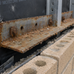
A forensic investigation on a four-story mixed-use building in the mid-Atlantic region revealed that 23 of 31 window rough openings treated with a fluid-applied flashing membrane had active water intrusion within 18 months of occupancy, despite the product carrying a 25-year manufacturer warranty and passing ASTM E2112 installation review during construction observation. Field-cut samples showed mil thickness ranging from 4 mils to 61 mils across a single sill condition and corner terminations on three openings had debonded entirely from the OSB substrate.
The product had not failed. The application had.
The Speed-and-Continuity Promise That Drove Liquid Flashing Adoption
Energy code evolution created the specification pressure. IECC 2021 Section C402.5.1.1 requires continuous air barrier treatment at fenestration rough opening transitions in commercial assemblies and the residential provisions at Section R402.
4 impose similar continuity obligations at the jamb, head and sill conditions. Self-adhered sheet flashing can satisfy these requirements, but lapped sheet membranes struggle at irregular rough openings, compound angles and CMU surrounds where substrate geometry defeats clean adhesion.
Fluid-applied products appeared to solve this. Single-component application, no lap seams and the ability to bridge minor substrate irregularities made the marketing narrative genuinely appealing to specifiers working with tight details.
IBC Chapter 14 weather-resistive barrier continuity obligations reinforced the specification rationale and fluid-applied membranes entered project specifications quickly.
The problem is that architect and specifier adoption outpaced installer familiarity. Products moved from manufacturer literature into project specifications without field mock-up requirements, without wet film thickness inspection protocols and without primer verification checkpoints.
Where liquid flashing genuinely outperforms sheet membrane is at complex geometry and irregular substrates. Where it gets specified is everywhere, including straightforward punched openings in wood-framed assemblies where a properly installed self-adhered sheet would have been faster, more forgiving and easier to inspect.
The specification-to-field gap is not a new phenomenon in building envelope work, but fluid-applied membranes have widened it in a specific way. A self-adhered sheet membrane applied at insufficient lap width is visually apparent to any inspector who knows the minimum dimension.
A fluid-applied membrane applied at 12 dry mils instead of 40 dry mils looks identical at a glance. The failure mode is invisible at the time it is created, which removes the normal feedback loop that allows field crews to self-correct.
Installers who have never used a wet film gauge have no way to know their application is deficient and inspectors who do not require thickness documentation have no way to catch it. The product’s ease of application is precisely what makes under-application so easy to miss and that dynamic does not resolve itself without explicit QA requirements written into the specification and enforced at the project level.
Substrate Incompatibility: When the Product Works and the Assembly Doesn’t
Rough opening substrates in commercial construction are not uniform and this matters more for fluid-applied membranes than for any other flashing category. OSB, LVL headers, pressure-treated sill plates, CMU block and steel stud framing with gypsum-faced sheathing each present distinct adhesion and moisture absorption profiles that directly affect long-term membrane performance.
Manufacturer adhesion testing, the data that appears in ICC-ES Evaluation Reports and on product data sheets, is conducted on clean, conditioned, laboratory-prepared substrates. Field substrates arrive wet, contaminated with form release agents, mill glaze from LVL surfaces or residual sealant from previous trades.
The gap between laboratory bond strength and field bond strength is not a minor calibration difference. It is frequently the difference between a functional air and water control layer and a membrane that peels off in the first heating season.
The most consistent failure mode I have documented is fluid-applied membrane applied over damp OSB or green pressure-treated sill plate. Moisture vapor drive from the substrate during the first seasonal cycle causes adhesion loss and blistering that is invisible at time of application and fully developed by the first winter.
The membrane looks fine at closeout. It is not fine.
Primer requirements compound this problem. Most manufacturers require primer on CMU, concrete and gypsum-faced sheathing and the primer step is routinely skipped to maintain schedule.
The consequences of omission are not visible at time of application, which is exactly why it keeps happening. Specifiers should cross-reference the approved substrate list in the manufacturer’s ICC-ES ESR against actual project substrate conditions before writing the specification, not after the product is already on site.
ASTM D1002 lap shear adhesion testing provides the baseline data, but that data only applies to the substrate conditions under which it was generated.
LVL headers present a specific and underappreciated problem. The mill glaze that forms on the surface of laminated veneer lumber during manufacturing creates a bond-inhibiting layer that is not visible to the naked eye and is not removed by standard surface cleaning.
Several manufacturer ESRs explicitly list LVL as a substrate requiring mechanical abrasion or primer before membrane application, but this requirement rarely makes it from the ESR into the project specification or the installer’s pre-installation checklist. The result is a membrane that appears fully adhered at application and begins to peel at the LVL interface within one to two seasonal cycles.
Pressure-treated sill plates introduce a related but chemically distinct problem: the preservative treatment compounds, particularly in newer generation copper azole and micronized copper formulations, can interfere with adhesion of certain acrylic-based fluid-applied products. Verifying chemical compatibility between the preservative treatment and the membrane chemistry is a step that almost never happens in the field and the manufacturer’s approved substrate list frequently does not address it with the specificity the field condition requires.
Corner Bridging Failures: Why Fluid Application Alone Is Insufficient at Inside Corners
Inside corners at rough opening jamb-to-sill and jamb-to-head transitions are the highest stress concentration points in the assembly. Differential movement between framing members, thermal cycling across the fenestration frame and seasonal shrinkage in wood framing members create tensile demand that exceeds the elongation capacity of thin fluid-applied films.
This is not a material deficiency. It is a geometry problem that requires a reinforcement solution.
Minimum dry film thickness at corners is rarely achieved without mesh reinforcement. Liquid product sags and self-levels away from inside corner geometry during application, producing thin spots precisely where thickness is most critical.
The installer applies what looks like adequate material, but surface tension and gravity redistribute the wet film before it cures, leaving the corner with a fraction of the specified dry mil thickness.
ASTM E2112-19 Section 7 addresses sill pan and corner flashing installation requirements and most manufacturer published details require a minimum 6-inch fabric or mesh reinforcement embedded in the first coat at all inside corners before the second coat is applied. This step is routinely omitted entirely.
When it is attempted, mesh is frequently laid on top of the wet coat rather than sandwiched between two coats, which provides no meaningful reinforcement and creates a disbonded fabric layer that accelerates future failure.
The distinction between the manufacturer’s published detail and what installers execute under production conditions is not subtle. It is the difference between a corner that survives thermal cycling and one that debonds within two heating seasons.
Specifiers who do not require pre-installation submittals showing the corner reinforcement sequence and inspectors who do not verify mesh embedment before second coat application, are accepting a corner detail that will fail on a schedule.
The tensile demand at inside corners is not theoretical. Wood framing in a typical commercial wood-framed building experiences seasonal moisture content swings of 6 to 10 percent between summer and winter conditions in most climate zones and the dimensional change associated with that moisture cycling generates measurable movement at rough opening corners.
A 2×6 stud at 12 percent moisture content shrinking to 8 percent moisture content loses approximately 0.08 inches across its width. Multiplied across a rough opening with multiple framing members, that cumulative movement is sufficient to stress an unreinforced fluid-applied corner film beyond its elongation capacity, particularly when the film is at the thin end of the application range.
Polyurethane-based fluid-applied products generally offer higher elongation at break than acrylic-based products, with some formulations achieving 300 percent or greater elongation per ASTM D412 testing, but elongation data published in ESRs is generated at the tested film thickness and does not apply to films applied below that thickness. A 40-mil polyurethane membrane with 300 percent elongation capacity applied at 15 mils does not perform at the published elongation value and the corner will crack on the same schedule as a lower-elongation product applied at the same deficient thickness.
Inconsistent Mil Thickness in Field Application: The Failure Mode You Cannot See After Closeout
Most fluid-applied flashing products require 30 to 60 dry mils minimum, with the specific requirement varying by product and substrate. Achieving consistent thickness by hand application with a brush, roller or trowel across a rough opening is highly skill-dependent and the skill level varies significantly across the commercial subcontractor pool currently installing these products.
Coverage rate math is where this breaks down in practice. Installers calculate material quantity by area without accounting for substrate porosity, surface texture absorption or material loss at edges.
The result is under-application that passes visual inspection because the membrane appears continuous, but fails wet film gauge verification because it is nowhere near the specified thickness. The forensic samples from the mid-Atlantic building described in the opening showed this precisely: 4 mils to 61 mils across a single sill condition, with the thin spots concentrated at the corners and at the transition from horizontal sill to vertical jamb.
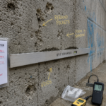
Wet film gauge use per ASTM D4414 is the straightforward QA response to this problem. The notched gauge is inexpensive and takes thirty seconds to use.
It is almost never used in field QA. Specifiers rarely require wet film thickness documentation as a submittal or inspection hold point and inspectors rarely ask for it.
ICC-ES ESR performance data, including tensile strength, elongation at break and hydrostatic resistance values, is generated at the tested thickness specified in the evaluation. A membrane applied at 15 dry mils does not perform at the values published for a 40-mil membrane, regardless of what the warranty document says.
The coverage rate problem is worth quantifying because the math makes the failure mode predictable. A fluid-applied membrane with a published coverage rate of 40 square feet per gallon at 40 dry mils applied to a rough OSB substrate will lose 15 to 25 percent of that coverage to substrate absorption, depending on OSB density and surface condition.
An installer who does not account for that absorption loss and applies at the theoretical coverage rate will consistently produce a membrane in the 28 to 34 dry mil range on OSB substrates, even when following the application instructions. On a CMU substrate without primer, absorption losses can reach 40 percent of the applied volume, producing membranes well below 25 dry mils from an application that appeared correct to the installer.
Substrate porosity correction factors are documented in some manufacturer application guides but are absent from others and the project specification rarely addresses them. The practical consequence is that installers working from coverage rate calculations alone will under-apply on porous substrates every time and the deficiency will not be apparent until the membrane is cut for forensic sampling or until water intrusion reveals it from the interior side.
Sequencing Failures: How Installation Order Turns Individual Errors Into System Failures
The correct installation sequence for a fluid-applied flashing membrane at a fenestration rough opening is: substrate preparation, primer where required, first coat application, mesh embed at all inside corners, second coat application, full cure verification, window installation, perimeter sealant and air barrier tie-in. Each step has a manufacturer-specified cure or dry time.
Production schedules routinely compress every one of them.
Window frames set before membrane achieves full cure is one of the most common sequencing failures I document. Frame fasteners driven through partially cured membrane create puncture points that are then concealed by the frame flange and perimeter sealant.
The puncture is invisible at window installation and remains invisible until water tracking through the fastener penetration appears at the interior finish, typically 12 to 24 months after occupancy.
The perimeter sealant and air barrier tie-in sequence creates a separate compounding risk. When the fluid-applied membrane at the rough opening does not receive a compatible sealant at the frame-to-membrane interface or when the WRB lapped over the membrane head flashing is not detailed to drain water away from the opening, individual application errors combine into a system that fails at multiple points simultaneously.
A single under-thickness sill, an unbridged corner and an incompatible perimeter sealant do not produce three separate failures. They produce one catastrophic failure that is difficult to attribute and expensive to remediate.
Cure time requirements deserve specific attention because they are the sequencing variable most aggressively compressed under production pressure. Most single-component acrylic fluid-applied membranes require a minimum of 24 hours at 50 degrees Fahrenheit and 50 percent relative humidity before window installation can proceed and some two-component polyurethane products require 48 to 72 hours under similar conditions.
In cold weather conditions below 40 degrees Fahrenheit, cure times for acrylic-based products extend significantly and some manufacturers prohibit application entirely below 35 degrees Fahrenheit. Production schedules on commercial projects rarely build in a 24-hour window between membrane application and window installation and the result is that windows are routinely set into partially cured membranes.
The partially cured membrane deforms under frame fastener installation rather than resisting puncture and the deformation zone around each fastener becomes a pathway for water infiltration that bypasses the membrane entirely. This failure mode is particularly difficult to remediate because the fastener penetrations are concealed under the frame flange and cannot be accessed without removing the window unit.
The remediation cost for a single window unit with fastener-related membrane punctures, including window removal, membrane repair, re-installation and interior finish repair, routinely exceeds the total cost of the original flashing installation for the entire building.
What a Defensible Specification Actually Requires
Specifying a fluid-applied flashing membrane without specifying the QA protocol that makes it perform is not a specification. It is a product selection.
The distinction matters when the claim arrives.
A defensible specification for fluid-applied flashing at fenestration rough openings requires, at minimum: a pre-installation mock-up on actual project substrates with wet film thickness documentation, primer verification as an inspection hold point on CMU and gypsum-faced sheathing substrates, mesh reinforcement at all inside corners with photographic documentation of embedment before second coat, wet film thickness readings per ASTM D4414 at sill, jamb and head conditions on a defined percentage of openings and cure time verification before window installation proceeds. These are not extraordinary requirements.
They are the minimum conditions under which the product’s published performance data actually applies.
The ICC-ES ESR for the specified product should be read in full before the specification is written, not after a failure investigation begins. The approved substrate list, primer requirements, minimum dry film thickness and corner reinforcement requirements are all documented there.
The gap between what the ESR requires and what a typical field installation delivers is where water intrusion claims are born.
The mock-up requirement deserves more specificity than it typically receives in project specifications. A mock-up on a sheet of clean OSB in a controlled environment does not replicate field conditions.
A defensible mock-up requirement specifies that the mock-up substrate match actual project substrate conditions, including moisture content, surface contamination level and temperature at time of application. It requires wet film thickness readings at a minimum of five locations per opening, including both inside corners, the sill midpoint and both jamb midpoints.
It requires photographic documentation of mesh embedment at corners before second coat application and it requires a cure time verification step before the mock-up is approved. The mock-up approval should be a contractual prerequisite to production installation, not a formality conducted after production has already begun.
When the mock-up is treated as a genuine quality gate rather than a scheduling checkbox, it consistently identifies application deficiencies that would otherwise propagate across every opening on the project.
The inspection hold point structure matters as much as the specification language. A specification that requires wet film thickness documentation but does not designate thickness verification as a hold point gives the contractor the option to self-certify and move on.
A hold point requires the inspector of record or a designated special inspector to verify the condition before the next phase of work proceeds. Designating primer application, mesh embedment and wet film thickness as hold points rather than witness points creates a contractual structure that makes deficient application visible before it is concealed by subsequent work.
The additional inspection time required to enforce these hold points on a typical commercial project is measured in hours per building, not days. The remediation cost avoided when deficiencies are caught before window installation is measured in tens of thousands of dollars per building.
Liquid flashing membranes are genuinely effective products when applied correctly. The installer training infrastructure and the project QA protocols have not kept pace with the specification adoption rate.
Until they do, the forensic caseload will keep growing and the warranty documents will keep being irrelevant.