
- A Phoenix warehouse project suffered over $340,000 in coating failures because the spec ignored tilt-up panel joint movement entirely.
- Tilt-up panels create substrate discontinuities at construction joints, lift insert pockets and reveal joints that monolithic coating specs never address.
- Elastomeric coatings lose elongation capacity rapidly in high-UV climates, dropping below 50 percent of rated performance within two to three years.
- Bond breaker tape at sealant joints and detail coats at insert pockets are proven low-cost steps that prevent the most common failure modes.
- The root cause is a documentation gap where no single party owns the interface between the sealant and coating scopes on design-build projects.
Elastomeric Coatings on Tilt-Up: Why Panel Joints Always Lose
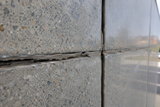
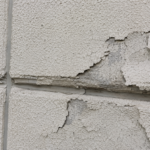
A warehouse distribution center in the Phoenix metro area, completed in late 2021, returned warranty claims within 18 months. The textured elastomeric coating had cracked through at every third-floor panel joint and was delaminating in a halo pattern around each lift insert pocket.
The coating spec had been copied from a previous project in a milder climate zone with no modification for joint geometry or movement accommodation. The GC, coating applicator and specifying architect are now in a three-party dispute over a remediation estimate exceeding $340,000. Nobody copied the wrong product.
They copied the wrong assumptions.
What Makes Tilt-Up Construction Uniquely Hostile to Monolithic Coating Systems
Most elastomeric coating systems are marketed and specified as if the substrate is a single continuous plane. Tilt-up construction is structurally the opposite.
Each panel is a discrete precast element erected and connected to adjacent panels through a system of joints, sealants and embedded hardware. The building envelope is inherently segmented and every segment boundary is a potential failure point for any coating system that treats continuity as a given.
Three discontinuity types define the problem. First, panel-to-panel construction joints are filled with sealant after erection, creating a substrate that transitions from concrete to a flexible polymer bead and back to concrete within two to three inches.
Second, lift insert pockets are cast-in voids, typically patched after erection with non-shrink grout or hydraulic cement, creating a material discontinuity in the field of the panel itself. Third, reveal joints and rustication strips used for aesthetic panel articulation create recesses and shadow lines that compound the film-thickness problem.
In IECC Climate Zone 2B, which covers the Phoenix metro, surface temperatures on west-facing concrete panels routinely swing 80 to 100 degrees Fahrenheit within a single diurnal cycle. That thermal mass drives cumulative micro-movement at every joint and pocket, day after day, for the life of the building.
The Tilt-Up Concrete Association reports that tilt-up construction accounts for approximately 15 to 16 percent of all new commercial construction starts in the United States, with the highest concentrations in Texas, Arizona, California, Colorado and Florida. Every one of those projects in high-solar-radiation zones is running this same risk.
What makes the problem harder to catch during design is that the discontinuities are not visible on the architectural elevation drawings that the coating applicator typically receives. Panel joint locations are shown on the structural drawings.
Lift insert pocket locations are shown on the erection drawings. Reveal joint geometry is shown on the architectural details.
These three drawing sets are rarely assembled into a single reference document for the coating subcontractor, which means the applicator is often working from a simplified elevation that shows a continuous surface. The field condition is discovered at the time of application, after the sealant is already cured and the erection crew has left the site.
At that point, the coating applicator has no specification guidance for how to handle the transitions and no contractual authority to stop work and request a detail. The work proceeds, the joints get coated over and the failure clock starts.
Panel size compounds the movement problem in ways that smaller precast formats do not. A typical tilt-up panel for a distribution center in the Phoenix market runs 50 to 70 feet tall and 20 to 30 feet wide, with panel weights commonly exceeding 100,000 pounds.
The sheer mass of each panel means that thermal expansion and contraction forces at the joint are substantial. A 60-foot concrete panel with a coefficient of thermal expansion of approximately 5.5 millionths per degree Fahrenheit will move roughly 0.
033 inches across its width for every 100-degree temperature swing. That movement is concentrated entirely at the joint.
The sealant is designed to absorb it. The coating bridging the joint is not.
How Elastomeric Coatings Are Supposed to Work and What the Spec Assumes
Elastomeric coatings earn their classification through elongation-at-break performance governed by ASTM D412. High-build elastomerics typically specify 100 percent elongation at minimum; premium products reach 300 to 600 percent. That elongation capacity is what allows the coating to bridge hairline cracks in the field of a panel without rupturing.
The spec assumes a continuous, planar substrate where the coating is the only layer managing micro-crack movement.
That assumption breaks at sealant interfaces. The coating is not designed to accommodate differential movement between a cured sealant bead and the concrete substrate on either side.
These are fundamentally different materials with different stiffness, different surface energy and different movement profiles. The spec language almost never addresses this distinction.
Dry film thickness is the critical variable that field application routinely gets wrong. Most elastomeric systems require 10 to 20 mils DFT to achieve their rated elongation properties.
Over a textured concrete surface, the coating builds unevenly: it pools in valleys and thins over high points. The thinnest cross-sections occur precisely at joint edges and reveal corners, which are also the highest-stress locations.
Manufacturers’ data sheets for products in the Loxon or Dymeric category commonly disclaim performance over sealant joints entirely. That disclaimer almost never survives the translation from product data sheet to project specification and the applicator never sees it.
The application rate math reinforces the problem. A product specified at 100 square feet per gallon on a smooth substrate may yield only 60 to 70 square feet per gallon on a medium sandblast texture profile because the valleys consume additional material.
An applicator pricing the job from the smooth-substrate coverage rate will underbid the material quantity and, under cost pressure, will reduce pass count to stay within budget. The result is a coating that meets the specified spread rate on paper but never achieves the minimum DFT in the field.
Third-party inspection data from tilt-up projects in the Southwest consistently shows that DFT readings at joint edges and reveal corners run 30 to 50 percent below the readings taken in the flat field of the panel. The spec does not differentiate minimum DFT requirements by location, so the applicator has no contractual obligation to build additional thickness at the highest-risk zones.
That is a specification deficiency, not an application deficiency and it belongs in the project documents before the first gallon is purchased.
The Three Failure Mechanisms: A Technical Breakdown
Sealant interface delamination is the most common failure mode and the most preventable. When an elastomeric coating is applied over a cured polyurethane or silicone sealant bead, the coating bonds to the concrete substrate on either side but achieves little to no adhesion to the sealant surface.
This creates a stress riser at both sealant edges. As the sealant cycles in tension and compression under thermal loading, it transfers shear stress into the coating film at the bond line.
The coating peels from the concrete edge rather than stretching with the sealant.
ASTM C719 governs sealant movement capability and classifies sealants by their design movement range, typically expressed as a percentage of joint width. A Class 25 sealant accommodates plus or minus 25 percent joint movement.
The problem is that nobody cross-references the C719 movement class of the specified sealant against the elongation demand the coating will experience at the joint edge. These are two separate spec sections, 07 92 00 and 09 96 00 and in practice they are written and reviewed independently.
Lift insert pocket cracking follows a different but equally predictable path. After erection, lift insert pockets are typically patched with non-shrink grout or hydraulic cement.
Both materials have coefficients of thermal expansion that differ from the parent concrete and the patch geometry creates a discrete boundary within the panel face. The coating bridges this CTE mismatch without reinforcement.
ACI 551.2R, the guide for design and construction of tilt-up concrete structures, addresses pocket patching procedures but does not specify coating compatibility requirements. Reflective cracking through the coating at pocket perimeters is the result.
It is not a defect in the coating. It is a predictable consequence of applying a continuous film over an incompatible substrate transition.
Panel joint bridging without backer rod continuity is the third mechanism. When the coating is applied continuously across a panel joint, it acts as a rigid bridge across a designed movement plane.
Joint movement within the sealant’s design range transfers shear stress into the coating film at the joint edge. Textured coatings are specifically vulnerable because the texture profile creates variable film thickness and the thinnest cross-section at the joint edge is where tensile rupture initiates first.
UV degradation compounds all three mechanisms. In high-solar-radiation climates, ASTM G154 accelerated weathering data shows that elastomeric coating films lose measurable elongation-at-break within two to three years of exposure.
The coating that passed its ASTM D412 qualification test at the factory is not the same material performing in the field in Phoenix in year three.
What the failure sequence looks like in practice is worth describing specifically. In the Phoenix warehouse case, the delamination halo around each lift insert pocket followed the pocket perimeter at a consistent offset of approximately three-quarters of an inch, which corresponds to the transition zone between the hydraulic cement patch and the parent concrete.
The crack at the panel joint was a clean tensile split running the full height of the joint, not a random map crack pattern. Both failure signatures are diagnostic.
A tensile split at the joint line means the coating was bonded to the sealant and the concrete simultaneously and had no freedom to move. A halo crack at a consistent offset from the pocket perimeter means the patch material moved independently of the parent concrete and the coating film had insufficient elongation reserve at that location to accommodate the differential.
An experienced facade consultant can identify both failure types on a site walk without any destructive investigation, which makes the diagnostic phase of a remediation project relatively straightforward. The expensive part is not identifying what failed.
It is removing and replacing a textured coating system across 180,000 square feet of panel face without damaging the underlying sealant joints.
Why Specifications Keep Getting This Wrong: The Procurement and Design Gap
Coating specs on tilt-up projects are frequently carried forward from generic CSI Division 09 master specs or from prior projects on different substrates. The tilt-up-specific joint conditions are not reflected in the spec sections for either the coating (09 96 00) or the sealants (07 92 00).
The two sections are written in isolation, reviewed in isolation and bid in isolation. The applicator responsible for the coating has no contractual relationship with the sealant installer and no obligation to coordinate sequencing or surface preparation at the joint.
The design gap is structural. Facade consultants are not always engaged on tilt-up projects, which are frequently design-build or design-assist delivery models where the structural engineer of record is the primary technical authority.
The structural engineer specifies the panel geometry, the lift insert locations and the joint widths. The architect specifies the coating.
Nobody owns the interface.
Specifying the coating system without a joint treatment detail is not a minor omission. It is the entire failure scenario.
The coating manufacturer’s representative will confirm the product is suitable for the substrate. That confirmation is technically accurate and completely useless without a joint-specific application detail that addresses bond breaker tape, DFT requirements at the joint edge and sealant compatibility.
The Phoenix warehouse project had a complete coating spec, a complete sealant spec and no detail that addressed how the two systems were supposed to coexist at the panel joint. That is a documentation failure, not a materials failure.
The procurement model on design-build tilt-up projects accelerates the documentation gap. In a typical design-build distribution center project, the structural engineer is often the engineer of record for the tilt-up panel system, the panel erector is a specialty subcontractor with its own standard details and the coating applicator is a painting subcontractor selected by the GC on unit price.
The architect in a design-assist role may produce finish specifications but rarely produces joint treatment details that coordinate across the structural, sealant and coating scopes. The result is that three separate subcontractors are each working from their own scope documents, none of which describe the interface between their work and the adjacent trade.
This is not a failure of any individual party. It is a predictable outcome of a procurement model that does not assign ownership of the interface condition.
Master spec libraries compound the problem over time. When a project completes without visible failures in the first two years, the spec gets filed as a successful reference document.
The next project in a similar building type pulls the same spec, adjusts the product names for the new manufacturer’s preference and issues it without reviewing the joint treatment requirements. The failure in Phoenix was not the first time this spec had been used.
It was the first time it had been used in a climate zone aggressive enough to produce visible failures within the warranty period. Projects in milder climates may be running the same detail deficiency and simply have not reached the failure threshold yet.
The Detail That Actually Works: Joint Treatment Before Coating Application
The correct approach is not complicated. It requires acknowledging that the panel joint is a movement plane and treating it as one before the coating is applied.
At panel-to-panel construction joints, the sealant installation should be completed and fully cured before coating begins. A bond breaker tape, typically a polyethylene-faced tape compatible with the coating system, should be applied over the cured sealant bead to prevent adhesion of the coating to the sealant face.
The coating is then applied over the tape, leaving the sealant free to move without transferring stress into the coating film. The coating bridges the tape but does not bond to it.
This is not a new concept. It is standard practice in traffic coating systems and is directly transferable to vertical elastomeric applications.
At lift insert pockets, the patch material selection matters. A polymer-modified cementitious patch with a CTE closer to the parent concrete reduces but does not eliminate the mismatch.
Applying a detail coat of full-strength elastomeric coating at the pocket perimeter before the finish coat, building DFT to a minimum of 20 mils at the pocket edge, provides the elongation reserve needed to accommodate the differential movement. This is a field labor step that costs almost nothing compared to the remediation exposure it prevents.
DFT verification at joint edges and pocket perimeters should be a hold point in the quality control plan, not an afterthought. A wet film thickness gauge costs under $50. Using it at every joint during application is not an unreasonable requirement.
The bond breaker tape specification deserves more precision than it typically receives. Tape width should be specified as a minimum of one inch wider than the sealant bead on each side, so a three-quarter-inch sealant joint should receive tape no narrower than two and three-quarter inches total.
The tape should be applied with firm hand pressure to ensure edge adhesion to the concrete, because a tape edge that lifts during coating application defeats the purpose entirely. Some applicators use a primer at the tape-to-concrete transition to ensure the tape stays down through the coating application and cure cycle.
That primer step adds approximately 15 minutes per linear foot of joint and is worth specifying explicitly. The coating spec should also require that the applicator document tape installation with photographic records before the finish coat is applied, because once the finish coat is on, there is no way to verify the tape was installed correctly without destructive investigation.
Sequencing the sealant and coating scopes requires a written coordination requirement in the project documents. The coating application should not begin until the sealant installer has completed all joints in the work area and the sealant manufacturer has confirmed full cure, which for most one-part polyurethane sealants in Phoenix summer conditions means a minimum of seven days after installation.
That sequencing requirement needs to appear in both Division 07 and Division 09 to be enforceable. If it appears only in the sealant section, the coating applicator has no contractual obligation to verify cure status before beginning work.
What Accelerated Weathering Data Actually Tells You
ASTM G154 fluorescent UV exposure testing is the standard accelerated weathering protocol for nonmetallic materials, including elastomeric coatings. The test cycles UV exposure and condensation to simulate long-term outdoor weathering.
Manufacturers use G154 data to support warranty claims and product qualification. What the data does not tell you is how a coating performs over a sealant interface or a patch material boundary under simultaneous UV degradation and cyclic mechanical stress.
That combination is exactly what a panel joint in Climate Zone 2B experiences. The coating is simultaneously losing elongation capacity from UV embrittlement and being subjected to cyclic tensile and shear loading from joint movement.
No standard accelerated weathering protocol currently evaluates this combined loading condition. ASTM G154 and ASTM D412 are run independently, on flat film specimens, without a substrate discontinuity.
The field condition is fundamentally more aggressive than the test condition.
This is not a criticism of the test standards. It is a statement about the limits of product qualification data when applied to a substrate condition the test was never designed to evaluate.
Specifiers who rely on G154 results as a proxy for joint performance are drawing a conclusion the data does not support.
The practical implication for specification writers is that no manufacturer’s published weathering data can be used to justify omitting a joint treatment detail. A product with a 10-year warranty backed by G154 cycle data has been tested on a flat, continuous film specimen.
The warranty language will contain exclusions for substrate movement, improper surface preparation and conditions outside the manufacturer’s written application instructions. Those exclusions will be invoked in any dispute involving joint failure and they will hold up because the test data genuinely does not address the joint condition.
The specifier who writes a 10-year warranty requirement into the project documents without also writing a joint treatment detail has created a warranty that cannot be honored by any product currently on the market. That is not a manufacturer problem.
It is a specification problem and it needs to be corrected before the project goes to bid, not after the claims arrive.
Field-retrieved samples from failed elastomeric coatings on tilt-up panels in Phoenix and Las Vegas consistently show elongation-at-break values below 50 percent when tested per ASTM D412 after two to three years of service exposure. Products that left the factory at 300 percent elongation are performing at less than one-sixth of their rated capacity in the field within the first third of their warranty period.
That degradation rate is not reflected in the G154 data that supported the product qualification, because the G154 protocol does not replicate the combined effect of high UV flux, elevated substrate temperatures and cyclic mechanical stress simultaneously. Specifiers working in Climate Zones 2 and 3 should treat manufacturer elongation data as a starting-point qualification threshold, not a performance guarantee for the installed system.
The Warranty Dispute Is the Wrong Place to Solve This Problem
The Phoenix warehouse remediation will likely settle somewhere between the coating manufacturer’s position (substrate was not properly prepared), the applicator’s position (the spec did not require joint treatment) and the architect’s position (the product was specified per manufacturer recommendations). All three positions have some technical merit.
None of them rebuilds the water control layer on 180,000 square feet of panel facade.
Facade consultants and specifying architects working on tilt-up projects in IECC Climate Zones 2 and 3 need to treat every panel joint as a designed movement plane in the coating spec, not just in the sealant spec. That means writing a joint treatment detail into Division 09, coordinating the sealant cure schedule with the coating application sequence and specifying DFT hold points at joint edges and insert pockets as contract requirements.
The product is not the problem. The detail is.
Specify the detail.