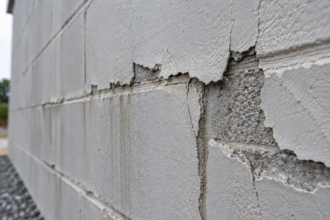
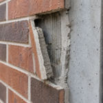



- Thin brick units on precast panels are delaminating in clusters at panel corners, even on projects that passed all mock-up reviews and mortar coverage checks.
- Differential thermal expansion between precast concrete and clay brick generates cumulative shear stress at the bond line that most specifications never calculate.
- Precast surface finish standards were written to control appearance, not to ensure bond substrate quality for adhered veneers.
- Mortar bed thickness tolerances currently permit a range wide enough that compliant installations can still be set up for premature fatigue failure.
- Four specification changes covering surface preparation, mortar performance, thickness verification and thermal movement analysis can close the system gap before failures occur.
Thin Brick on Precast: Why Bond Failure Is a System Design Problem
A forensic investigation on a four-year-old mid-rise institutional building in the Upper Midwest revealed a pattern of thin brick units delaminating in clusters at the upper corners of precast panels. The project had passed all pre-installation mock-up reviews and met specified mortar coverage requirements at time of installation.
The failure was not a workmanship anomaly. It was a system design gap that no single specification section had been written to prevent.
Why Thin Brick on Precast Is Gaining Ground (and Why That Should Concern You)
The value proposition is straightforward. Thin brick on precast eliminates field masonry labor, compresses erection schedules and consolidates trades on mid-rise commercial and institutional work.
For owners facing labor shortages and tight construction windows, the system looks like a clean solution.
The problem is that specification momentum is outpacing forensic feedback loops. The 2017 to 2020 specification surge for this assembly is now delivering projects into their first three to five year thermal cycling window.
Early failures are appearing in forensic caseloads, but they have not yet migrated into published failure rate data. That lag is dangerous.
The product itself is not the issue. Thin brick units manufactured to ASTM C1088 (Standard Specification for Thin Veneer Brick Units Made from Clay or Shale) are well-characterized, dimensionally consistent and durable.
The failure mode does not live in the unit. It lives in the assembly.
Specifiers who evaluate this system by reviewing the brick specification alone are looking at the wrong document. The risk is in the interface and the interface is where the engineering is missing.
What makes this particularly difficult to catch during design review is that the assembly looks complete on paper. Shop drawings show brick layout, mortar joint dimensions and panel geometry.
Submittals include ASTM C1088 compliance documentation for the brick units. Mock-up panels pass visual inspection and pull tests under controlled conditions.
None of those checkpoints interrogate the long-term fatigue behavior of the bond line under real thermal cycling. The system passes every gate that was designed to evaluate it and then fails on the wall four years later.
That sequence is not a coincidence. It reflects a specification framework that was built to verify components rather than predict assembly behavior.
The Mechanics of Thin Brick Adhesion to Precast Substrates
Thin brick units, typically ranging from one-half inch to one inch in thickness, rely entirely on mortar or adhesive bond to the precast substrate. There is no mechanical interlock.
There is no shelf angle providing gravity support at the unit level. There is no redundancy in the load path.
The bond interface must simultaneously transfer dead load, wind load and thermally induced shear across the full panel face. That is a demanding ask for a mortar bed that most specifications treat as a commodity item.
The mortar bed functions as the critical transition layer between two materials with fundamentally different thermal and moisture expansion coefficients. It must bond to a substrate it did not cure against, accommodate movement it was not necessarily dimensioned to absorb and maintain adhesion through hundreds of thermal cycles over a 30-year service life.
Three variables govern whether the assembly performs or fails: differential thermal movement between the precast substrate and the brick veneer, the surface condition of the precast panel at time of brick installation and the mortar bed thickness as actually installed. PCI’s Architectural Precast Concrete manual establishes surface finish classifications for precast panels, but those classifications were written to control appearance, not to optimize bond substrate quality for adhered veneers.
That distinction matters enormously and is almost never addressed at the specification stage.
What the specification typically misses is the sequence dependency of the assembly. The mortar bed is applied to a precast surface that was cast weeks or months earlier, in a shop environment, against a form that may have been treated with release agent.
By the time the thin brick installer encounters that surface, it has carbonated, possibly absorbed airborne contamination and may have been handled multiple times during transport and erection. The bond substrate that arrives on the job site is not the same surface that left the precast plant and the specification rarely accounts for that transformation.
ACI 308R-16 (Guide to External Curing of Concrete) addresses curing compound residue as a bond inhibitor, but that guidance is almost never cross-referenced in precast shop drawing submittals or thin brick installation specifications. The result is that installers are bonding to surfaces whose actual condition has never been formally evaluated against bond performance requirements.
Thermal Cycling Is Not a Background Condition: It Is the Dominant Load Case
The coefficient of thermal expansion for precast concrete runs approximately 5.5 x 10⁻⁶ per degree Fahrenheit. For clay brick, the published value per ACI 318-19 Commentary and BIA Technical Note 18A is approximately 3.3 x 10⁻⁶ per degree Fahrenheit.
That differential is modest at any single moment. Accumulated over a full thermal cycle, across a panel face measuring 10 to 12 feet, it generates shear stress at the bond line that the mortar bed must absorb entirely.
In northern U. S.
and Canadian climates, annual temperature deltas routinely exceed 120 degrees Fahrenheit. Run the math on a 12-foot panel face: the precast substrate moves roughly 0.095 inches across that annual range while the brick veneer moves approximately 0.
057 inches. The bond line must accommodate 0.038 inches of differential movement every year, in both directions, with no mechanical relief.
The failure pattern this produces is predictable. Bond fatigue concentrates at panel corners and edges where restraint conditions change abruptly.
The upper corners of panels see the highest combined thermal and wind-induced stress. This is exactly the pattern the forensic investigation described in the opening scenario documented.
The engineering gap here is structural. ASCE 7-22 Chapter 2 load combinations address wind and thermal loads at the building system level, but they do not automatically trigger bond-line shear calculations for adhered veneer assemblies in standard practice.
Most specifications treat thermal movement as a joint design issue, handled by expansion joints between panels. They do not treat it as a bond-line fatigue issue within the panel face.
Those are two different problems. Solving one does not solve the other.
The distinction between panel-level joint design and bond-line fatigue design is worth pressing further, because it is where most structural engineers and envelope consultants talk past each other. Expansion joints between panels are sized to accommodate gross panel movement relative to the building frame.
They are a structural accommodation. Bond-line fatigue is a materials problem operating at a different scale, within the panel face, where the mortar bed is cycling between tension and shear with every temperature swing.
A project can have correctly sized expansion joints at every panel boundary and still accumulate bond-line fatigue failure across the panel face interior. The two design tasks require different calculations, different material specifications and different inspection protocols.
Treating one as a proxy for the other is the specification error that sets up the failure pattern documented in the Upper Midwest case. ASTM C1583 (Standard Test Method for Tensile Strength of Concrete Surfaces) provides a field-verifiable metric for bond integrity, but it is rarely specified as an acceptance criterion for thin brick on precast assemblies.
Including it as a post-installation verification requirement, with minimum pull-off values tied to the thermal load analysis, would give inspectors an actual performance threshold rather than a visual compliance check.
Precast Surface Finish Tolerances Were Not Written With Thin Brick Bond in Mind
Precast panels are specified and accepted to PCI finish standards: smooth form finish, light sandblast, medium sandblast. These classifications control visual texture and dimensional tolerance.
They say nothing about the bond substrate requirements for a subsequently applied thin brick veneer.
Surface laitance, form release agents and low-porosity troweled finishes all reduce mechanical bond. ACI 503R-16 (Use of Epoxy Compounds with Concrete) and IBC Section 2510 both address bonding to existing concrete substrates, but neither is routinely invoked during precast shop drawing review for thin brick applications.
They should be.
The coordination gap here is a classic division-of-responsibility failure. The precast fabricator is responsible for panel finish.
The thin brick installer is responsible for mortar bond. No single party is contractually responsible for verifying that the finish delivered is appropriate for the bond required.
The fabricator meets PCI tolerances and ships the panels. The installer applies mortar to whatever surface arrives.
When bond fails four years later, both parties can point at the other.
The solution is specifying minimum surface preparation requirements by reference to ICRI Technical Guideline No. 310.2R (Selecting and Specifying Concrete Surface Preparation for Sealers, Coatings, Polymer Overlays and Concrete Repair).
For reliable thin brick bond, the precast surface should meet CSP 3 to CSP 5 per that guideline. This standard is almost never cited in precast or thin brick specification sections, which is precisely why it needs to be.
Assigning responsibility for surface verification to a named party in the contract documents is not optional. It is the only way to close the coordination gap.
Field application of ICRI CSP standards requires some translation for teams that work primarily in precast rather than repair and overlay contexts. CSP 3 corresponds to a surface with visible aggregate exposure and a texture roughly equivalent to medium sandpaper.
CSP 5 represents a more aggressive profile, similar to light scarification, with aggregate clearly fractured at the surface. A medium sandblast finish on a precast panel will typically land at CSP 3 to CSP 4, which is within the acceptable range.
A smooth form finish with residual release agent will test at CSP 1 or CSP 2 and will not support reliable long-term bond regardless of mortar selection. The practical implication is that specifying medium sandblast as the minimum precast finish for thin brick applications and requiring ICRI CSP verification before brick installation begins, eliminates the ambiguity that currently allows inadequate surfaces to pass undetected.
Some precast fabricators will flag this requirement as a cost adder. That conversation is worth having during design rather than during litigation.
Mortar Bed Thickness Tolerances Create a False Sense of Installation Compliance
Industry-standard mortar bed thickness for adhesive-set thin brick applications is typically specified at one-half inch plus or minus one-quarter inch. On paper, that looks like a reasonable tolerance.
In practice, it permits beds ranging from one-quarter inch to three-quarters inch on the same panel face and both extremes pass inspection.
Thin beds at the one-quarter inch end have insufficient volume to accommodate differential movement through plastic deformation before bond failure initiates. The mortar reaches its elastic limit early in the thermal cycling sequence and begins accumulating micro-cracking at the bond interface.
By year three or four, those micro-cracks have propagated enough to allow moisture infiltration, which accelerates freeze-thaw degradation of the bond zone and triggers the delamination clusters the forensic investigation documented.
Thick beds at the three-quarters inch end introduce their own risk. Heavier mortar beds increase dead load on the bond interface and, if the mortar mix is not properly proportioned for flexibility, can create a rigid layer that transfers differential movement directly to the brick face rather than absorbing it.
The tolerance band creates a compliance illusion: an installation can meet the specification and still be set up for premature failure at either end of the permitted range.
The fix requires tightening the tolerance and specifying mortar by performance rather than mix proportion alone. Polymer-modified mortars with documented bond strength and flexibility characteristics, tested to ANSI A118.4 (Latex Portland Cement Mortar) at minimum, provide measurably better fatigue resistance than straight Portland-lime mixes.
Requiring pre-installation verification of bed thickness uniformity across the panel face, not just spot checks at accessible locations, is best practice. It is not currently standard practice on most projects.
The verification gap is partly a tooling problem and partly a contractual one. Bed thickness on a vertical panel face is not easily measured after the brick is set.
The practical window for verification is during installation, which means the inspection protocol has to be written into the construction phase requirements rather than the closeout checklist. Specifying a maximum panel area that can be set before a thickness verification check is performed, something on the order of 25 to 30 square feet, gives the inspector a defined intervention point.
Some contractors will push back on this as a production slowdown. The response is that the alternative is a forensic investigation at year four.
Documenting bed thickness with a calibrated depth gauge and recording results by panel number and grid location also creates a project record that is genuinely useful if a bond question arises later. That documentation does not exist on most projects today because the specification never asked for it.
Writing the Specification to Close the System Gap
The three failure drivers described above are individually addressable. The problem is that no standard specification section is written to address all three simultaneously.
Division 03 covers precast concrete. Division 04 covers masonry.
Division 09 occasionally covers thin brick in adhesive-set applications. None of these sections talks to the others about the interface they share.
A specification that actually manages bond failure risk for this assembly needs to do four things. First, it must invoke ICRI 310.2R surface preparation requirements in the precast section and assign responsibility for verification to a named party before thin brick installation begins.
Second, it must specify mortar performance by reference to ANSI A118.4 or equivalent, not by generic mix proportions. Third, it must tighten mortar bed thickness tolerances and require documented thickness verification across the full panel face.
Fourth, it must require a thermal movement analysis for the specific panel geometry and climate zone, with the results used to set maximum panel face dimensions between accommodating joints.
That fourth requirement is where most projects fail to invest. A thermal movement calculation for a 12-foot precast panel in IECC Climate Zone 6 takes an engineer a few hours.
The forensic investigation that follows a bond failure takes months and costs orders of magnitude more.
The cross-division coordination problem is not solved by adding language to a single section. It requires a deliberate decision about who owns the interface.
One workable approach is to add a scope statement to the Division 03 precast section that explicitly identifies the thin brick bond substrate as a deliverable of the precast scope, not just the panel geometry and finish appearance. That language shifts the fabricator’s responsibility from producing a panel that looks correct to producing a panel that is bondable.
A corresponding statement in Division 04 or Division 09 then identifies the surface verification requirement as a precondition for installation, with a hold point in the construction schedule tied to documented ICRI CSP compliance. The hold point is the mechanism that forces the coordination to actually happen in the field rather than being assumed.
Without a contractual stop in the schedule, the installer will set brick on whatever surface is available because the schedule pressure to do so is always greater than the specification pressure not to. Writing the hold point into the contract documents is the only reliable way to change that behavior.
What the Forensic Pattern Is Telling You
The Upper Midwest case is not an outlier. It is the leading edge of a failure cohort that will become visible across the industry over the next five years as the 2017 to 2020 installation surge ages into its first major thermal cycling window.
If you have thin brick on precast in your current project portfolio, pull the specification sections and check for three things: whether ICRI 310.2R is cited anywhere, whether mortar performance is specified by test standard or by generic mix and whether a thermal movement analysis was ever performed for the panel geometry. In most cases, none of those three items will appear.
That absence is not an administrative oversight. It is the gap where bond failures are born.
The forensic pattern also carries a message for building enclosure consultants who are engaged after construction rather than during design. By the time delamination clusters are visible, the bond line has already been cycling through fatigue accumulation for years.
The visible failure is the terminal event, not the initiating one. Infrared thermography and impact sounding surveys can identify disbonded areas before full delamination occurs and both methods are documented in ASTM E2270 (Standard Practice for Periodic Inspection of Building Facades for Unsafe Conditions) as part of a facade inspection protocol.
Specifying a facade inspection at year two and year five for buildings with thin brick on precast would catch bond degradation while remediation options are still relatively contained. That inspection requirement costs a fraction of what emergency facade stabilization and unit replacement cost once full delamination is underway.
The forensic caseload building in the industry right now suggests that most project teams did not make that investment. The next generation of specifications has an opportunity to correct that.