- Published R-values for translucent panels omit framing conductance and can overstate whole-assembly thermal performance by 30 to 50 percent.
- Channel cavity condensation is predictable in Climate Zones 5 through 7 but ASHRAE 160-2016 dew point analysis is rarely performed at design phase.
- Polycarbonate expands at 3.5 times the rate of aluminum framing requiring Class 50 sealant with chemical compatibility certification at every panel-to-wall joint.
- PVC gaskets in translucent panel framing systems can fail within ten years making air leakage the primary moisture loading mechanism for the assembly.
- Four specification requirements covering whole-assembly R-value, dew point analysis, sealant compatibility and ASTM E2357 testing close the gaps that generate field failures.
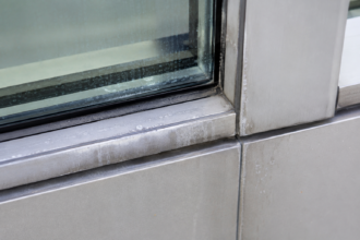
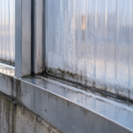
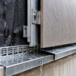
Three years after a transit authority in the upper Midwest opened a new multimodal station, the maintenance supervisor filed a formal IAQ complaint. Interior condensation had been streaking down the base channels of the polycarbonate panel facade since the first heating season.
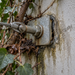
Finish staining was cosmetic. Corroding embedded fasteners were not.
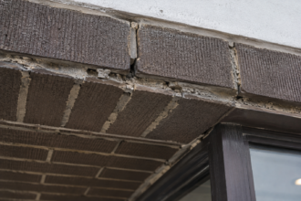
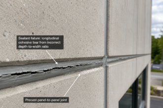
The sealant at the panel-to-CMU interface had already begun to debond along a 40-foot run and nobody could tell the owner exactly when it had started. The project had been specified to meet daylighting targets under ASHRAE 90.1-2022 Section 9.
No condensation resistance factor analysis had been performed. The channel end caps had been substituted with solid tape by the installing subcontractor.
This single callback encapsulates the three performance gaps that define the translucent panel specification problem: inadequate thermal analysis, ignored moisture dynamics and a sealant joint that was never designed to last.
Why Translucent Panel Systems Are Appearing on More Commercial Facades
Daylighting requirements under ASHRAE 90.1-2022 Section 9 have tightened the envelope tradeoff calculations that govern electric lighting power density and IES RP-5 daylighting guidance has pushed institutional designers toward daylit envelope solutions as a compliance path. The result is predictable: translucent wall panels are appearing on warehouses, transit halls, gymnasiums and institutional corridors at a rate that outpaces specifier familiarity with their performance limits.
Energy codes increasingly reward reduced electric lighting loads. That makes translucent assemblies attractive on paper.
The problem is that polycarbonate multiwall and fiberglass sandwich panels are marketed as “high-performance” without clear thermal benchmarks in product literature and the test data that does exist rarely reflects whole-assembly conditions. Specifiers frequently treat translucent panels as a glazing substitute, but they do not apply the same thermal scrutiny they would apply to a curtain wall or storefront system.
That gap between how the product is marketed and how it actually performs in a framed assembly is where callbacks originate.
The institutional building sector is particularly exposed. K-12 gymnasiums, higher education recreation centers and transit concourses all carry high interior humidity loads and long occupied hours, which amplifies the consequences of thermal and moisture underperformance.
A gymnasium that meets its daylighting target on day one but generates condensation complaints by the second heating season has not delivered a compliant building. It has delivered a deferred liability.
The specification community has not yet developed the same reflexive skepticism toward translucent panel thermal claims that it applies to window assembly U-factor marketing and manufacturers have not been compelled by market pressure to close that gap. Until whole-assembly performance data becomes a standard deliverable in product submittals, the specifier carries the burden of demanding it.
The Effective R-Value Problem: What the Data Sheets Are Not Telling You
Published center-of-cavity R-values for multiwall polycarbonate panels run from approximately R-1.8 for 16mm twin-wall to R-3. 5 for 40mm five-wall configurations.
Those numbers appear prominently in product literature. What does not appear is the whole-assembly effective R-value once aluminum framing conductance is included.
Aluminum extrusion framing creates continuous linear thermal bridges across the assembly. When framing conductance is factored into the overall thermal calculation, effective R-value routinely drops 30 to 50 percent below center-of-cavity values.
A panel spec that reads R-3.2 may deliver an effective R-value closer to R-1. 8 at the framed assembly level.
That is not a rounding error. In Climate Zone 6, ASHRAE 90.1-2022 Table 5.
5 sets maximum U-factors for opaque wall assemblies at 0.064 (approximately R-15. 6 CI).
Translucent panel assemblies are not held to that benchmark, but the interior surface temperatures they produce are governed by the same physics.
NFRC 100 provides the procedure for determining fenestration product U-factors and applies to windows, doors and skylights. It is not universally applied to opaque-adjacent translucent panel systems.
That testing vacuum means specifiers have no standardized basis for comparing whole-assembly thermal performance across product lines. Fiberglass sandwich panels with insulated cores perform meaningfully better, reaching effective R-values in the R-8 to R-14 range depending on core thickness and framing configuration.
But conflating fiberglass sandwich panels and multiwall polycarbonate in a single specification section is a persistent error that produces assemblies with unverified thermal performance and mismatched moisture dynamics.
The thermal bridge problem is compounded by framing density. A translucent panel system with horizontal intermediate extrusions at 24-inch spacing introduces a thermal bridge every two feet across the full height of the assembly.
Each extrusion conducts heat at roughly 160 BTU-in per hour per square foot per degree Fahrenheit, compared to the polycarbonate panel cavity, which conducts at a fraction of that rate. Finite element thermal modeling of these assemblies, when it is performed, consistently shows interior surface temperatures at framing members running 8 to 12 degrees Fahrenheit below the center-of-cavity surface temperature in cold climate conditions.
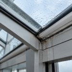
That temperature differential is enough to push framing-adjacent surfaces below the dew point of typical occupied interior air in Climate Zones 5 through 7, producing localized condensation that tracks the framing grid. Specifiers who see condensation streaking in a regular pattern on an installed translucent panel system are looking at thermal bridge condensation, not bulk infiltration.
The distinction matters because the remediation paths are completely different.
The data sheet R-value is a starting point. It is not a specification basis.
Channel Cavity Condensation: Where Moisture Accumulates and Why
Multiwall polycarbonate channels create enclosed air cavities. In humid interior environments such as gymnasiums, natatoriums, food processing facilities and transit platforms, moisture vapor migrates inward and enters those cavities.
The inner polycarbonate face is the first condensing surface.
In Climate Zones 5 through 7 during the heating season, interior surface temperatures at the inner polycarbonate face can fall well below the dew point of the interior air. ASHRAE 160-2016 provides the methodology for dew point analysis within building assemblies and that analysis should be performed at design phase for any translucent panel assembly in these climate zones.
It rarely is. Most project teams perform dew point calculations for opaque assemblies and stop there, treating the translucent panel zone as a glazing system that manages its own condensation.
It does not. Manufacturer recommendations for sealing channel ends typically specify U-channel caps with breather tape that allows drainage while limiting bulk infiltration.
In the field, installers substitute solid tape because it is faster and the distinction is not called out in the specification. Solid tape blocks drainage.
Condensate accumulates at the base channel. Over multiple heating seasons, that standing moisture promotes algae growth inside the channels.
Algae colonization is a non-recoverable performance loss. Light transmission degrades permanently.
The panel does not fail structurally, but it no longer performs the daylighting function it was specified to deliver. That outcome is entirely preventable with a specification that requires breather tape by name and includes an installer verification step at closeout.
The ASHRAE 160-2016 analysis is not a complex undertaking for a competent building enclosure consultant, but it requires project-specific inputs that are rarely assembled in a typical design workflow. The analysis needs interior design conditions, including temperature and relative humidity at peak occupancy, exterior design conditions from ASHRAE Fundamentals Chapter 14 for the project location and the thermal resistance values of each assembly layer including the framing members.
For a natatorium or food processing facility, interior relative humidity at 60 percent or above is a design condition, not an anomaly and the dew point of that air at 70 degrees Fahrenheit interior temperature is approximately 51 degrees Fahrenheit. A 16mm twin-wall polycarbonate panel with an effective R-value of R-1.8 at the framed assembly level will produce interior surface temperatures well below that threshold during any sustained cold weather period.
The condensation is not a surprise. It is a predictable outcome of an assembly that was never analyzed for the conditions it would actually experience.
Sealant Joint Incompatibility at the Translucent-to-Opaque Interface
The panel-to-adjacent-wall joint is the highest-risk detail in a translucent panel facade. Polycarbonate has a coefficient of thermal expansion of approximately 6.75 x 10⁻⁵ in/in/°F.
Aluminum runs approximately 1.3 x 10⁻⁵ in/in/°F. CMU and precast concrete are lower still.
That differential means a translucent panel assembly moves at roughly 3.5 times the rate of its aluminum framing and at a significantly higher multiple relative to adjacent masonry or precast. Over a 10-foot panel run with a 100°F seasonal temperature swing, that differential produces joint cycling that exceeds the elongation limits of standard silicone sealants specified to ASTM C920 Type S, Grade NS, Class 25.
This joint requires a Class 50 sealant at minimum and the sealant must be chemically compatible with polycarbonate. That compatibility list is narrow.
Most solvent-based sealants and certain silicone formulations attack polycarbonate, causing stress crazing at the joint edge. Manufacturer-approved sealant lists exist but are rarely incorporated into generic specification sections.
The specifier writes “silicone sealant per ASTM C920” and the installer picks whatever is on the truck.
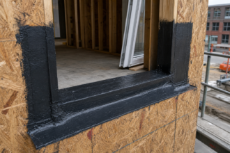
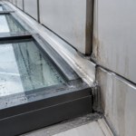
The transition from translucent panel system to opaque wall assembly also creates a discontinuity in the air barrier plane that is almost never detailed explicitly in construction documents. The four control layers (water, air, vapor and thermal) must each be addressed at this transition.
Field-applied sealant at this joint is frequently the only line of defense against bulk water infiltration. When it fails, typically within five to seven years on high-movement joints that were underspecified, water tracks into the framing cavity undetected.
By the time interior symptoms appear, fastener corrosion is already underway.
The stress crazing failure mode deserves particular attention because it is frequently misread in the field. When a polycarbonate panel develops fine surface cracking at the sealant joint within the first two to three years of service, the typical field diagnosis is UV degradation or installation damage.
The actual cause is chemical attack from an incompatible sealant and the craze pattern is concentrated at the joint edge precisely because that is where sealant contact is continuous. Once crazing initiates, it propagates under thermal cycling stress.
The joint edge becomes a water infiltration pathway even before the sealant itself debonds. Specifying sealant by ASTM C920 Class 50 without also requiring manufacturer chemical compatibility certification for the specific panel substrate leaves the assembly exposed to this failure mode regardless of how carefully the sealant is installed.
The compatibility requirement is a one-line addition to the specification. The callback it prevents can run to six figures in remediation costs on a mid-size facade.
Air Barrier Continuity Failures Specific to Translucent Panel Framing Systems
Translucent panel systems use proprietary aluminum extrusion framing. That framing is rarely tested as a complete air barrier assembly.
Air leakage performance data, when it exists, covers the panel unit itself under laboratory conditions. It does not cover the framed system as installed, including gasketed connections, panel-to-extrusion interfaces and termination conditions at the perimeter.
ASTM E2357 is the standard for air barrier assembly testing and is the appropriate requirement for translucent panel systems in commercial applications. It is routine in curtain wall specifications.
It is seldom required in translucent panel specifications. That asymmetry is a specification failure, not a product failure.
Gasketed connections between panel and extrusion degrade with UV exposure and thermal cycling. Most gasket materials in translucent panel systems are EPDM or PVC.
PVC gaskets in particular harden and lose compression set within ten years in exposed southern or high-altitude installations. Once the gasket fails, the framing extrusion becomes an air leakage pathway.
Air leakage transports orders of magnitude more moisture than vapor diffusion, so a degraded gasket in Climate Zone 5 during winter is not a minor performance issue. It is the primary moisture loading mechanism for the assembly.
Specifying ASTM E2357 testing for the framed translucent panel assembly, requiring gasket material certification and specifying a maximum air leakage rate at the assembly level rather than the unit level closes this gap. It also creates a basis for field verification that does not currently exist on most projects.
The practical consequence of omitting assembly-level air leakage requirements becomes visible in whole-building blower door testing, which is increasingly required under ASHRAE 90.1-2022 and IgCC compliance paths. When a building with a translucent panel facade fails its blower door test, the diagnostic process of isolating the leakage source is time-consuming and expensive.
Translucent panel perimeter conditions are frequently identified as significant contributors, but by that point the system is fully installed and remediation options are limited to field-applied sealant at accessible joints. That is a poor substitute for a tested assembly.
EPDM gaskets, specified by durometer and compression set requirements in accordance with ASTM D2240 and ASTM D395 respectively, maintain their sealing performance significantly longer than PVC alternatives in high-UV and high-thermal-cycling environments. The specification cost of requiring EPDM over PVC is negligible.
The service life difference in a south-facing or high-altitude installation can exceed 15 years of functional gasket performance. Requiring gasket material certification as a submittal item, rather than leaving material selection to the manufacturer’s standard offering, is the mechanism that makes that requirement enforceable in the field.
Writing the Specification Section That Closes These Gaps
Most translucent panel specifications live in CSI MasterFormat Division 08 alongside glazing systems, which is defensible from a product category standpoint but dangerous from a performance standpoint. The thermal, moisture and air barrier requirements that apply to these assemblies belong in the specification regardless of where the section sits.
Four items belong in every translucent panel specification for Climate Zones 5 through 7. First, require whole-assembly effective R-value documentation that includes framing conductance, not center-of-cavity values. Second, require dew point analysis per ASHRAE 160-2016 for the proposed assembly configuration at the project’s design conditions.
Third, specify sealant at the translucent-to-opaque interface by ASTM C920 Class 50 and require chemical compatibility certification from the panel manufacturer. Fourth, require ASTM E2357 air barrier assembly testing or require the manufacturer to provide tested assembly air leakage data at the system level.
None of these requirements are exotic. All of them are standard practice for curtain wall and storefront specifications.
The translucent panel market has simply not been held to the same standard and the result is a generation of assemblies that meet daylighting targets on day one and generate moisture callbacks by year three. The specification is the intervention point.
Use it.
The submittal requirements that support these four items are equally important and are frequently omitted from Division 08 translucent panel sections. Whole-assembly thermal documentation should require a calculation of record signed by the manufacturer’s technical representative, not a product data sheet excerpt.
The ASHRAE 160-2016 dew point analysis should be performed by the specifier of record or a building enclosure consultant using project-specific design conditions, not a generic climate zone assumption. Sealant chemical compatibility certification should require a written statement from the panel manufacturer identifying approved sealant products by manufacturer name and product designation, not a generic reference to “manufacturer-approved sealants.
” ASTM E2357 test reports should require identification of the specific framing configuration tested, because a test report for a 24-inch module spacing does not cover a 48-inch module spacing without additional analysis. Each of these submittal requirements takes one line to write.
Each one closes a gap that has produced documented field failures on completed projects. The specification section that includes all four is longer than the generic Division 08 translucent panel section that most offices use as a starting template.
It is also the one that does not generate a call from the maintenance supervisor three years after substantial completion.