
Fiber Cement Panel Rainscreen Systems in Commercial Facades: Fastener Pull-Through Limits, Joint Sealant Compatibility and Where the Moisture Cycling Assumption Creates Long-Term Attachment Failure
A facade consultant is called to a seven-story mixed-use building in the mid-Atlantic region during year six of occupancy. The owner reports “cosmetic cracking” near panel edges.
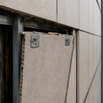
On site, the consultant finds not surface crazing but through-fractures radiating from every visible fastener head on the south and west elevations. The panels haven’t failed aesthetically.
They’ve failed structurally at the attachment zone and the substrate behind them has been cycling moisture for years. The specification was a direct lift from a residential product data sheet, scaled up without a single pull-through calculation.
This is not an unusual case. It is, in my experience, a representative one.
Why Fiber Cement Became the Default Mid-Rise Cladding Choice and What Got Left Behind in the Transition
Fiber cement occupies an installed cost range of roughly $80 to $150 per square foot on mid-rise commercial facades, which positions it well below terracotta and aluminum composite panel systems when value engineering pressure arrives late in design development. According to Dodge Construction Network data, fiber cement cladding was specified in approximately 34% of mid-rise commercial projects in 2022 and 2023, a figure that reflects both its cost position and the breadth of product lines manufacturers have pushed across residential and commercial sectors simultaneously.
That cross-sector marketing is where the specification problem originates. Manufacturers publish product data sheets that serve both a custom homebuilder and a facade engineer on a 12-story mixed-use project and the performance tier differentiation between those two use cases is rarely explicit in the literature.
Design-assist and value engineering processes accelerate the problem. A metal panel system gets specified through schematic design, the contractor proposes fiber cement as a substitution during design development, the architect approves the color and texture match and the attachment engineering never gets re-examined.
The aesthetic review and the structural performance review are treated as the same review. They are not.
What makes this substitution pathway particularly consequential is the point in the project schedule at which it typically occurs. By the time a fiber cement substitution arrives as a value engineering proposal, the facade engineer of record has often been released from the project or reduced to a review-only role.
The contractor’s submittal package includes the manufacturer’s standard installation guide, which references residential-scale fastener patterns and low-rise wind pressure assumptions and no one in the approval chain has the explicit contractual responsibility to flag the mismatch. The architect reviews for color, texture and joint alignment.
The structural engineer of record reviews for gravity and lateral loads on the primary structure, not for cladding component attachment. The facade engineer, if still engaged, may review the submittal for general conformance without running independent pull-through calculations for the specific building height, exposure category and corner zone geometry.
The result is a facade that passes every submittal review and fails in the field within a decade.
The manufacturer’s role in this dynamic deserves direct examination. Several major fiber cement manufacturers, including James Hardie, Nichiha and Allura, produce separate commercial-grade technical documentation that includes higher-density panel formulations, thicker nominal dimensions and fastener pattern tables developed against ASCE 7 commercial wind pressure assumptions.
That documentation exists. It is not always what gets submitted.
When a contractor sources product data sheets from a manufacturer’s general download portal rather than requesting the commercial technical package specifically, the residential-grade documentation is what lands in the submittal. Specifiers who want the correct documentation need to name it explicitly in the specification section, not assume the submittal process will self-correct.
Fiber Cement Panel Anatomy and the Tolerance Variables Specifiers Routinely Ignore
Fiber cement panels are not a single material. The Portland cement-to-cellulose fiber ratio varies meaningfully between manufacturers and even between product lines within the same manufacturer’s catalog.
Higher cellulose content increases flexibility but reduces edge strength and increases hygroscopic movement. Higher cement content increases density and brittleness.
Both variables directly affect how a panel behaves at the fastener zone under load.
ASTM C1186, the Standard Specification for Flat Fiber Cement Sheets, permits a thickness variation of plus or minus 10% in Type A panels. On a 5/16-inch nominal panel, that tolerance range spans from approximately 0.281 to 0.
344 inches. On a 3/8-inch nominal panel, it spans from 0.338 to 0.
413 inches. The pull-through capacity published in a manufacturer’s load table is calculated for the nominal thickness.
A panel at the low end of the tolerance range delivers meaningfully less bearing area at the fastener head and that reduction compounds when the panel has also been field-cut to accommodate an opening or a substrate framing condition that doesn’t align with the panel module.
ASTM C1186 also classifies fiber cement sheets by type and grade. Type A covers flat sheets for general use; Type B covers sheets intended for use in higher-humidity conditions.
Grade I panels are intended for non-structural applications; Grade II panels carry structural performance requirements. The distinction between Grade I and Grade II is directly relevant to rainscreen attachment engineering and specifications that reference only the standard number without specifying the grade leave the contractor free to supply the lower-performing product.
In practice, Grade I material shows up on commercial facades regularly because the specification language didn’t close that door.
Manufacturer-published minimum edge distances run typically from 3/4 inch to 1 inch from the panel edge. Field cuts routinely violate those minimums.
The crew cutting panels to fit around a window rough opening or a reveal condition at a floor line is not consulting the technical data sheet. That’s the specification-to-field gap that produces the fracture patterns the consultant finds in year six.
A practical mitigation is to require that field-cut panels within 12 inches of any opening or termination condition be reviewed by the installer foreman before installation, with minimum edge distance compliance documented on the cut list. That requirement adds approximately two hours of administrative time per floor per elevation.
It is not a burden that any competent contractor should resist and resistance to it is itself a quality signal worth noting during preconstruction.
Concealed clip systems do not eliminate pull-through risk. They transfer it to the panel back-kerf or slot, where the bearing geometry is even less forgiving than a face-fastened condition.
The kerf depth and width tolerances in concealed clip systems are tighter than the fastener hole tolerances in face-fastened systems and field fabrication of kerfs with undersized or worn router bits produces bearing surfaces that deviate significantly from the manufacturer’s tested geometry. Specifiers who select concealed clip systems for aesthetic reasons need to require kerf dimension verification as a quality control item, not assume that the clip hardware controls the outcome.

Fastener Pull-Through Capacity: The Calculation Most Specifications Never Include
Pull-through failure and pull-out failure are not the same mode. Pull-through is a panel material failure: the fastener head passes through the panel face under tensile load perpendicular to the panel plane.
Pull-out is a substrate failure: the fastener withdraws from the framing or sheathing. Specifiers conflate these routinely and the conflation matters because the governing failure mode on a fiber cement rainscreen assembly under wind suction is almost always pull-through, not pull-out.
Manufacturer pull-through load tables publish values for a specific panel thickness, a specific fastener head diameter and a specific substrate type under static load. None of those published values account for cyclic fatigue.
A panel on a south or west elevation in IECC Climate Zone 4A or 5A will experience thousands of wind load cycles over its service life and pull-through capacity under repeated loading degrades measurably below the static value. No current ASTM standard for fiber cement panels requires cyclic pull-through testing as a product qualification criterion.
That gap is a serious problem that the industry has not addressed.
The fastener head diameter variable deserves more attention than it typically receives in specification language. A No.
10 screw with a standard flat head delivers a bearing diameter of approximately 0.438 inches against the panel face. The same No.
10 screw with a large-diameter washer head delivers a bearing diameter of 0.625 inches or more, depending on the washer geometry. The difference in bearing area between those two configurations is approximately 100%, which translates directly to pull-through capacity.
Manufacturer load tables that specify fastener type by gauge number without specifying head geometry leave that 100% capacity variable uncontrolled. Specifiers should require fastener submittals that include head diameter dimensions, not just gauge and length and should verify that the submitted fastener matches the geometry assumed in the load table being used for design.
ASCE 7-22 Chapter 30 governs components and cladding wind pressure design. Section 30.3 applies to low-rise buildings; Section 30.
5 applies to mid-rise buildings in the 40- to 75-foot height range. The distinction matters because the corner zone pressure coefficients, expressed as GCp values, can reach negative 2.8 to negative 3.
5 in Exposure Category C for mid-rise buildings. Residential product data sheets are typically developed against low-rise assumptions where corner zone GCp values are substantially lower.
Applying those tables to a seven-story building in an open suburban exposure underestimates corner zone demand by a factor of 1.5 to 2. 0.
The fastener pattern that works at the field zone of a residential installation fails at the corner zone of a commercial facade. This is not a conservative interpretation.
It is what the load tables show when you actually run the numbers.
The zone boundary geometry under ASCE 7-22 Figure 30.5-1 defines corner zones as extending inward from the building corner a distance equal to the lesser of 10% of the least horizontal dimension or 40% of the mean roof height, with a minimum of 4% of the least horizontal dimension. On a seven-story building with a 60-foot plan dimension and a mean roof height of 75 feet, that corner zone extends approximately 6 feet from each corner.
Every fastener within that 6-foot band needs to be designed against the corner zone GCp, not the field zone GCp. Specifications that show a single fastener pattern across the entire elevation, without differentiating field zone from corner zone, are incomplete regardless of what load standard they reference.
Moisture-Driven Dimensional Movement: The Cycling Assumption That Breaks Attachments Over Time
Fiber cement’s published linear movement coefficient runs from 0.02 to 0. 04 inches per foot across a 30% relative humidity swing, depending on the product formulation.
Across a 10-foot panel run, that produces between 0.24 and 0. 48 inches of total movement.
Specifiers who acknowledge this number at all tend to treat it as a symmetric oscillation, which it is not.
Fiber cement absorbs moisture and expands relatively quickly, on a timescale of hours to days following a rain event or humidity spike. It releases moisture and contracts slowly, over weeks.
That asymmetry creates a ratcheting stress condition at fixed fastener points rather than a balanced oscillation. The panel wants to stay expanded.
The fastener resists contraction. Each cycle loads the fastener hole in bearing and each cycle slightly enlarges the hole geometry.
After 50 to 100 moisture cycles, which is achievable within two to three years in a humid climate zone like IECC Zone 4A or the Gulf Coast Zone 2A, the fastener hole no longer matches the bearing area assumed in the original pull-through calculation. The effective bearing area has decreased.
The pull-through capacity has decreased with it. The wind load demand has not changed.
This is the mechanism that produces the year-five to year-ten failure window that facade consultants see repeatedly.
The ratcheting mechanism is not hypothetical. Researchers at the Oak Ridge National Laboratory documented hygroscopic ratcheting in wood-based panel products under cyclic humidity exposure as early as 2003 and the same physical mechanism applies to cellulose-reinforced cement composites.
The fiber cement industry has not produced equivalent long-term cyclic testing data for its commercial panel products, which means specifiers are working without a published degradation curve. The conservative engineering response to that data gap is to apply a capacity reduction factor to published static pull-through values when designing for long-term service in humid climates.
A reduction factor of 0.75 applied to static pull-through capacity is a reasonable starting point based on analogous cyclic degradation data from wood composite panels, though that figure is a professional judgment, not a code-prescribed value. Specifiers who want a defensible basis for that reduction should request it explicitly from the manufacturer as a condition of product approval.
Rainscreen cavity ventilation design directly affects the amplitude of these moisture cycles. A cavity that drains and ventilates adequately allows the panel to dry between events, reducing cycle amplitude.
A cavity with inadequate drainage plane detailing, non-compliant with ASHRAE 90.1-2022 requirements for continuous drainage, traps moisture and increases cycle amplitude. James Hardie and Nichiha both publish movement coefficient data in their technical documentation; specifiers should pull those values and run the arithmetic before finalizing fastener patterns and joint widths.
ASTM E2112-19 Section 7 establishes the baseline sealant joint movement standard for adjacent assembly joints and the same movement accommodation logic applies here.
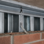
The cavity depth variable interacts with ventilation performance in ways that specifications frequently underspecify. A 3/4-inch cavity behind a fiber cement panel on a metal stud framing system with continuous insulation provides adequate drainage but marginal ventilation in low-wind conditions.
A 1.5-inch cavity with open-joint ventilation at the base and a screened vent at the top of each story provides meaningfully better drying performance. The International Building Code Section 1404.2 establishes minimum requirements for drainage plane continuity but does not prescribe cavity depth for ventilation performance.
ASHRAE 90.1-2022 addresses continuous insulation requirements that affect cavity geometry but does not address ventilation adequacy directly. The gap between code minimums and performance-adequate cavity design is where moisture accumulates and where the ratcheting failure mechanism accelerates.
Joint Sealant Compatibility and the Movement Capacity Mismatch
Sealant joint sizing for fiber cement assemblies fails at the specification stage more often than at the installation stage. ASTM C1193, the Guide for Use of Joint Sealants, requires joint width to be sized for the anticipated movement at the published movement capacity of the selected sealant.
Most fiber cement specifications default to a 3/8-inch joint with a sealant rated for plus or minus 25% movement capacity. That gives you 0.094 inches of total allowable movement at the joint.
For a panel with a 0.04-inch-per-foot movement coefficient across a 24-inch panel width in a climate with significant humidity swings, that joint is undersized before the building is two years old.
The arithmetic here is straightforward and is rarely performed. A 24-inch-wide panel with a movement coefficient of 0.04 inches per foot produces 0.
08 inches of movement across its width under a 30% relative humidity swing. A 3/8-inch joint with a plus or minus 25% sealant accommodates 0.094 inches of total movement, which appears adequate by a margin of 0.
014 inches. That margin disappears when the panel is at the low end of the ASTM C1186 thickness tolerance, when the installed joint width is at the low end of field workmanship tolerance and when the building is located in a climate zone with humidity swings exceeding 30%.
IECC Climate Zone 4A, which covers most of the mid-Atlantic and upper South, routinely produces seasonal humidity swings of 40% to 50% between summer peak and winter low. At a 45% humidity swing, the same 24-inch panel produces 0.12 inches of movement, which exceeds the 0.
094-inch capacity of the specified joint by 28%. The joint fails in tension at the panel edge and it fails within the first two to three seasonal cycles.
The substrate compatibility issue compounds the problem. Fiber cement panel edges are alkaline, with pH values running from 11 to 13 at freshly cut surfaces.
Not all silicone or polyurethane sealants maintain long-term adhesion to high-pH substrates. Adhesion failure at the panel edge is a separate failure mode from cohesive sealant failure and it produces water intrusion at the joint regardless of whether the sealant bead itself remains intact.
The water control layer behind the panel takes the load when the sealant joint fails, which is exactly the condition that produces the substrate moisture cycling described in the opening case. Specifiers need to require pH-compatibility documentation from the sealant manufacturer as a submittal item, not as an afterthought.
Dow, Sika and Tremco all produce sealant products with documented alkaline substrate compatibility and each publishes adhesion test data against cementitious substrates in their technical data sheets. The specifier’s job is to require that documentation for the specific fiber cement product being installed, not for a generic cementitious substrate.
Panel surface treatments, factory-applied primers and cut-edge conditions all affect adhesion performance independently of bulk pH and a sealant that performs well against a factory-finished panel face may perform poorly against a field-cut edge where the surface treatment has been removed. Requiring adhesion test data against both factory-finished and field-cut panel surfaces as separate submittal items closes that gap.
It is a one-page submittal request that takes a manufacturer’s technical representative approximately 30 minutes to fulfill. The failure to require it is a specification omission, not a resource constraint.
The Specification Practice That Would Actually Prevent These Failures
The failure pattern described throughout this article is not a material indictment of fiber cement. It is an indictment of a specification workflow that