- Concealed horizontal liner pan joints create capillary traps that keep zinc-coated steel wet far longer than coating specifications assume.
- Standard G90 coating weight designations are selected for free-air exposure and are not adequate for geometry-induced moisture entrapment at trapped laps.
- Galvalume sheet is explicitly warned against by its producers for cut-edge-exposed moisture-trapping conditions yet routinely appears in liner pan submittals.
- Stainless fasteners in zinc-coated concealed joints accelerate zinc depletion through galvanic action that standard MasterSpec sections do not address.
- Specifiers must require coating process identification, minimum drainage gaps at horizontal laps and fastener isolation details before the submittal stage.
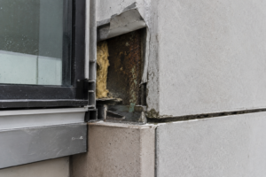
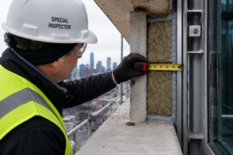
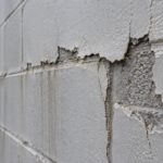
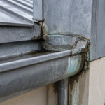
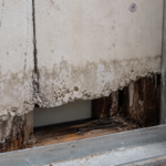
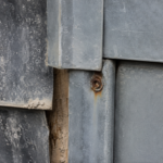
A facade contractor on a mid-rise commercial project in the Pacific Northwest removes a concealed horizontal liner pan joint during a warranty inspection eighteen months after substantial completion and finds red rust bleeding through the zinc coating at every cut edge and fastener penetration along the trapped lap. The coating manufacturer’s technical representative arrives on site, photographs the assembly geometry and denies the claim within two weeks, citing moisture entrapment as an installation condition outside the product’s intended use.
The dispute that follows is not unusual. It is becoming a pattern.
How Concealed Liner Pan Assemblies Are Designed to Work
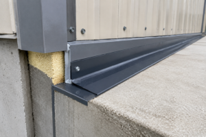
Liner pan rainscreen assemblies consist of discrete formed steel pans installed in horizontal courses with concealed vertical and horizontal joints, typically back-ventilated against a continuous substrate or structural backup. The design premise is straightforward: the outer pan layer intercepts bulk water while the drained cavity behind it handles whatever infiltrates the rainscreen gap.
Moisture that enters the cavity is meant to drain freely to weep points at the base of each course and evaporate through the ventilated air space. That two-stage drainage and drying logic is what allows designers to eliminate exposed sealant lines from the facade.
The horizontal joint is where the aesthetic promise of the system lives. Overlapping or interlocking pan edges conceal fasteners and create the clean shadow lines architects are specifying on commercial facades from Seattle to Atlanta.
That visual cleanliness is also driving the shift toward zinc-coated steel substrates as a cost-competitive alternative to aluminum extrusions or stainless sheet, particularly on mid-rise projects where facade budgets are under pressure. A formed steel liner pan can cost thirty to forty percent less than a comparable aluminum extrusion system at the fabrication stage and that delta is large enough to move a project decision without a corresponding analysis of long-term corrosion risk.
The back-ventilated cavity depth matters to system performance in ways the design drawings rarely capture. ASHRAE 90.1 and the International Energy Conservation Code do not prescribe minimum cavity depths for metal rainscreen assemblies and fabricators routinely propose cavity depths of three-quarters of an inch to one inch to minimize wall assembly thickness.
At those depths, airflow through the cavity is laminar and slow. Drying rates for moisture that reaches the back of the pan are measured in days, not hours, under typical Pacific Northwest or Great Lakes climate conditions.
The drainage and drying logic that justifies eliminating sealant depends on cavity geometry that the specification frequently does not enforce.
No installation standard equivalent to ASTM C1780 exists for metal liner pan assemblies. ASTM C1780 governs exterior dimension stone anchor installation with explicit requirements for drainage, fastener compatibility and joint geometry.
The absence of a parallel standard for metal liner pans leaves fabricators, installers and specifiers without a shared reference point for what a compliant joint condition actually looks like. That absence is not an oversight waiting to be corrected by a standards committee.
It is an active liability condition on every project that specifies these assemblies today.
What “Zinc-Coated Steel” Actually Means on the Submittal
“Zinc-coated steel” on a submittal can mean three meaningfully different products. Hot-dip galvanized sheet under ASTM A653/A653M, electrogalvanized sheet under ASTM A879 and Galvalume (aluminum-zinc alloy) sheet under ASTM A792 all appear under that description and their corrosion performance profiles diverge significantly in moisture-trapping conditions.
Coating weight designations under ASTM A653 run from G60 through G115 and above. A G90 designation means 0.90 oz/ft² of zinc total across both sides, which translates to approximately 0.
76 mils of zinc per side. That is not a thick coating.
It is adequate for free-air exterior exposure in moderate environments. It is not adequate for sustained electrolyte contact at a cut edge in a geometry that prevents drying.
G115 doubles the zinc reserve on a per-side basis relative to G60 and extends the time-to-corrosion at a cut edge meaningfully, but it does not change the underlying geometry problem. A thicker coating delays the failure.
It does not prevent it if the joint never dries.
The submittal gap is a real problem. Liner pan fabricators routinely specify minimum coating weight without identifying the deposition process, leaving the specifier unable to evaluate actual corrosion reserve or coating adhesion characteristics.
G90 hot-dip galvanized and G90 electrogalvanized carry the same designation but different microstructures, different edge coverage characteristics and different performance in cyclic wet/dry conditions. Hot-dip galvanized sheet develops a zinc-iron alloy layer at the steel interface during the immersion process that electrogalvanized sheet does not.
That alloy layer affects adhesion under mechanical deformation during forming and affects the coating’s response to cyclic stress at bend radii, which is exactly where liner pan flanges are formed and where coating continuity is most likely to be compromised before the panel ever reaches the wall.
Galvalume deserves specific attention because it is increasingly specified on the basis of its superior barrier protection on flat sheet. That performance advantage is real.
It is also explicitly qualified by steel producers: BIEC International and legacy Bethlehem Steel technical guidance both warn against using Galvalume in cut-edge-exposed, moisture-trapping conditions. The aluminum-zinc alloy does not provide the same sacrificial galvanic protection at sheared edges that pure zinc coatings do.
Specify Galvalume for a liner pan assembly with concealed trapped joints and you are selecting a product whose producers have told you not to use it that way. That warning appears in product technical bulletins that are publicly available and that coating manufacturers will cite in warranty denial correspondence.
The specifier who approves a Galvalume submittal for a concealed-joint liner pan assembly without reading those bulletins has not performed a defensible submittal review.
Electrogalvanized sheet under ASTM A879 is the third product that appears under the “zinc-coated steel” description and the one least suited to exterior moisture-trapping conditions. Electrogalvanized coatings are thin by design, typically in the range of 0.1 to 0.
4 mils per side and they are applied primarily for paint adhesion and indoor corrosion resistance rather than exterior durability. A liner pan fabricator substituting electrogalvanized sheet for hot-dip galvanized to reduce material cost is making a change that the submittal description “zinc-coated steel” will not catch unless the specification requires explicit process identification.
The Trapped Joint Geometry: Why This Detail Is the Problem
The concealed horizontal lap joint in a liner pan assembly creates a specific and predictable moisture trap. The upper pan overlaps the lower pan’s return flange, fasteners penetrate the upper pan flange through the lower pan return and the joint is closed on three sides.
The only opening is toward the back-ventilated cavity. That geometry does not drain freely.
It functions as a capillary trap.
Two moisture sources load this joint simultaneously. Bulk water infiltrating the rainscreen gap during wind-driven rain events follows gravity to the lowest point of each trapped lap.
Condensation forms on the cold steel substrate during diurnal temperature cycling, particularly in IECC Climate Zones 4 through 7 where the steel surface temperature regularly crosses the dew point of interior-sourced air moving through the cavity. Both sources accumulate at the same location: the closed three-sided pocket of the concealed joint.
On a twelve-story building in Chicago or Minneapolis, that means every horizontal joint on the north and east elevations is cycling through wet and partially dry conditions from October through April, with condensation events occurring on clear nights even when no precipitation is present.
Three specific corrosion initiation sites exist within that geometry. First, sheared cut edges where the zinc coating is absent and bare steel is directly exposed to whatever electrolyte pools in the joint.
Second, fastener penetrations where the coating is mechanically disrupted and the fastener itself may introduce a dissimilar metal into a moisture-laden environment. Third, the contact interface between overlapping pan surfaces where oxygen-depleted, chloride-concentrating moisture pools and creates the differential aeration cell conditions that drive crevice corrosion.
Each of these sites is present at every horizontal joint in the assembly. On a typical mid-rise commercial facade with pan courses at eight-inch vertical spacing, that means hundreds of initiation sites distributed across the entire wall area, all operating simultaneously and all hidden behind the concealed joint geometry that makes the facade look clean from the street.
Ventilation does not rescue this condition. The concealed joint geometry restricts airflow to the trapped zone regardless of how well the back-ventilated cavity performs in the open field of the assembly.
Drying times at the joint extend from hours to days. The zinc sacrificial protection is consumed at a rate the coating specification never anticipated because the specification assumed free-air exposure.
Field investigators who probe these joints with a moisture meter during warranty inspections routinely find readings above fifteen percent wood-equivalent moisture content at the steel contact surfaces even after extended dry weather periods, which confirms that the trapped geometry is retaining moisture independently of ambient conditions.
ASTM B117 salt spray testing is what coating manufacturers use to validate performance claims. Salt spray is a continuous wet condition, which actually understates the damage mechanism at a trapped joint.
Cyclic wet/dry immersion testing under ASTM G85 Annex A5 (the prohesion cycle) is a more representative proxy for the repeated wetting and partial drying that accelerates zinc depletion at concealed laps. It is rarely specified.
That gap between the validation test and the actual service condition is where warranty denials are born. A coating that passes 1,000 hours of ASTM B117 salt spray without red rust at cut edges is not a coating that will perform for twenty years at a concealed horizontal lap joint in Climate Zone 5. The test and the service condition are not the same thing and the warranty language reflects that distinction precisely.
How Coating Specifications Fail to Anticipate Trapped-Joint Conditions
Standard coating specification logic selects zinc coating weight based on exposure category using tables from AISC, AISI or the Steel Construction Manual. Those tables assume free-air exposure.
They do not account for geometry-induced moisture entrapment. A specifier selecting G90 for an exterior commercial facade application is following the table correctly and producing a specification that will fail at every concealed horizontal joint in the assembly.
The cut-edge problem is not subtle. ASTM A653 and A792 coatings protect cut edges through zinc’s sacrificial galvanic action, but the protection radius is limited to approximately 1 to 2 mm in steel industry literature under free-air conditions.
Sustained electrolyte contact at a trapped joint eliminates the “free-air” assumption entirely. The zinc at the cut edge is consumed continuously rather than episodically and once it is gone, the bare steel corrodes at full rate.
At a concealed joint that never fully dries, that consumption happens in months rather than years. The eighteen-month warranty inspection finding described at the opening of this article is not an early failure.
It is a predictable outcome of a specification that never addressed the condition it was asked to govern.
Fastener specification failures compound the problem in two directions. Stainless steel fasteners into zinc-coated steel in a trapped, moisture-laden joint create a galvanic couple that accelerates zinc depletion at the penetration.
The stainless is cathodic to the zinc; the zinc sacrifices itself to protect the fastener rather than the substrate. The galvanic current density at that couple increases as the electrolyte volume in the joint decreases during partial drying, concentrating the corrosion damage at the penetration perimeter rather than distributing it across the joint surface.
Carbon steel fasteners corrode independently and generate iron oxide that stains the surrounding coating and mechanically undermines adhesion at the penetration perimeter. Neither fastener choice is neutral.
Both require explicit acknowledgment in the specification.
CSI MasterSpec Section 07 4213 and Section 07 4200 for metal wall panels do not include joint-geometry-specific coating performance requirements. The specifier writing to those sections is selecting a flat-sheet coating weight that was validated on flat sheet and applying it to a trapped joint condition without any performance bridge between the two.
AISI Cold-Formed Steel Design Manual corrosion tables carry the same limitation. ASTM A153 governs zinc coating for fasteners and provides a starting point for fastener compatibility, but it does not address the galvanic acceleration that occurs when a coated fastener sits in sustained electrolyte contact within a concealed joint.
The specification documents assume the installer will produce a draining, drying assembly. The geometry guarantees they will not.
That assumption is embedded in the standard specification language and it will not be corrected by a more careful reading of the same documents. It requires the specifier to go outside the standard sections and write explicit joint-condition requirements that the master sections do not provide.
Project specifications for liner pan assemblies also routinely omit any requirement for edge treatment at field cuts. Fabricator-cut edges at the shop are at least made with tooling that minimizes cold-working damage to the coating at the shear line.
Field cuts made with angle grinders or aviation snips during installation produce edges with significantly more mechanical disruption to the coating and heat-affected zones in the case of abrasive cutting. Requiring cold-cut field cuts and zinc-rich touch-up paint application at all field-cut edges per ASTM A780 is a specification requirement that addresses a real and common installation condition.
It appears in almost no liner pan specifications currently in use.
What the Specification Needs to Say Instead
Closing the gap between coating specification and trapped-joint performance requires three specific interventions that most project specifications currently omit.
First, the specification must identify the coating process, not just the coating weight. “ASTM A653 G90 hot-dip galvanized” is a complete requirement.
“Zinc-coated steel, G90 minimum” is not. If Galvalume is acceptable for flat field areas but prohibited at concealed joints and cut edges, the specification must say so explicitly.
That distinction will not survive the submittal review process if it is not written into the requirement. A fabricator who substitutes Galvalume sheet for hot-dip galvanized on the basis that both meet “zinc-coated steel, G90 minimum” is making a technically defensible substitution under a specification that failed to prohibit it.
The resulting warranty denial will be equally defensible. Specifiers working on projects in coastal or industrial environments where chloride or sulfur dioxide concentrations are elevated should consider requiring G115 or heavier coating weights at concealed joint locations as a separate line item from the field coating requirement, with the joint-location requirement called out explicitly in the drawings or in a specification note tied to the joint detail.
Second, the joint geometry itself must be addressed as a performance condition. Requiring a minimum drainage gap at the base of each horizontal lap, specifying a maximum contact length between overlapping pan surfaces and requiring field verification of drainage path continuity at the base of each course are all achievable requirements.
They are not standard practice. They should be.
A minimum three-sixteenth-inch drainage gap at the base of each horizontal lap, maintained by a formed dimple or standoff in the lower pan return flange, is a fabrication requirement that can be enforced at the shop drawing stage. Requiring the installer to demonstrate drainage continuity at a mockup panel before proceeding with installation gives the owner and the specifier a verification record that will matter if a warranty dispute arises.
Neither requirement adds significant cost at the fabrication stage. Both are effectively impossible to retrofit after the panels are installed.
Third, fastener specification must account for the galvanic environment at the joint, not just the exposure category of the facade. In a trapped, moisture-laden concealed joint, the effective corrosion environment is severe regardless of the project’s geographic location or climate zone.
ASTM A153 hot-dip galvanized fasteners are a defensible minimum for carbon steel fasteners in this condition. Stainless fasteners require isolation from the zinc substrate or acceptance of accelerated zinc depletion at every penetration.
Where stainless fasteners are required for structural reasons, specifying a neoprene or EPDM isolation washer between the fastener head and the zinc-coated substrate interrupts the galvanic circuit at the contact point and reduces the depletion rate at the penetration perimeter. That detail costs pennies per fastener and is absent from nearly every liner pan specification currently in use.
Specifying it requires knowing that the galvanic problem exists, which requires reading outside the standard MasterSpec sections that govern this work.
The Warranty Exclusion Is Not an Accident
Coating manufacturers have written their warranty exclusions carefully. “Moisture entrapment” and “installation conditions outside intended use” are not boilerplate.
They are the product of exactly the kind of field failures described at the opening of this article and they reflect a genuine technical position: the coating was not designed for the condition it is being asked to perform in.
That does not make the exclusion fair to the building owner. It makes it legally defensible.
The gap between those two things is where facade engineers need to operate. A building owner who paid for a twenty-year coating warranty and finds red rust at eighteen months has a legitimate grievance.
That grievance will not survive a warranty claim process if the coating manufacturer can demonstrate, correctly, that the assembly geometry created a moisture-trapping condition that the product was never intended to resist. The technical representative who arrives on site with a camera and a copy of the warranty exclusion language is not acting in bad faith.
The specifier who wrote “zinc-coated steel, G90 minimum” into Section 07 4213 without addressing joint geometry, drainage continuity and fastener compatibility created the conditions for that outcome.
Facade engineers who perform peer review on liner pan specifications have a specific obligation to check for these three gaps before the specification is issued for bid. A specification that reaches the bid phase without explicit coating process identification, joint geometry requirements and fastener galvanic compatibility language is a specification that has not been reviewed for the conditions the assembly will actually experience.
That review is not a value-added service. It is the minimum standard of care for a building envelope specification on a project with concealed horizontal liner pan joints.
The specifier who writes “zinc-coated steel, G90 minimum” into Section 07 4213 and approves a concealed horizontal liner pan assembly without addressing joint geometry, drainage continuity and fastener compatibility has not met the standard of care the project requires. The coating manufacturer’s denial will be technically correct.
The warranty dispute will be expensive. And the rust will already be there, bleeding through the zinc at every cut edge and fastener penetration along every trapped lap on the building.
Specify the process. Specify the joint condition.
Require drainage verification. Do it before the submittal, not during the warranty inspection.