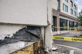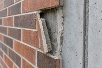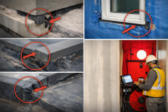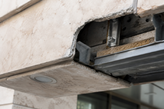
- The transition zone between below-grade waterproofing and above-grade WRB systems has no assigned trade owner on most commercial projects.
- Substrate moisture content, form release agents and temperature thresholds are rarely verified before peel-and-stick membranes are applied.
- IBC 2021 is explicitly silent on membrane termination height and transition detailing leaving a code-free zone at this condition.
- Manufacturer warranty language routinely excludes the transition zone meaning owners believe they have coverage they do not actually have.
- A pre-backfill hold point with photographic documentation is the only reliable mechanism for catching transition failures before they are buried.
Below-Grade-to-Above-Grade Membrane Transitions
The Transition Nobody Owns: Why Below-Grade-to-Above-Grade Handoffs Keep Failing
The physical zone in question spans roughly 12 to 24 inches of wall assembly: from the top termination of the below-grade waterproofing membrane to the beginning of the above-grade water-resistive barrier or air barrier system. It is a narrow band.
It is also where the four control layers (water, air, vapor and thermal) are most likely to be discontinuous, uncoordinated and unverified before permanent concealment by backfill or cladding.
The trade ownership gap is structural, not accidental. The waterproofing subcontractor’s scope ends at or near grade.
The cladding and WRB installer’s scope begins above grade. The general contractor rarely assigns explicit responsibility for the interface in subcontract documents and the transition condition does not appear on most RFI logs because nobody has been asked to own it.
The specification gap reinforces the field gap. Most project manuals treat Division 07 10 00 (dampproofing and waterproofing) and Division 07 25 00 (WRB and air barriers) as independent sections with no cross-referencing language at the transition.
Neither section typically requires a coordination drawing for the interface condition. A specifier writing both sections from the same master specification system can produce two technically compliant sections that are functionally incompatible at the one location where they must connect.
That outcome is common enough that it should be treated as the default condition, not the exception.
ASTM E2266 (Standard Guide for Design and Construction of Low-Rise Frame Building Wall Systems) and ASTM E2556 address WRB performance but neither standard governs the transition condition explicitly. The gap in the standards mirrors the gap in the field.
That is not a coincidence. Standards committees are organized around product categories and trade scopes and the transition zone falls between both.
Until a standard is written specifically to govern multi-membrane interface conditions at grade, the burden falls entirely on project-specific specification language and pre-installation coordination, neither of which happens reliably without an assigned owner.
Concrete, Contamination and Cold: Substrate Variables That Determine Whether Peel-and-Stick Actually Sticks
Concrete substrate moisture content is the primary adhesion variable at this transition and it is almost never measured. Most self-adhered membrane manufacturers require surface moisture content below 12 to 15 percent at time of application; verify this threshold against the specific product data sheet because it varies.
At the transition zone, the concrete has been in continuous contact with soil moisture and has typically never been tested before membrane application. The assumption that the surface looks dry is not a substitute for a quantitative reading.
A Tramex CMEXpert II or equivalent impedance-based meter takes less than two minutes to produce a reading at multiple points across the transition zone. That reading should be logged and included in the pre-installation documentation.
On projects where this step has been added to the pre-installation checklist, field teams consistently report finding moisture readings above manufacturer thresholds on walls that appeared visually dry, particularly on north-facing walls and in shaded below-grade conditions where evaporation is slow.
Surface preparation failures are equally common. Concrete laitance, form release agents and curing compounds are present on virtually every cast-in-place foundation wall.
They are almost never removed at the transition zone because the area appears visually clean and is not flagged in pre-installation checklists. No self-adhered membrane achieves rated adhesion over form release agent.
This is not a nuance; it is a basic material incompatibility that shows up in forensic investigations with remarkable consistency. The standard remediation is mechanical abrasion with a wire brush or grinder followed by vacuuming and priming, a process that takes minutes per linear foot but is routinely skipped because it was never written into the scope.
ICRI Technical Guideline 310.2R (Selecting and Specifying Concrete Surface Preparation for Sealers, Coatings, Polymer Overlays and Concrete Repair) provides a concrete surface profile classification system that can be referenced directly in the waterproofing specification to establish a minimum surface preparation standard at the transition zone. CSP 3 is the typical minimum for self-adhered membranes; requiring it by reference gives the inspector a defensible standard to enforce.
Temperature thresholds create a third failure pathway. Most self-adhered membranes require substrate and ambient temperatures above 40°F at application and during initial cure; some products require 50°F minimum.
IBC Section 1805 does not address application temperature, which means enforcement defaults entirely to product data sheets that field inspectors rarely review and subcontractors rarely produce at the time of application. On projects in cold climates, membrane application in marginal temperature conditions is common during fall and winter construction schedules when the schedule pressure to complete below-grade work before freeze-up is high.
The result is adhesion failure that does not manifest until the first heating season, when thermal movement at the transition zone opens the lap. Requiring the subcontractor to submit a temperature log for the 24-hour period surrounding membrane application, tied to a specific hold point in the inspection plan, is the only field mechanism that reliably catches this condition before it is buried.
Primer compatibility at the transition zone deserves specific attention. Butyl-based membranes and rubberized asphalt membranes require different primers and they are not interchangeable.
When the below-grade system and the above-grade system come from different manufacturers (the default condition on most commercial projects), primer compatibility across the lap zone is rarely verified by anyone. The result is adhesion failure at the one location where the lap must be watertight.
Some manufacturers publish explicit lists of compatible and incompatible primers; others require a written compatibility inquiry submitted to their technical department. Either path takes less time than a single forensic investigation and both should be required submittals before the pre-installation conference.
Detailing the Interface: What the Transition Zone Looks Like in Three Dimensions
Three physical configurations account for most commercial transition conditions and each requires a fundamentally different membrane termination and lap strategy. The first is a foundation wall flush with the above-grade wall framing plane; this is the simplest geometry and still fails routinely because the shingled lap dimension is never verified.
The second is a foundation wall set back with a ledge or shelf angle supporting the above-grade assembly; this configuration creates a horizontal surface that collects water and requires a separate flashing membrane across the ledge before the above-grade WRB begins. The third is a foundation wall projecting beyond the above-grade wall plane; this configuration requires the below-grade membrane to terminate on the projection face and the above-grade system to bridge back to the primary wall plane, a condition that almost no manufacturer detail addresses directly.
On the projecting foundation wall configuration, the designer must produce a project-specific detail because no standard manufacturer drawing covers the geometry. That detail needs to show the membrane termination height, the lap dimension, the flashing membrane across the projection top and the connection back to the above-grade system, all in a single coordinated drawing that both installers have reviewed and signed off on before work begins.
The termination bar and sealant requirement at the top edge of the below-grade membrane is the most consistently omitted detail in this zone. Most manufacturers require a metal termination bar mechanically fastened at maximum 6-inch spacing with a compatible sealant bead at the top edge.
This detail is routinely skipped at the transition because the installer assumes the above-grade system will cover and protect the membrane edge. That assumption fails when the above-grade system is applied by a different trade weeks later under different conditions.
When the termination bar is omitted, the membrane top edge is free to peel back under thermal cycling, wind pressure differential and construction traffic loading. The sealant bead at the top edge serves a separate function from the termination bar: it prevents water from migrating behind the membrane face at the one location where the membrane is not bonded to a continuous substrate on both faces.
Both elements are required; neither is optional.
Lap geometry is where the physics of water management either works or does not. The above-grade WRB or self-adhered membrane must lap over the top of the below-grade membrane in a shingled orientation, not a reverse lap.
Minimum lap dimensions typically run 2 to 4 inches per manufacturer requirements, but this dimension is never verified in the field because no one has been assigned to verify it. A reverse lap at this condition, where the below-grade membrane laps over the top of the above-grade system, creates a direct water entry path at the joint under any positive pressure condition.
NCMA TEK 19-5A (Flashing Strategies for Concrete Masonry Walls) documents the shingling logic for masonry assemblies; the same principle applies to all cladding systems regardless of substrate. The coordination drawing requirement described in the closing section of this article is the only reliable mechanism for verifying lap orientation before the condition is concealed.
What the Code Requires, What It Ignores and Where the Gap Lives
IBC 2021 Section 1805.3 addresses waterproofing and dampproofing for below-grade walls in specific terms regarding membrane type, application method and drainage requirements. It does not specify membrane termination height above grade.
It does not address transition detailing. The code is explicitly silent on the handoff between the below-grade system and the above-grade envelope assembly.
The termination height question matters practically because finished grade is not always where the drawings show it. On projects with sloped sites, retaining walls or landscape berms, the finished grade plane at the transition zone can vary by 12 inches or more around the building perimeter.
A membrane terminated at a fixed height above the structural slab elevation may be below finished grade on one elevation and 18 inches above it on another. Neither condition is addressed by Section 1805.3 and neither triggers a code correction notice from a plan reviewer.
IBC 2021 Section 1402.2 requires exterior walls to provide a weather-resistant exterior wall envelope but does not define how that envelope connects to the below-grade waterproofing system. The two code sections exist in separate chapters and are never cross-referenced.
A project can satisfy both sections independently while leaving the transition zone completely unaddressed. This structural gap in the code means that a plan reviewer examining the building permit submittal has no code basis for requiring a transition detail, even on a project where the below-grade and above-grade systems are clearly incompatible.
The design team can produce a code-compliant set of drawings with no transition detail shown and no reviewer can require one under current IBC language.
IECC 2021 Section C402.5 requires a continuous air barrier assembly for commercial construction. The air barrier continuity obligation effectively disappears below grade in most code interpretations; the section does not address continuity through the below-grade transition zone and most building officials do not require documentation of air barrier continuity at this condition.
The practical consequence is that a building can pass air barrier inspection with a documented gap at the transition zone because the inspector has no code section to cite when writing a correction. The air barrier continuity requirement in C402.5 is one of the more technically demanding provisions in the commercial energy code and the transition zone is the most common location where continuity is broken without consequence.
Some jurisdictions are beginning to close this gap indirectly. The Washington State Energy Code and the Massachusetts Stretch Code impose air barrier continuity documentation requirements that implicitly force transition detailing onto the design team.
Enforcement remains inconsistent even in those jurisdictions. The practical implication is that the transition condition is currently a code-free zone on most commercial projects in most states, which means the only enforceable requirements are manufacturer installation requirements and those are only enforceable if someone has contractually required compliance with them.
Reading the Fine Print: How Manufacturer Details Handle the Transition Condition
Most manufacturer-published transition details show a membrane wrapping a clean, idealized corner with no competing membrane, no shelf angle, no ledge and no cladding system. The detail is a best-case abstraction drawn to illustrate membrane behavior, not to coordinate a multi-trade interface.
Treating it as a construction document is the first mistake most project teams make. The second mistake is assuming that a detail published by the below-grade membrane manufacturer has been reviewed or approved by the above-grade WRB manufacturer.
It has not. Each manufacturer’s published detail shows their own product in the most favorable light possible.
Neither detail shows the other manufacturer’s product, the lap zone between the two systems or the substrate preparation requirements at the interface. The design team is responsible for producing a project-specific detail that integrates both systems and that detail needs to be reviewed by both manufacturers’ technical representatives before it is issued for construction.
The warranty gap is pre-built into most below-grade waterproofing warranties. Most explicitly exclude damage caused by improper termination or failure of adjacent systems.
This means the transition zone failure is excluded from warranty coverage before the project breaks ground. The warranty language is not deceptive; it reflects a rational limitation on what a single manufacturer can warrant when their product interfaces with another manufacturer’s system installed by a different trade under conditions the first manufacturer never specified.
The problem is that nobody tells the owner this until litigation begins. A standard below-grade waterproofing warranty on a commercial project may cover the field membrane for 10 to 20 years while excluding the transition zone entirely.
The owner believes they have a warranted envelope. The manufacturer believes they have a clearly limited warranty.
Both are correct and the gap between those two positions is where the litigation lives. Requiring the manufacturer to provide a written statement of what the warranty does and does not cover at the transition condition, as a required submittal before the pre-installation conference, forces that conversation to happen before installation rather than after failure.
Multi-manufacturer compatibility is the technical core of the problem. When the below-grade membrane is a rubberized asphalt self-adhered product and the above-grade system is a butyl-based or acrylic WRB, the two materials may not bond reliably at the lap zone.
Some combinations will delaminate under thermal cycling even when the initial bond appears adequate. The only way to verify compatibility is to require a written compatibility statement from both manufacturers before installation begins, a step that is almost never included in pre-construction submittals.
Some manufacturers have begun publishing compatibility matrices that list tested combinations with other manufacturers’ products; these matrices are a useful starting point but are not a substitute for a project-specific written statement because product formulations change and the matrix may not reflect the current version of either product.
The specification fix is straightforward: require the contractor to obtain a written joint compatibility statement from both membrane manufacturers prior to the pre-installation conference. Make that statement a required submittal.
This costs nothing and eliminates the most common warranty dispute at this condition.
Field Sequencing: The Timing Problem That Undermines Every Good Detail
Even when the transition is correctly detailed on paper, field sequencing destroys it. The below-grade membrane is typically applied before the above-grade framing is complete, before the WRB installer has mobilized and before anyone has verified the termination height relative to the finished grade plane.
The membrane top edge sits exposed to UV degradation, construction traffic and contamination for weeks or months before the above-grade system is applied. On a typical commercial project with a 6-to-8-month structure-to-enclosure schedule, the gap between below-grade membrane application and WRB installation can easily exceed 90 days.
During that window, the exposed membrane termination is subject to foot traffic from other trades, overspray from concrete work, physical damage from formwork stripping and UV degradation that no inspection process catches because nobody is assigned to monitor it.
Rubberized asphalt self-adhered membranes are particularly vulnerable to UV exposure at exposed terminations. Most manufacturers limit UV exposure to 30 to 60 days before requiring the membrane to be covered or the exposed section to be replaced.
This limit is almost never tracked on a commercial project. By the time the WRB installer arrives, the top 6 to 12 inches of the below-grade membrane may have degraded to the point where adhesion at the lap zone is compromised regardless of how well the lap is executed.
The degradation is not always visible. UV-damaged rubberized asphalt can appear intact while having lost the surface tack required for adhesion to the overlapping WRB.
A peel test at the lap zone, performed before the WRB is fully applied, is the only reliable way to verify that the bond is adequate. That test should be a required field verification step, not an optional quality control measure.
The sequencing fix requires a protected termination detail installed by the waterproofing subcontractor at the time of membrane application, not deferred to the WRB installer. This means the termination bar, sealant and a temporary protection course are installed before backfill and before the waterproofing subcontractor demobilizes.
The temporary protection course can be a self-adhered protection sheet, a rigid protection board extending above the termination bar or a peel-and-stick cap strip that the WRB installer removes and replaces with the final lap. The specific method depends on the membrane system and the expected exposure duration, but the principle is the same in all cases: the termination condition must be protected and verified before the waterproofing subcontractor leaves the site, because once they demobilize, accountability for the condition transfers to whoever is on site next and that trade has no contractual obligation to protect someone else’s work.
The WRB installer then laps over a protected, verified termination rather than a degraded exposed edge.
Closing the Gap Before Backfill: A Protocol That Actually Works
The transition condition fails by default when it is left to field improvisation. It succeeds when it is treated as a separate inspected condition with a specific owner, a specific detail and a specific hold point before backfill.
The practical protocol is this: assign the transition zone explicitly in the waterproofing subcontract, require a coordination drawing signed by both the waterproofing and WRB installers before the pre-installation conference, require a moisture content reading at the substrate within 24 hours of membrane application, require the termination bar and sealant to be installed by the waterproofing subcontractor before demobilization and establish a hold point in the inspection plan that prevents backfill until the transition condition has been photographically documented and reviewed by the envelope consultant. The photographic documentation requirement is not administrative overhead; it is the only record that exists once backfill covers the condition.
On projects where transition zone failures have been investigated forensically, the absence of pre-backfill documentation is a consistent finding. The photographs do not prevent failure, but they establish the condition at the time of concealment and allow the investigation to distinguish between installation defects and post-installation damage, a distinction that matters significantly in warranty and liability disputes.
This is not a new technology problem. Self-adhered membranes have been applied at below-grade transitions for decades.
The failure rate at this condition persists because the coordination infrastructure around the installation has never matched the technical requirements of the detail. The forensic record on this is consistent enough that any envelope consultant who does not require a transition zone hold point on a below-grade project with occupied space is accepting a known risk on behalf of their client.
The hold point costs one inspection visit. The remediation of a failed transition zone on an occupied building, which requires excavation, membrane removal, substrate re-preparation and re-application under conditions that are almost always worse than the original installation, costs orders of magnitude more.
The protocol described here does not require new products, new standards or new trades. It requires assigning ownership, requiring documentation and treating a 12-inch band of wall assembly with the same inspection discipline applied to every other condition that gets permanently buried.