
Silicone Foam Firestopping at Exterior Curtainwall Perimeter Joints: Where the Compression Fit Assumption Fails and Why the Safing Insulation Thickness Gap Is the Code Compliance Risk Nobody Inspects
A special inspector reviewing a 34-story commercial tower during punch-list walks discovers that safing insulation at the curtainwall perimeter has been installed at 20% compression across 60% of the floor stack. That is half the minimum compression ratio required by the tested assembly.
The silicone foam has been applied over the undersized safing in a single pass, creating a visually complete installation that will fail under the fire exposure conditions the tested assembly was specifically designed to resist. No flag was raised during construction because perimeter firestopping fell outside the standard special inspection scope on the project’s inspection and testing plan.
The building passed its Certificate of Occupancy review. It is occupied right now.
This is not an isolated case. It is the standard outcome when perimeter firestopping is treated as a close-out line item rather than a sequenced, inspected assembly.
What the IBC Actually Requires at the Curtainwall-to-Slab Interface
The 2021 IBC Section 715.4 establishes perimeter fire containment requirements at exterior curtainwall-to-floor slab interfaces as a distinct code obligation, separate from through-penetration firestopping under Section 714. This distinction matters operationally.
Through-penetration firestopping addresses discrete openings in fire-rated assemblies; perimeter fire barriers address the continuous linear joint between the exterior envelope system and the floor slab edge. The two systems serve different geometric conditions and are tested by different standards.
The code mandates that perimeter fire barrier assemblies be tested in accordance with ASTM E2307, the Standard Test Method for Determining Fire Resistance of Perimeter Fire Barriers Using Intermediate-Scale, Multi-story Test Apparatus. ASTM E2307 was significantly revised in 2017 to incorporate dynamic movement requirements, recognizing that curtainwall systems deflect under thermal load and seismic drift.
The 2017 revision added cyclic movement protocols that simulate inter-story drift during a seismic event concurrent with fire exposure, a condition that static test methods cannot replicate. ASTM E119, which governs fire-rated wall and floor assemblies, does not apply here.
Specifying or accepting ASTM E119 test data as the basis for perimeter fire barrier compliance is a fundamental error that appears in submittals with enough regularity that it warrants explicit rejection language in the project specification.
The conflation of “perimeter fire barrier” with “firestop system” is one of the most persistent specification errors I encounter on high-rise projects. Submittals referencing UL 1479-listed through-penetration products at the curtainwall perimeter are not responsive to Section 715.4 requirements.
UL 1479 governs through-penetration firestop systems tested under ASTM E814; it addresses a fundamentally different geometry and failure mode than the continuous linear joint condition at the curtainwall perimeter. A submittal that lists a UL 1479 product at this location has answered the wrong question entirely and an approving reviewer who does not catch that substitution has introduced a compliance gap that will not be visible in any subsequent inspection.
The intent of Section 715.4 is floor-to-floor compartmentalization: the perimeter joint assembly must prevent flame and hot gas migration between occupied floors for the rated duration, typically one or two hours depending on the building’s construction type and occupancy classification. In a Type I-A high-rise with a two-hour floor assembly rating, the perimeter fire barrier must match that rating.
The assembly is not a supplementary detail. It is the fire-rated boundary condition at the most geometrically complex location in the entire floor plate and it runs continuously around the building perimeter for every occupied floor.
How Tested Assemblies Define Safing Insulation Parameters and Why Those Numbers Are Not Suggestions
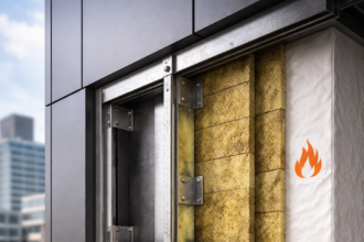
UL-listed and FM-approved perimeter fire barrier assemblies specify safing insulation density, thickness and compression ratio as fixed tested parameters. They are not ranges.
They are not field-adjustable values. The UL Fire Resistance Directory CW-D series assemblies are explicit: a system like UL CW-D-2047 specifies 4 pcf minimum density mineral wool safing at 25% minimum compression with defined thickness tolerances.
Deviations outside those tolerances are not covered by the listing. The listing does not say “approximately 25% compression.
” It says 25% minimum.
Density is not interchangeable between products that appear visually similar. A 3 pcf mineral wool batt and a 4 pcf mineral wool batt look identical in the field.
They are not the same product for listing purposes. The 3 pcf material has lower compressive stiffness, which means it reaches the same installed thickness at a lower contact pressure.
That lower contact pressure is the mechanism failure. Installers and even some inspectors routinely accept any mineral wool safing product as equivalent because the material category is the same.
The listing does not recognize material category equivalence. It recognizes the specific tested density and substituting a lower-density product at the same nominal thickness produces a non-conforming installation regardless of how the foam is applied over it.
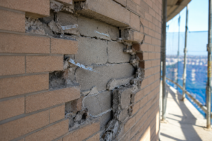
Compression ratio is the mechanical mechanism that creates the friction-fit seal against the curtainwall system’s back pan or spandrel. The compressed safing exerts lateral contact pressure against both the slab edge and the back pan face simultaneously.
Reduce the compression and you reduce that contact pressure directly. At 20% compression, the safing is no longer performing the sealing function the assembly was tested to demonstrate.
Hot gas bypass at the safing-to-back-pan interface is the failure mode and it occurs before the silicone foam is even thermally challenged. The foam, in that scenario, is not the primary seal.
It is a secondary component applied over a primary component that has already failed to meet its tested condition.
Safing insulation thickness must match the floor slab edge depth, the safing slot dimension. When the curtainwall system is set with a larger-than-designed gap, installers routinely substitute thinner material rather than ordering correct thickness.
This substitution invalidates the tested assembly regardless of how the silicone foam is subsequently applied. UL 2079, the product-level qualification standard underlying listed assembly performance, establishes the test protocol; the listed assembly then constrains the field installation to the exact geometry tested.
FM 4991 governs FM-approved systems under the same logic. Both standards treat the tested geometry as the compliance boundary.
There is no provision in either standard for engineering judgment substitutions in the field.
The specification-to-field gap here is structural. The spec references the UL assembly number.
The submittal gets approved. Then the safing arrives on site in whatever thickness the curtainwall sub had in stock, because the purchase order was written against a generic mineral wool line item rather than the specific product and thickness required by the listing.
By the time the firestopping subcontractor arrives, the wrong material is already installed and the curtainwall enclosure is complete. Correcting it requires removing and reinstalling safing in an enclosed condition, which no subcontractor will do voluntarily without a formal nonconformance finding and a written direction to correct.
The Silicone Foam Coverage Assumption and Where Field Application Diverges from Tested Geometry
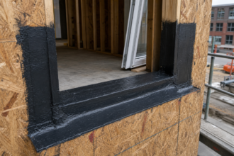
Tested assemblies specify silicone foam bead geometry: width, depth and position relative to the interior face of the safing insulation and the floor slab edge. These are geometric constraints, not aesthetic guidelines.
The foam must contact both the slab edge and the interior face of the curtainwall back pan simultaneously across the full joint width. That simultaneous contact is what creates the tested seal geometry.
Miss either substrate and you have a bypass path.
Field installers commonly apply silicone foam in a single continuous pass without verifying that the foam contacts both substrates across the full joint width. The result is unbonded edges.
Those unbonded edges are not visible from below after installation. They look correct.
They are not. The foam surface presents as a continuous bead, but the bond line at the back pan face or the slab edge is incomplete.
Under fire exposure, the unbonded edge lifts and the bypass path opens. The failure mode is not foam combustion or foam degradation.
It is geometric loss of the seal boundary at the substrate interface.
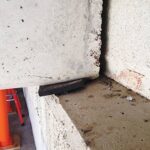
The more consequential failure mode is what I call capping behavior. When safing is under-compressed, the silicone foam bridges the gap without fully contacting the safing face, creating a hollow void behind the foam cap.
The safing surface is recessed below the plane where the foam bead was applied and the foam spans across that recess rather than bearing against it. Under fire exposure temperatures, that void collapses as the safing compresses further under thermal load.
The foam cap loses its substrate support and the assembly fails in a mode the tested geometry was specifically designed to prevent. This failure sequence is not hypothetical.
It is the documented failure mode in post-test analysis of non-conforming installations subjected to ASTM E2307 exposure conditions.
Foam expansion ratio and cure time are also temperature and humidity dependent. Manufacturer installation instructions for silicone RTV foam products specify minimum substrate temperatures, typically 40°F and foam bead dimensions tied to the specific UL assembly listing.
Cold-weather installations without temperature conditioning of the substrate produce under-expanded foam that does not achieve the tested cross-sectional geometry. A bead that looks correct at installation may be dimensionally deficient.
The listing is voided by the field condition, not by any visible defect. In northern climate projects where curtainwall enclosure occurs in late fall or winter, this condition is not an edge case.
It is the standard installation environment for a significant portion of the building perimeter and it requires active management through substrate temperature documentation and foam bead dimensional verification before the joint is accepted as complete.
Some silicone foam products also have defined shelf-life and mixing ratio requirements for two-component formulations. A product applied from an expired cartridge or with an improperly conditioned component ratio will not achieve the tested expansion ratio regardless of substrate temperature.
These are installation quality controls that belong in the specification and the inspection program, not in the manufacturer’s technical data sheet alone.
Why Schedule Compression Systematically Produces Non-Conforming Installations
Perimeter firestopping occupies a chronically compressed position in the construction sequence. It installs in the gap between curtainwall enclosure and interior fit-out and it is treated as a close-out item rather than a sequenced inspection hold point.
Every schedule pressure on the project lands on this assembly. When the interior fit-out subcontractors are waiting for floor access and the general contractor is managing float on the critical path, the perimeter firestopping scope gets compressed from both ends of the schedule simultaneously.
The two-trade split makes it worse. Safing insulation is frequently installed by the curtainwall subcontractor as part of system enclosure.
Silicone foam is applied by a separate firestopping subcontractor weeks later. No single party owns the complete assembly verification.
The curtainwall sub considers their scope complete when the safing is in. The firestopping sub arrives to an existing condition they did not install and cannot easily measure.
If the safing is already covered by interior framing or MEP rough-in at the perimeter, the firestopping subcontractor cannot verify compression without destructive access. They install to what they can see and document what they can reach.
When interior slab edge conditions change after the curtainwall is set, including MEP penetrations added through the slab edge, slab edge form variations from pour inconsistencies or post-installed embed conflicts, the safing slot dimension changes locally. The firestopping subcontractor is not notified of those changes because they are not in the RFI distribution for curtainwall or structural issues.
They install to original dimensions against a field condition that no longer matches the design. The result is localized non-conformance at exactly the locations where the assembly geometry is most complex and most likely to have been compromised.
Photographic documentation of “complete” installation is accepted as verification without any dimensional confirmation of compression ratio or foam geometry. Project managers close the line item.
The photos satisfy the RFI log. They do not satisfy the tested assembly requirements.
A photograph of a continuous silicone foam bead at the perimeter joint confirms that foam was applied. It confirms nothing about compression ratio, foam bead depth, substrate contact or substrate temperature at the time of application.
AGC and AISC sequencing guidance addresses trade coordination broadly, but perimeter firestopping specifically lacks a defined inspection hold point in most project delivery frameworks. The absence of that hold point means the assembly is accepted on visual appearance alone, which is the least informative verification method available for a system whose critical performance parameters are entirely dimensional.
The schedule dynamic also affects material procurement. Safing insulation ordered to match the listed assembly’s specified thickness and density has a lead time.
When the curtainwall enclosure schedule accelerates, the curtainwall sub procures whatever safing is available from their standard supplier. That material may be the correct density but the wrong thickness or the correct thickness but a lower density product from a different manufacturer.
Both substitutions invalidate the listing. Neither substitution is visible in the installed condition without measurement and material verification against the approved submittal.
The Special Inspection Gap: Who Is Responsible for Verifying This Assembly and Who Actually Does It
IBC Section 1705.16 requires special inspection of exterior wall envelope systems on certain occupancy and construction type combinations. That section provides the closest existing authority for anchoring perimeter firestopping inspection to the special inspection program.
In practice, the statement of special inspections on most high-rise commercial projects does not include perimeter firestopping as a discrete inspection scope item. The section is cited in the statement of special inspections as the authority for curtainwall anchor inspection and structural silicone verification, but the perimeter fire barrier assembly is not listed as a separate line item with its own verification criteria and inspection frequency.
The result is a verified gap. The curtainwall special inspector confirms mullion anchor torque values and structural silicone bite dimensions.
The firestopping inspector, when one exists at all, typically verifies through-penetration firestop systems under Section 714. The perimeter fire barrier assembly under Section 715. 4 falls between those two scopes on most inspection and testing plans.
Neither inspector has been assigned the scope, neither inspector has the listed assembly documentation in their field kit and neither inspector has a defined rejection threshold for compression ratio or foam geometry. The assembly is installed, photographed and closed without a qualified party ever confirming that the dimensional requirements of the tested assembly were met.
This is not a contractor failure in isolation. It is a program design failure.
The special inspection program is a contract document. It is prepared by the engineer of record or the special inspection firm under the engineer’s direction.
It defines scope, frequency and acceptance criteria for every inspected system on the project. When perimeter firestopping is absent from that document, the absence reflects a decision made at the contract document stage, not a field oversight.
The contractor cannot be held to an inspection standard that was never established in the program. The building official cannot enforce an inspection that was never scoped.
The failure propagates forward from the program design stage to the Certificate of Occupancy without any point at which a qualified party was contractually required to verify the assembly.
The IBC requires the assembly under Section 715.4. The IBC provides inspection authority under Chapter 17. The project team simply does not connect those two requirements into a defined inspection scope with hold points, dimensional verification criteria and rejection thresholds.
Connecting them requires the engineer of record to read both sections together during the preparation of the statement of special inspections and to write perimeter fire barrier assembly verification into the program as a discrete scope item with the same specificity applied to structural connections or fire-rated wall assemblies.
The fix is straightforward in principle: the statement of special inspections must explicitly list perimeter fire barrier assemblies as an inspected scope, define the verification criteria including compression ratio measurement, foam bead geometry confirmation and substrate temperature documentation for cold-weather installs and assign inspection authority to a qualified party with access to the UL or FM assembly listing being installed. That qualified party must be present at the time of safing installation, not weeks later when the foam is being applied over a condition they cannot measure.
Straightforward in principle. Rare in practice.
Reading the UL Listing Before You Accept the Submittal
The submittal review stage is the last opportunity to catch assembly mismatches before they become field conditions. Most submittal reviewers confirm that a UL assembly number appears on the submittal and that the listed products are included.
That is not sufficient. A submittal that lists the correct UL assembly number but specifies safing insulation from a manufacturer whose product is not listed in that assembly is non-conforming on its face.
The UL CW-D series listings identify specific safing products by manufacturer and product designation. Substituting a different manufacturer’s mineral wool product, even one with the same nominal density, requires either a separate listed assembly that includes that product or a UL engineering judgment letter specific to the substitution.
Neither is common in submittals. Both are required for compliance.
Pull the actual UL assembly listing from the UL Fire Resistance Directory and read the installation requirements in full. Confirm that the specified safing insulation density matches the listing, noting that 4 pcf is common and that 3 pcf mineral wool products do not satisfy listings requiring 4 pcf.
Confirm that the safing thickness specified in the listing matches the actual safing slot dimension on the project’s curtainwall shop drawings. This comparison requires having both documents open simultaneously during the review.
The curtainwall shop drawings define the slot geometry. The UL listing defines the required safing thickness for that geometry.
If those two dimensions do not align, the submittal is not responsive and the discrepancy must be resolved before approval.
Confirm that the compression ratio requirement is achievable given the nominal thickness of the safing and the actual slot dimension. If the curtainwall shop drawings show a 4-inch safing slot and the listing requires 4-inch nominal safing