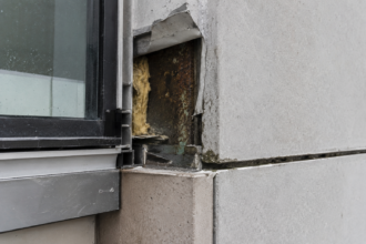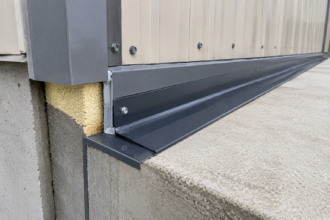
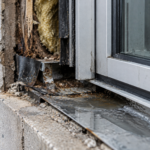
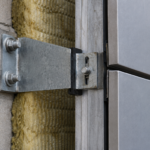
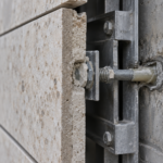
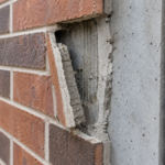
- Increasing sub-girt standoff depth to meet insulation requirements changes the structural behavior of concealed clip connections in ways most teams never analyze.
- Concealed clip systems create fewer but larger thermal bridges while exposed fasteners create more frequent point bridges requiring different calculation methods.
- Manufacturer load tables for concealed clips are typically calibrated for shallow cavities and are not valid at greater standoff depths without independent engineering review.
- Thermal ratcheting in concealed clip systems accumulates invisibly over time and can compromise clip engagement before any exterior distress becomes visible.
- Specification language must explicitly require re-analysis whenever sub-girt standoff depth changes after the attachment system has been specified.
A metal rainscreen installation on a Pacific Northwest mixed-use project experienced progressive panel displacement eighteen months after substantial completion. The cause was not wind load exceedance.
It was cumulative thermal ratcheting at concealed clip locations where the sub-girt standoff depth had been increased mid-design to meet ASHRAE 90.1-2019 continuous insulation requirements. The clips, specified from a manufacturer load table calibrated for a 1.5-inch cavity, were now operating at a 3-inch standoff with no reanalysis of the resulting moment arm.
The failure was aesthetic before it became structural. The structural risk had been present from day one.
That sequence, aesthetic concern driving specification, thermal requirement forcing a geometry change, engineer never re-engaged, is not an edge case. It is the default workflow on most commercial facade projects.
Why the Fastener Decision Gets Made Too Early and at the Wrong Level
Concealed versus exposed fastener selection is routinely driven by the architect’s finish preference or owner aesthetic brief, locked in at schematic design before the envelope engineer is engaged. By the time sub-girt geometry is being detailed, the panel system is already specified and the engineer’s ability to flag attachment incompatibilities is severely constrained.
The decision sequence should run: thermal cavity depth, then sub-girt type and standoff, then attachment method, then panel selection. In practice it runs in reverse.
This inversion is not accidental. It follows procurement logic.
Owners see renderings, approve materials and move on. The envelope consultant, if retained at all, enters the project during design development and inherits decisions that have already been made.
NIBS Guideline 3, Building Enclosure Commissioning, identifies envelope system selection sequencing as one of the most common sources of coordination failures in facade assemblies. The guideline recommends that attachment system geometry be established before panel selection is finalized.
That recommendation is routinely ignored on design-build and CM-at-risk delivery methods, where manufacturer representative influence frequently bypasses the envelope consultant entirely. The result is a specification that looks complete on paper and is structurally compromised in the field.
The manufacturer representative problem deserves more direct attention than it typically receives in post-project reviews. Representatives are trained to close specifications, not to flag incompatibilities between their product and the thermal assembly it is being asked to serve.
A representative who identifies a standoff depth conflict and recommends a different product is working against their own sales objective. That incentive structure does not change.
The envelope consultant’s role is to function as the counterweight to it and that role requires early engagement, not late-stage submittal review. When the consultant is brought in after the panel system is specified and the cavity depth is still in flux, the project is already in a condition where the most consequential decisions have been made by people without the authority or technical background to make them correctly.
Thermal Bridging Is Not Equal Between the Two Systems and the Gap Is Widening
Exposed fastener systems create discrete, repetitive point bridges through the insulation plane at every fastener penetration. Concealed clip systems create fewer but geometrically larger conductive elements: the clip body and sub-girt flange contact area.
Neither system is thermally neutral. The question is which bridging geometry dominates under the specific assembly configuration.
Linear thermal transmittance, expressed as a Psi-value, for a typical concealed aluminum clip through 3-inch mineral wool is measurably higher per connection than a single exposed screw. But exposed fasteners occur at four to six times greater frequency across a typical panel field.
The net effective R-value penalty depends on fastener spacing, clip material, insulation type and standoff depth. You cannot resolve this with a spreadsheet using nominal R-values.
You need the parallel path method at minimum and for complex clip profiles, ASTM C1363 hot box testing is the only method that captures actual three-dimensional bridging geometry.
ASHRAE 90.1-2022 Section 5. 8.
3 requires that sub-girt framing members penetrating the insulation layer be accounted for in the effective R-value calculation for the continuous insulation compliance path. Most project teams are still applying this requirement only to Z-girts and hat channels.
They are not applying it to clip standoff assemblies, which penetrate the insulation plane at discrete but thermally significant points.
Oak Ridge National Laboratory research has documented effective R-value reductions of 40 to 60 percent in aluminum-framed rainscreen assemblies when sub-girt bridging is fully accounted for. That range is not a rounding error.
It is the difference between meeting and failing the continuous insulation threshold in IECC Climate Zones 4 through 7. The isothermal plane method and the parallel path method produce significantly different results for the same assembly. Choosing one over the other is not a neutral technical decision.
The material selection for clips and sub-girts amplifies this problem significantly. Standard 6063-T5 aluminum has a thermal conductivity of approximately 116 BTU per hour per foot per degree Fahrenheit.
Stainless steel runs closer to 9. Thermally broken clip systems using polyamide thermal breaks or glass-fiber-reinforced nylon standoff elements can reduce the conductive path by 60 to 80 percent compared to an all-aluminum assembly at the same standoff depth. Those systems carry a cost premium and require their own structural evaluation, but in Climate Zones 6 through 8 the thermal performance difference is large enough that the premium is frequently justified on energy compliance grounds alone, before any condensation risk analysis is applied.
The condensation risk calculation at the clip location is a separate analysis from the effective R-value calculation and requires dew point mapping through the assembly cross-section at the clip, not just at the clear field. Both calculations are required.
Most project teams perform neither.
The Lever Arm Problem: How Deeper Cavities Change Structural Behavior at the Connection
A concealed clip cantilevering from a structural backup wall or stud framing behaves as a moment-resisting connection. As standoff depth increases to accommodate thicker insulation, the moment arm for out-of-plane wind load increases proportionally.
This is basic mechanics. What is not basic is how consistently project teams fail to apply it.
Most manufacturer load tables for concealed clip systems are developed and tested at 1.5- to 2-inch standoff depths. Published allowable loads are not linearly scalable to 3- or 4-inch standoffs without independent engineering analysis.
Two major aluminum clip system suppliers include footnotes in their load tables explicitly stating “valid for standoff depths not exceeding 2 inches. ” Those footnotes are routinely overlooked during specification and they are almost never surfaced during submittal review.
Exposed fastener systems are less sensitive to standoff depth for out-of-plane load transfer because the fastener bears directly on the panel and sub-girt in shear rather than in moment. That is a genuine structural advantage in deep-cavity assemblies.
It does not eliminate eccentricity at the panel-to-girt interface, but it keeps the primary load path in a more predictable geometry.
The sub-girt itself requires independent re-evaluation when cavity depth increases. A hat channel or Z-girt that performs adequately at a 1.5-inch standoff may be susceptible to local buckling or weak-axis bending failure at 3 inches under the same wind pressure.
AISI S100-16, the North American Specification for the Design of Cold-Formed Steel Structural Members, governs cold-formed sub-girt sections under combined axial and bending loads. Applying it is not optional when geometry changes.
It is the minimum standard of care and it requires re-analysis every time cavity depth changes from what was originally assumed in the load table.
The Pacific Northwest project described in the introduction failed precisely because this re-analysis was never triggered. The cavity depth change was processed as a coordination item between the insulation subcontractor and the facade installer.
It was never routed to the envelope engineer. No one on the project team identified the geometry change as a structural event requiring engineering review.
That is a process failure, but it is also a contract failure. The envelope engineer’s scope of services did not explicitly include review of geometry changes after design development.
That scope gap is common. It should be closed by contract language that requires the envelope engineer to review any change to sub-girt standoff depth, clip type or insulation thickness after the attachment system has been specified, regardless of which party initiates the change.
Differential Movement Accommodation: Where the Two Systems Behave Fundamentally Differently
Metal rainscreen panels expand and contract at rates governed by material and finish. Dark anodized or painted aluminum panels in direct sun can experience surface temperatures exceeding 160 degrees Fahrenheit in IECC Climate Zone 3, driving delta-T values that produce measurable dimensional change across a panel field.
The attachment system must accommodate this movement without transferring load to the panel face or the structural backup.
Concealed clip systems typically provide movement accommodation through slotted holes in the clip or a floating clip-to-rail interface. The tolerance stack between panel, clip, rail and sub-girt determines whether thermal movement is actually free or is being resisted and accumulating stress.
When that stack is tight, panels do not move freely. They ratchet.
Each thermal cycle advances the panel incrementally in the direction of least resistance until the connection is loaded beyond its design intent.
Exposed fastener systems accommodate movement through oversized holes in the panel with neoprene or EPDM washers. The washer durometer, compression set over time and UV degradation directly affect long-term movement capacity.
This is a maintenance variable that is almost never tracked after substantial completion. A washer that provides adequate movement accommodation at year one may be fully compressed and effectively rigid at year seven.
AAMA 501.5, the Test Method for Thermal Cycling of Exterior Walls, establishes a protocol for evaluating movement accommodation under realistic thermal cycling. It is rarely specified for rainscreen assemblies.
It should be a standard submittal requirement on any project where the panel material, finish color or climate zone creates significant thermal movement demand.
The ratcheting failure mode in concealed clip systems is particularly difficult to detect during construction because it does not produce visible distress until cumulative displacement has already compromised the connection geometry. A panel that has ratcheted 3/16 of an inch out of plane looks installed.
The clip engagement that was designed for a 3/8-inch bearing depth may now have 3/16 inch of bearing remaining. That condition is not visible from the exterior and is not detectable without removing the panel.
Specifying AAMA 501.5 testing on a mock-up before installation begins is the only reliable way to confirm that the tolerance stack in the actual assembly, not the theoretical assembly shown in the shop drawings, provides genuine movement accommodation under the thermal cycling the project will experience. The distinction between theoretical and actual tolerance stack is significant.
Shop drawings show nominal dimensions. Field installation introduces real-world variation at every interface and that variation consistently tightens the stack rather than loosening it.
The Sub-Girt Anchor: Where Both Systems Share a Common Failure Point
Regardless of whether the face attachment is concealed or exposed, both systems transfer load to the structural backup through the sub-girt anchor. This is the connection that receives the least attention and carries the most consequence.
At concrete and masonry substrates, sub-girt anchors are typically post-installed mechanical or adhesive anchors. Their capacity is well-established under direct shear and tension.
It is less well-established under combined loading that includes the moment contribution from a cantilevered sub-girt at depth. When cavity depth increases to meet continuous insulation requirements, that moment contribution increases.
The anchor design must be revisited. It frequently is not.
At light-gauge steel stud framing, sub-girt attachment is typically through-screw to the stud flange. The capacity of this connection under combined out-of-plane wind load and the eccentric moment from a deep sub-girt standoff is governed by the stud’s weak-axis bending resistance and the screw’s pull-through capacity in the stud flange.
Neither value is generous. Both values decrease as the sub-girt standoff increases.
The four control layers, water, air, vapor and thermal, all pass through or terminate at the sub-girt anchor location. Any penetration that compromises the air barrier at this point creates a defect that no amount of panel detailing will correct.
The anchor backup plate or bearing plate detail must be coordinated with the air barrier system before construction documents are issued.
Post-installed anchor design at concrete substrates is governed by ACI 318-19 Chapter 17, which addresses anchors under combined shear and tension through an interaction equation. The moment contribution from a cantilevered sub-girt at 3-inch standoff converts directly into a tension component at the anchor that does not appear in a simple shear-only calculation.
Structural engineers who are not facade specialists frequently miss this because they are accustomed to evaluating sub-girt anchors as shear connections. The facade load path does not work that way at depth.
The anchor must be evaluated under the actual combined loading, including the moment arm from the sub-girt standoff and the calculation must be updated whenever standoff depth changes. ICC-ES reports for post-installed anchors provide combined loading interaction data, but that data is only useful if the moment contribution is being calculated in the first place.
On projects where the structural engineer of record is reviewing facade anchor calculations without specific facade experience, the moment contribution from sub-girt standoff depth is the single most commonly missed load component.
What the Specification Should Actually Require
The concealed versus exposed fastener decision should be deferred until thermal cavity depth is established, not before. Once cavity depth is confirmed, the specification should require that the attachment system supplier provide load tables specific to the actual standoff depth being used, not generic tables with depth limitations buried in footnotes.
For concealed clip systems at standoffs exceeding 2 inches, require independent engineering analysis of the clip moment arm under the project-specific design wind pressure. Reference AISI S100-16 explicitly in the specification for cold-formed sub-girt sections.
Require ASTM C1363 hot box testing data for the actual clip profile if the project is in IECC Climate Zones 5 through 8 and the continuous insulation compliance path is being used.
For exposed fastener systems, specify washer material, durometer and UV resistance class. Require the contractor to document as-installed torque values.
Include a maintenance provision that addresses washer inspection at five-year intervals. This will be ignored by most owners.
Specify it anyway, because it establishes the design intent and creates a record if litigation follows.
The specification should also include a change control provision that is explicit about what triggers re-analysis. Any change to sub-girt standoff depth, clip model, insulation thickness or panel weight after the attachment system has been specified must be routed to the envelope engineer for written confirmation that the existing structural analysis remains valid.
That provision needs to appear in Division 07 under the rainscreen section and in the general conditions under submittal requirements. Placing it in only one location is not sufficient, because the change that triggers the re-analysis requirement will often be initiated by a subcontractor who never reads the technical specification section.
The general conditions language creates a contractual obligation that the contractor cannot disclaim by citing unfamiliarity with Division 07.
The project that opened this article was not a failure of materials. It was a failure of sequencing.
The clips were adequate for the original cavity depth. The insulation requirement was legitimate.
The error was treating those two facts as independent when they were not. Every time a thermal requirement forces a geometry change in a facade assembly, the structural analysis has to follow.
That connection is not optional and it is not automatic. Someone has to make it explicitly, in writing, before the drawings go to bid.