
- Barrier EIFS failures from the 1990s created insurance exclusions that still penalize modern drainage systems with a far better performance record.
- Drainage EIFS assemblies per ASTM E2568 deliver continuous R-15 insulation at lower installed cost than cavity walls in most regional markets.
- Window head flashing omission and substrate incompatibility remain the top two failure modes in commercial EIFS installed after 2010.
- WRB selection requires compatibility verification with EPS adhesive chemistry before specification to prevent delamination after installation.
- Third-party inspection holds at four defined checkpoints close the gap between specification requirements and what field crews actually install.
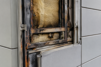
A building envelope consultant walks into a five-story medical office building clad in barrier EIFS installed in the mid-1990s. No drainage plane.
No transition flashings at window heads. Sealant failed years ago, probably within the first decade.
The interior damage is extensive across three floors, the litigation is expensive and the owner’s first instinct is to ban EIFS from every future project. That instinct is understandable.
The technical conclusion it produces is wrong.
Why EIFS Has a Reputation Problem It Has Partially Outgrown
The residential EIFS failures of the 1980s and 1990s were catastrophic and well-documented. Barrier systems with no drainage path trapped bulk water against OSB sheathing, producing rot, mold and structural degradation that generated thousands of claims.
North Carolina alone saw litigation involving tens of thousands of homes and the resulting class action settlements reshaped how the industry understood water management obligations in cladding systems. Commercial projects suffered less physical damage but enormous collateral damage in litigation exposure and insurance underwriting.
Carriers began writing blanket EIFS exclusions that persist in many policies today, long after the systems that caused those losses left the market.
The critical distinction is between barrier EIFS and drainage EIFS. Drainage systems integrate a continuous drainage plane between the EPS insulation board and the water-resistive barrier, terminating at a weep screed that allows bulk water to exit the assembly.
ASTM E2568 embeds drainage requirements directly into current specification language for polymer-based exterior insulation and finish systems. The market shifted substantially toward drainage systems after 2000. The reputation did not follow.
Insurance exclusion language and surety hesitancy still reference legacy system failures, creating a specification chilling effect that is disproportionate to the actual risk profile of a properly detailed drainage EIFS assembly. EIMA market data shows commercial specification rates recovering slowly relative to the system improvement timeline.
That gap costs owners real money in foregone thermal performance and cost-effective cladding options. A drainage EIFS assembly delivering continuous R-15 insulation across a steel-framed commercial wall outperforms a cavity wall with batt insulation on thermal bridging metrics alone and it does so at a lower installed cost per square foot in most regional markets.
Specifiers who default away from EIFS based on 1990s litigation history are denying their clients a legitimate performance option. The specification decision should rest on current system performance data, not on underwriting language written for a product that no longer exists.
How Drainage EIFS Actually Works and Where the Physics Demand Precision
The assembly reads from inside out: structural substrate, moisture-resistant sheathing, air and water-resistive barrier, drainage mat or back-cut EPS board, adhesively or mechanically attached EPS insulation, base coat with reinforcing mesh and finish coat. Each layer carries a distinct moisture management obligation.
The WRB is the primary water control layer. The drainage plane creates the capillary break and provides a bulk water path to the weep screed.
The base coat and finish coat are not waterproofing; they are weather-resistive cladding that will transmit incidental moisture under sustained exposure.
Vapor drive behavior varies significantly by climate zone. In Climate Zone 4 mixed-humid conditions, vapor drive reverses seasonally, which means the assembly must dry toward both interior and exterior depending on time of year.
A vapor retarder placed at the wrong location in this climate can trap moisture during the drying season. In Climate Zone 6, outward vapor drive dominates in winter and the EPS continuous insulation keeps the WRB above the dew point, which is exactly where you want it.
Effective R-value matters here; nominal R-value of the EPS board does not account for the thermal bridging at fasteners and attachment points.
Hygrothermal modeling using tools such as WUFI Pro can quantify the moisture accumulation risk at the sheathing layer across a full annual cycle for a given climate and assembly configuration. That analysis is not academic exercise on a commercial project with meaningful envelope area.
It is the basis for making defensible decisions about vapor retarder placement, EPS thickness and WRB vapor permeance requirements. A fluid-applied WRB with a vapor permeance of 10 perms behaves differently in a Zone 4 assembly than a self-adhered membrane at 0.1 perms and that difference shows up in the drying potential calculation before it shows up in the wall.
Precision is non-negotiable at two locations: WRB continuity at every penetration and weep screed clearance above grade and at horizontal terminations. Both are field execution problems as much as design problems.
The physics are unforgiving when either fails. Per IBC Section 1403.2 of the 2021 edition, exterior walls must provide weather protection and that obligation does not end at the design drawing.
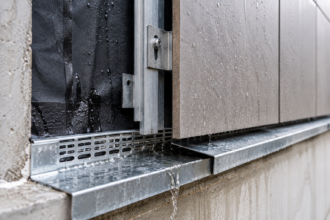
The minimum clearance of two inches between the bottom of the EIFS assembly and finished grade or adjacent horizontal surfaces is not a suggestion; it is the threshold below which bulk water wicking into the EPS base becomes a predictable outcome rather than a contingency.
The Four Failure Modes That Still Appear in Modern EIFS Installations
Failure Mode 1 is transition flashing omission or improper sequencing at fenestration heads. Water that bypasses the finish coat at a window head needs a positive drainage path back to the exterior.
Without through-wall flashing with end dams at this location, water tracks horizontally behind the WRB and enters the wall assembly through the path of least resistance. This failure appears in new construction.
It is not a legacy problem. Forensic investigations on commercial buildings completed after 2010 consistently identify window head flashing deficiencies as the primary water entry point, not finish coat degradation or sealant failure at field joints.
The detail is well-understood. The execution gap persists because window head flashing integration requires coordination between the fenestration installer and the EIFS applicator and that coordination is frequently absent when the two scopes belong to separate subcontractors with no contractual relationship to each other.
Failure Mode 2 is substrate incompatibility. EIFS applied over standard gypsum board meeting ASTM C36 will fail.
Standard gypsum board has no meaningful moisture resistance. When bulk water reaches the substrate, whether through a failed sealant joint or a compromised WRB lap, the board degrades before the drainage plane can function.
The substrate specification must require moisture-resistant gypsum sheathing per ASTM C1177 or glass-mat sheathing per ASTM C1278. This is a specification error before it is ever a field error. On projects where the sheathing specification is ambiguous or where the procurement team substitutes standard gypsum board to recover margin, the failure timeline compresses dramatically.
A moisture event that a C1177 substrate would survive with recoverable damage becomes a full sheathing replacement when C36 board is in the wall.
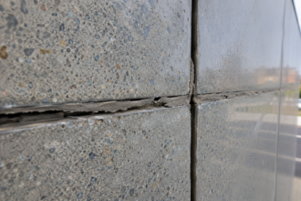
Failure Mode 3 is sealant joint design failure at dissimilar material interfaces. EIFS terminating against aluminum storefront framing or a masonry base requires a properly sized sealant joint with backer rod and a sealant selected for compatibility with both substrates.
Joints sized too narrow cannot accommodate differential movement. A sealant joint at an aluminum storefront frame must account for the differential thermal movement between the aluminum and the EIFS assembly across the full temperature range of the project climate.
In a northern climate, that movement range can exceed the design capacity of a joint sized at 3/8 inch. Sealant selected without verifying adhesion to the EIFS base coat will fail cohesively under cycling.
ASTM E2570 provides the test method for evaluating WRB coatings used with EIFS; analogous compatibility verification applies to sealant selection. Submitting a sealant product data sheet is not the same as verifying adhesion performance to the specific base coat product in the assembly.
Failure Mode 4 is inspection gap during installation. Base coat thickness below the manufacturer-published minimum of 3/32 inch over mesh, mesh lapping deficiencies below the requirements referenced in ASTM C1063 and weep screed blockage from finish coat overspray are all field execution failures that third-party inspection catches and self-inspection misses.
These are not exotic problems. They appear on projects with experienced applicators.
A base coat applied at 1/16 inch over mesh in a high-exposure coastal location will show impact damage and water infiltration within three to five years. The applicator who installed it may have applied EIFS correctly on a hundred previous projects.
Inspection pressure at defined checkpoints changes the outcome. The absence of that pressure does not.
Specifying the WRB and Drainage Plane: Decisions That Determine System Outcome
WRB selection in an EIFS assembly is not a generic housewrap decision. Fluid-applied membranes offer superior continuity at irregular substrates and complex geometry, but compatibility with EPS adhesive chemistry requires verification before specification.
Some fluid-applied WRB products experience adhesion degradation when exposed to the solvent components in certain EPS adhesive formulations and that degradation is not visible at the time of application. It appears as delamination months later, after the EIFS is fully installed.
Self-adhered sheet membranes provide reliable lap performance but demand substrate flatness that commercial sheathing installations do not always deliver. Out-of-plane sheathing at stud bays creates bridging conditions where the self-adhered membrane spans rather than bonds and that unbonded span becomes a water migration path when the membrane is punctured.
Mechanically fastened housewraps are the most forgiving of substrate irregularity but create fastener penetrations that require careful detailing at every point.
Drainage mat selection carries assembly thickness implications. A three-dimensional drainage mat adds measurable thickness to the assembly and provides higher drainage rate performance under sustained water load.
Grooved EPS back-cut drainage channels reduce assembly thickness but perform differently under high-volume water entry events. Neither is universally superior; the selection depends on climate zone, expected exposure and wall assembly thickness budget.
On a project where the window-to-wall interface is already constrained by storefront system depth, adding a drainage mat thickness may require revision to the window rough opening dimensions. That coordination needs to happen at the design phase, not during shop drawing review.
The project manual must assign WRB continuity obligations explicitly. Division 07 specifications should name the responsible party for flashing integration at rough openings without ambiguity.
When the fenestration installer and the EIFS applicator are separate subcontractors with overlapping scope at the window head, claims happen at that interface. Write the responsibility into the specification before the bid, not into the change order after the leak.
A specification that reads “coordinate with adjacent trades” at the window head flashing detail is not a specification. It is a liability transfer document waiting for a moisture event to activate it.
Substrate specification is not optional language. Standard gypsum board per ASTM C36 is not acceptable as an EIFS substrate in commercial applications.
Specify ASTM C1177 or ASTM C1278 products explicitly and verify submittals before sheathing installation begins. If the submittal log shows a C36 product substituted for a C1177 product, reject it at the submittal stage.
Catching that substitution after the sheathing is installed and the EIFS applicator is mobilized costs significantly more than the margin the substitution was intended to recover.
Transition Detailing at the Interfaces That Generate the Most Claims
Window and door head flashing is the single highest-frequency claim location in commercial EIFS assemblies. Through-wall flashing with end dams is the correct detail.
The integration sequence is specific: flashing laps over the WRB below and the WRB laps over the flashing above. Reversing this sequence directs water into the wall assembly rather than out of it.
Sealant-only terminations at the window head are a specification error. They are also still appearing in construction documents from firms that should know better.
The end dam at the flashing termination is not a minor accessory; it is the element that prevents water from tracking laterally off the flashing end and into the wall cavity at the jamb condition. Omitting the end dam on a through-wall flashing is the equivalent of installing a gutter with an open end.
The flashing collects water and delivers it to the wall rather than away from it.
Horizontal terminations at floor-line reveals, expansion joints and base conditions require minimum clearance above grade and positive slope to drain. Sealant joint sizing at these locations must account for differential movement between the EIFS assembly and the adjacent substrate.
ASTM C1382 provides the test method for tensile adhesion of sealants used in EIFS joints; specifying sealant products without verifying performance to this standard is an exposure the project does not need. Floor-line reveals on multi-story commercial buildings are a particularly common failure location because the reveal creates a horizontal surface that collects water and directs it toward the sealant joint at the back of the reveal.
That joint must be sized, backed and sealed to a higher standard than a field joint in a vertical plane, because the water load it manages is higher and the drainage path if it fails is directly into the wall assembly.
The roof-to-wall transition generates disproportionate claim frequency relative to its linear footage. EIFS carried above a parapet requires counterflashing integration and positive drainage away from the EIFS termination.
EIFS terminated below roofing requires a counterflashing that protects the top edge of the EPS from sustained water contact. Crickets at equipment curbs and parapet corners are not optional geometry; they are drainage infrastructure.
A parapet corner without a cricket on a low-slope roof accumulates standing water at the EIFS base condition after every rain event. The EPS at that location is not designed for sustained immersion.
The failure timeline at an unprotected parapet corner base is measured in years, not decades.
Penetrations are the inspection checkpoint that field crews most consistently skip. Pipes, conduit and mechanical equipment supports penetrating the EIFS assembly require annular sealant detailing with appropriate backing.
The backing must be sized to support sealant tooling. An unsupported sealant bead at a pipe penetration will fail under thermal cycling within a few years.
On mechanical equipment supports, the penetration geometry is often irregular and the backing installation is difficult, which is precisely why field crews skip it. The inspection hold at penetration detailing completion, before finish coat application covers the work, is the only reliable way to verify that the backing and sealant are installed correctly.
After the finish coat is applied, the penetration detail is invisible and the only way to evaluate it is to remove material.
The Specification-to-Field Gap and How to Close It
The performance gap in EIFS assemblies is not primarily a materials problem. Current drainage EIFS products, when specified correctly and installed to published tolerances, perform reliably across a wide range of commercial applications.
The gap is between what the specification requires and what field crews actually install and that gap is widest at the transition details described above.
Third-party special inspection at defined checkpoints is the most direct way to close this gap. Specify inspection holds at WRB installation completion, at fenestration rough opening flashing completion before fenestration installation and at base coat application before finish coat application.
These are not burdensome requirements. They are the same inspection discipline applied to any other weather-resistive assembly on a project with meaningful moisture risk exposure.
A fourth inspection hold at penetration detailing completion, before finish coat application, adds minimal project schedule impact and closes the most consistently skipped field execution checkpoint. The inspector at these holds is not reviewing paperwork.
The inspector is verifying that the WRB laps are correctly oriented, that the flashing end dams are installed, that the base coat thickness meets the manufacturer minimum and that the weep screed is clear of finish coat overspray. Each of those items is verifiable in the field in minutes.
Each of them, when missed, produces a moisture pathway that operates for the life of the building until a failure investigation exposes it.
Pre-installation meetings that include the EIFS applicator, the fenestration installer and the waterproofing subcontractor together in the same room, reviewing the transition details at window heads and horizontal terminations before work begins, reduce coordination failures at those interfaces. That meeting does not replace inspection holds.
It reduces the frequency of conditions that inspection holds need to catch. The combination of pre-installation coordination and defined inspection holds is the specification and construction administration practice that the forensic record supports.
Projects that include both have a demonstrably different moisture performance history than projects that include neither.
The owner who bans EIFS after a barrier system failure from 1997 is making a specification decision based on a system that no longer exists in the commercial market. The correct response to that failure investigation is a specification that requires drainage EIFS per ASTM E2568, moisture-resistant substrate per ASTM C1177 or C1278, WRB continuity obligations assigned without ambiguity in Division 07 and third-party inspection at the four checkpoints above.
That specification produces a different outcome. The evidence from properly detailed installations across Climate Zones 4 through 7 supports that conclusion.
The litigation history that drives insurance exclusions does not.