EIFS Under Pressure: Understanding Drainage Mat Performance and Water Management Failures in Barrier vs. Drainage Wall Assemblies
Three years after a mid-rise mixed-use project in Charlotte, North Carolina reached substantial completion, the owner’s attorney was reviewing a $2.1 million construction defect claim. The investigation found widespread staining, soft spots in the substrate and active mold growth behind the EIFS cladding on the wood-framed upper floors.
A drainage EIFS system had been specified. The drainage mat was omitted at the base of wall transitions.
Flashing terminations were sealed directly against the base coat rather than integrated with the drainage plane. The EIFS did not fail.
The assembly failed because no one on the project treated it as a coordinated system.
That distinction matters legally as much as it matters technically.
Barrier vs. Drainage EIFS: The Distinction That Defines Liability
Barrier EIFS relies on the finish coat as the sole line of defense against water intrusion. There is no designed drainage path behind the insulation board.
Water that bypasses the finish system at penetrations, joints or terminations has nowhere to go. It accumulates against the substrate.
Drainage EIFS incorporates a drainage plane between the insulation board and the substrate. That plane takes the form of an entangled polymer mat, grooved EPS insulation or a drainage board assembly.
Its function is to provide a managed exit path for incidental water that defeats the finish coat. This is not a belt-and-suspenders upgrade.
It is a fundamentally different assembly logic.
The litigation history of barrier EIFS in the 1990s and early 2000s is not ancient history to the attorneys handling today’s defect claims. The North Carolina class action settlements and the documentation assembled by the Synthetic Stucco Awareness Network established a clear record: barrier EIFS applied over wood-framed construction in humid and mixed climates produced systemic substrate damage at rates that could not be explained by installation error alone.
The physics of the assembly were the problem.
That history produced code language. IBC Section 1403.2 establishes the general weather protection requirement for exterior walls.
IBC Section 1408.4.1 is more specific: drainage EIFS is mandatory for wood-framed construction. This is not a best practice preference.
It is a code requirement and it has been for multiple IBC cycles.
What the code does not specify is how drainage EIFS must be detailed at transitions, penetrations and terminations. That gap between the mandatory product category and the mandatory execution method is where most defect claims originate.
A project team that specifies drainage EIFS and stops there has satisfied the minimum code trigger without addressing the conditions that determine whether the drainage plane actually functions. The specification must carry the assembly logic further than the code does or the code compliance on paper produces a non-performing assembly in the field.
Attorneys reviewing defect claims understand this distinction. Expert witnesses in EIFS litigation routinely distinguish between code-compliant product selection and code-compliant assembly performance and those are not the same finding.
Why Barrier EIFS Failed: Climate, Physics and the Limits of Monolithic Cladding
The moisture accumulation mechanism in barrier EIFS is straightforward. Water infiltrates at penetrations, joints and terminations.
The finish coat is impermeable. The insulation board is impermeable.
The assembly traps moisture between two impermeable layers with no exit path. In humid and mixed-humid climates, vapor pressure differentials and hygrothermal cycling drive that moisture deeper into the assembly over time rather than allowing it to dissipate.
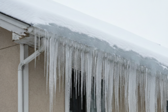
ASHRAE climate zones 3 through 5 cover the majority of North American construction volume. These zones include the mixed-humid Southeast, the mid-Atlantic, the Great Lakes region and the Pacific Northwest.
In these zones, the direction of vapor drive reverses seasonally. An assembly that dries in summer may rewet in winter.
Barrier EIFS provided no mechanism for either drying direction to function.
OSB and wood-based sheathing are particularly vulnerable. Prolonged moisture exposure above 19 percent moisture content by weight initiates fungal growth.
Documented barrier EIFS failures showed structural degradation of sheathing and framing within two to five years of installation. The substrate did not fail because of poor lumber grades or substandard OSB.
It failed because the assembly held moisture against it continuously.
Barrier EIFS is not universally defective. Arid IECC climate zones 2B and 3B showed far fewer failures because the drying potential of those climates is high enough to manage incidental moisture even without a drainage plane.
The problem is that North American construction is concentrated in zones where that drying potential does not exist. ASTM E2568, the governing product standard for PB exterior insulation and finish systems, does not mandate drainage but establishes performance criteria that drainage assemblies are demonstrably better positioned to meet in high-exposure conditions.
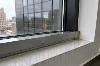
The hygrothermal research that followed the barrier EIFS litigation wave reinforced what the failure data had already shown. Oak Ridge National Laboratory and the Building Science Corporation published field monitoring data from instrumented wall assemblies in the late 1990s and early 2000s that quantified moisture accumulation rates in barrier configurations.
Those studies showed that even minor water entry events at window perimeters, less than what would be visible as active leakage, produced moisture content readings in sheathing that exceeded the fungal growth threshold within weeks in climate zone 4 conditions. The assembly did not need to fail catastrophically to produce substrate damage.
It needed only to trap small amounts of water repeatedly, which is exactly what barrier EIFS does by design.
How Drainage EIFS Is Supposed to Work: The Assembly Logic
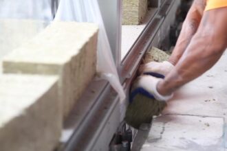
A properly designed drainage EIFS assembly functions through three interdependent layers. The weather-resistive barrier applied to the sheathing provides the primary water control layer.
The drainage plane component creates an air gap or capillary break between the WRB and the insulation board face. The EIFS lamina, comprising base coat, reinforcing mesh and finish coat, provides the exterior face.
The drainage plane does not prevent water entry. It manages water that enters.
Water that bypasses the finish coat at any point drains down through the drainage gap and exits at the base of wall through weep screeds or open reveals. This is the designed behavior.
The drainage gap is a feature, not a defect.
The WRB and drainage mat are interdependent in ways that specifiers sometimes underestimate. A correctly installed WRB without a functional drainage mat still traps water against the insulation board face because the insulation board itself is impermeable.
The water control layer and the drainage plane must both perform for the assembly to function as designed. Failure of either component compromises both.
The EIMA Guideline Specification for Drainage EIFS defines minimum drainage gap requirements and establishes compatible WRB types. It is not a substitute for project-specific detailing, but it provides the baseline performance criteria that specifications should reference explicitly rather than leaving drainage gap dimensions and WRB compatibility to field judgment.
The WRB selection decision carries more consequence than many specifications acknowledge. Fluid-applied WRBs, self-adhered sheet membranes and mechanically attached housewraps each interact differently with drainage mat products.
A fluid-applied WRB that bridges the drainage mat fasteners or fills the mat profile at attachment points reduces the effective drainage gap at those locations. A housewrap with low vapor permeance installed in a climate zone where inward vapor drive is significant during summer months can trap moisture between the WRB and the sheathing even when the drainage mat is performing correctly.
ICC-ES AC219 provides acceptance criteria for drainage EIFS products and includes WRB compatibility requirements that should be confirmed against the specific WRB product being used, not assumed based on generic material category. Specifiers who treat WRB selection as a separate decision from drainage mat selection are designing the two components in isolation when the assembly requires them to be designed together.
Drainage Mat Selection: Where Specifications Go Wrong
Drainage mat selection is where technically sound specifications most frequently break down in practice. Three primary mat types are available: entangled polymer mats (dimple mat configurations), grooved EPS insulation boards and drainage boards with integrated WRB.
Each has different flow capacity, compressibility behavior under base coat application pressure and compatibility with adhesive versus mechanical attachment methods.
The compressibility problem is underappreciated. Entangled polymer mats compress under the pressure applied during base coat application.
A mat specified at a nominal drainage gap of 3/8 inch may perform at a fraction of that gap after installation. If the mat selection does not account for the application method and the pressure it generates, the drainage gap the specification requires may not be the drainage gap that exists in the finished assembly.
Flow rate capacity relative to expected water load is equally important. Not all drainage mats drain at equivalent rates.
A mat with insufficient flow capacity in a high-exposure assembly, one with large uninterrupted cladding areas or significant wind-driven rain exposure, will allow water to pond behind the insulation rather than drain. The drainage plane becomes a retention layer.
This is worse than no drainage plane because it holds more water in contact with the WRB for longer periods.
Adhesive attachment compatibility requires explicit confirmation. Some entangled mats are incompatible with full-coverage adhesive application of insulation boards because the adhesive bridges or fills the drainage gap.
The specification must confirm that the attachment method and the drainage mat are compatible before the project reaches the field.
Manufacturer substitution in the field is a documented source of drainage failures that does not appear in the design record. A specified mat gets substituted for an available alternative.
The substitution is not flagged as a material change. The replacement mat has different compressibility characteristics or lower flow capacity.
The assembly underperforms. ASTM E2273, the standard test method for determining the drainage efficiency of exterior insulation and finish system clad wall assemblies, provides the quantitative basis for comparing mat performance.
Project teams should request E2273 test data for the specific mat being installed, not generic product literature that may reference a different mat configuration or installation method.
The grooved EPS option addresses the compressibility problem differently than entangled polymer mats. Because the drainage channels are cut into the insulation board face rather than provided by a separate mat layer, there is no compressible intermediate component.
The drainage gap dimension is fixed by the groove depth and does not change under base coat application pressure. The tradeoff is that grooved EPS requires more careful attention to vertical alignment of the grooves and to the continuity of the drainage path at board joints.
A grooved EPS board installed with the grooves running horizontally provides no vertical drainage path. That installation error is not immediately visible and does not appear in any inspection record until moisture damage surfaces years later.
The specification should require groove orientation confirmation as part of the pre-installation conference agenda, not leave it to the applicator’s judgment.
Flashing Integration: The Most Commonly Misdetailed Interface
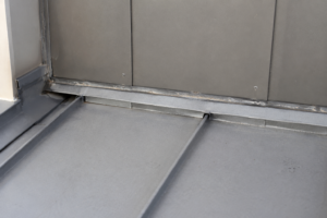
Flashing failures account for a disproportionate share of drainage EIFS moisture claims. The Charlotte project described at the opening is representative.
Flashing was present. It was simply terminated against the base coat rather than integrated with the drainage plane.
Water that entered above the flashing had no path to the drainage gap. It tracked laterally behind the insulation and accumulated at the base of wall transition.
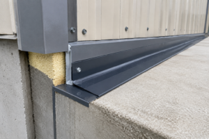
The critical flashing locations in a drainage EIFS assembly are the base of wall, window and door heads, sill pans, penetration collars and any horizontal ledger or shelf angle condition. Each of these locations requires the flashing to connect to the WRB and terminate in a way that directs water into the drainage gap rather than trapping it between the flashing and the insulation board face.
Sill pan flashing is where the specification-to-field gap is most consequential. The pan must slope to drain, must connect to the WRB on both jambs and must terminate at the face of the drainage mat so that water exits through the drainage gap rather than accumulating in the pan.
A sill pan that terminates at the base coat face has no functional connection to the drainage plane. It is a collection device, not a drainage device.
Fenestration rough openings in EIFS assemblies require sequenced installation. The WRB must be installed and lapped before the drainage mat is applied.
The drainage mat must be cut and terminated at the rough opening in a way that maintains the drainage gap to the weep screed at the sill. Base coat application cannot bridge the drainage mat termination at the sill.
These sequences are not complicated. They require coordination between the WRB installer, the fenestration installer and the EIFS applicator that rarely happens without explicit requirements in the project documents.
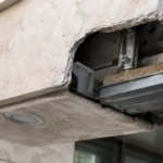
Shelf angle and horizontal ledger conditions present a flashing geometry problem that standard details frequently mishandle. Water that enters above a shelf angle must be directed outward past the face of the angle and into the drainage gap below.
A flashing that terminates at the back leg of the shelf angle collects water at the angle rather than shedding it. The correct termination brings the flashing leg out past the drainage mat face and turns it down so that water drips free of the assembly.
This detail requires coordination between the structural steel installer and the EIFS applicator because the flashing cannot be installed correctly after the insulation board is in place. When that sequencing is not enforced in the project schedule, the flashing gets installed after the insulation board and the termination geometry defaults to whatever fits in the remaining space, which is typically not what the detail requires.
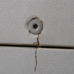
Penetration collars at pipe, conduit and mechanical equipment locations are frequently treated as sealant-only conditions in EIFS assemblies. The sealant terminates at the base coat face and the drainage plane behind the insulation board is not addressed.
Water that enters at the penetration collar tracks behind the insulation board and has no exit path unless the collar flashing is integrated with the drainage mat. Pre-manufactured penetration collar flashings with drainage mat integration tabs are available from several manufacturers and eliminate the field fabrication problem at these locations.
Specifying them by name rather than leaving penetration collar treatment to field judgment reduces the probability of a sealant-only condition being installed.
Base Coat Application and the Drainage Gap: A Detail That Defeats the System
The base coat is the component most likely to inadvertently compromise the drainage plane during installation. Applied too heavily at terminations, it fills the drainage gap.
Applied without attention to the mat termination condition at weep screeds, it blocks the exit path that the drainage plane is designed to provide.
Weep screed detailing is the terminal condition for the entire drainage assembly. The drainage gap must remain open at the weep screed.
The base coat must terminate above the weep screed’s drainage apertures, not across them. This is a detail that looks correct from the face of the assembly and fails completely from behind it.
Field inspection at this condition requires looking at the back of the weep screed during installation, not after the finish coat is applied.
Mesh embedding depth affects base coat thickness at terminations. Overdriving the mesh into the base coat to achieve a smoother finish surface increases base coat thickness.
At drainage mat terminations, that additional thickness fills the gap. Applicators trained primarily on barrier EIFS systems do not have ingrained habits around protecting the drainage gap because barrier EIFS has no drainage gap to protect.
This is a training gap that specifications cannot fully compensate for, but pre-installation conferences that walk through the drainage gap protection requirements explicitly can reduce it.
The base coat mixing ratio is a contributing variable that field supervision rarely monitors. A base coat mixed with excess water to improve workability in hot weather conditions has lower viscosity and flows more readily into the drainage mat profile before it sets.
The applicator achieves easier application and the drainage gap fills more completely than it would with a properly proportioned mix. Manufacturer published mixing ratios are not suggestions.
They establish the viscosity range that keeps the base coat from migrating into the drainage mat. Requiring batch tickets and mix ratio documentation as a submittal item gives the project record something to reference when the drainage gap condition is disputed later.
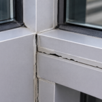
Corner and termination conditions at control joints present a specific base coat management problem. Control joints in drainage EIFS assemblies must maintain the drainage gap continuity through the joint.
A control joint backer that bridges the drainage mat without maintaining the gap converts the control joint into a dam. Water that reaches the control joint from above accumulates rather than continuing to drain.
The EIMA detail library includes control joint configurations that maintain drainage gap continuity and those details should be referenced explicitly in the specification rather than leaving control joint treatment to the applicator’s standard practice, which may be based on barrier EIFS experience where gap continuity is not a consideration.
What the Next Failure Will Look Like
The next significant EIFS drainage failure on your project will not announce itself at year one. It will present at year three or four as staining at the base of wall, soft spots at sill conditions and a finish coat that sounds hollow when tapped.
By the time those signs appear, the WRB has been wet for two years and the sheathing is approaching the moisture content threshold for fungal growth.
The specification is the last point at which the entire assembly can be treated as a coordinated system rather than a collection of independent products. Require ASTM E2273 test data for the specified drainage mat.
Require compatibility confirmation between the mat and the attachment method. Require sequenced installation at fenestration rough openings and base of wall transitions.
Require pre-installation conferences that address drainage gap protection explicitly.
IBC Section 1408.4.1 tells you drainage EIFS is mandatory on wood-framed construction. It does not tell you how to keep the drainage gap open through base coat application or how to connect a sill pan flashing to a drainage mat termination.
That gap between the code requirement and the executed detail is where the $2.1 million claims originate.
The forensic investigation pattern in EIFS defect claims is consistent enough that it functions as a checklist for what the specification should have required. Investigators find drainage mats that were compressed to non-functional gap dimensions.
They find sill pan flashings that terminate at the base coat face. They find weep screeds blocked by base coat overapplication.