Brick Veneer on Steel-Stud Backup Walls: Tie Spacing, Differential Movement and the Structural Failures That Don’t Show Up Until Year Ten
The Failure Pattern Nobody Saw Coming
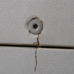
A forensic investigation on a 12-year-old, four-story medical office building in the Mid-Atlantic region reveals a pattern that has become grimly familiar: corroded, bent and partially disengaged wire ties behind a brick veneer facade that shows only hairline cracking at the sill line and minor efflorescence at the third-floor band course. The building owner assumed the facade was performing.
The ties had been failing progressively since year four.
By the time water intrusion reached interior finishes, an estimated 340 linear feet of veneer had lost meaningful structural engagement with the steel-stud backup wall. The exterior presented no dramatic signals.
No spalling. No bulging.
No displaced coursing. Just the kind of minor cosmetic distress that property managers attribute to normal aging and defer to the next capital cycle.
That deferral cost the owner a full veneer remediation in year twelve that would have cost a fraction of the price in year six, if anyone had been looking at the right things.
This is not an unusual story. It is the predictable outcome of a system that gets specified frequently, detailed inadequately and inspected almost never.
The medical office building case is representative of a broader pattern documented across commercial construction in the Mid-Atlantic, Great Lakes and Pacific Northwest regions, where seasonal temperature swings and sustained moisture exposure accelerate the degradation mechanisms that inadequate specifications allow to begin. The building in question had been reviewed by its property management team on an annual basis.
None of those reviews included cavity access. None of them would have caught what was happening behind the brick.
Why Anchored Brick Veneer on Steel Studs Is Not the Same System as Brick on Masonry Backup
Practitioners who cut their teeth on traditional brick-on-CMU construction sometimes carry assumptions about veneer behavior that do not transfer to steel-stud backup assemblies. The behavioral differences are fundamental, not marginal.
Masonry-on-masonry backup shares stiffness and thermal mass across both wythes. The backup wall participates in resisting lateral load and both elements move in similar thermal patterns.
Steel-stud backup is flexible, thermally responsive and subject to independent deflection under both lateral wind load and gravity. It does not behave as a monolithic substrate.
Each stud deflects independently of the veneer plane and the gap between the two systems is not fixed; it is dynamic, changing with load and temperature.
The veneer is a non-loadbearing cladding. That classification matters because it means the tie system carries the entire structural relationship between the veneer and the building.
There is no redundancy. Tie failure is not gradual aesthetic degradation; it is progressive structural detachment.
IBC Section 1405.6 establishes the distinction between anchored veneer and a structural wythe explicitly and that distinction should inform every decision made about tie selection, spacing and corrosion protection. The scope here is commercial construction governed by IBC, with tie systems specified to ASTM standards.
What makes the steel-stud system particularly unforgiving is that its flexibility is not visible from the outside and is rarely modeled accurately in the design phase. A CMU backup wall at 8-inch nominal thickness has a moment of inertia that is orders of magnitude greater than a 6-inch, 18-gauge steel stud at 16-inch spacing.
The stud wall will deflect under design wind pressure in ways that the CMU wall simply will not and that deflection is transferred directly to the tie geometry. Practitioners who have not worked through the deflection calculations for a steel-stud backup wall under AISI S100 often underestimate how much the tie is actually being asked to do.
The tie is not a passive connector. It is an active structural element in a system with two independently moving components and it needs to be specified and inspected accordingly.
The Mechanics of Steel-Stud Deflection and What It Does to Tie Geometry
Steel studs deflect under lateral wind load in a parabolic curve. The veneer, being a rigid plane, does not deflect in the same profile.
The tie must bridge an increasingly non-perpendicular gap as deflection increases toward midspan, which means the tie is not simply in tension; it is in combined tension and bending, with the bending moment concentrated at the embedment point in the mortar joint.
IBC and AISI S100-16 Section C3.1 limit stud deflection to L/600 for backup walls supporting masonry veneer. That limit exists because the tie geometry problem becomes structurally significant beyond it.
Value-engineering routinely substitutes lighter gauge studs or wider stud spacing that pushes deflection toward L/360, which is the limit appropriate for interior partitions. These are not equivalent.
At L/360 deflection, a wire tie at midspan of a 12-foot stud is accommodating approximately 0.4 inches of out-of-plane displacement while simultaneously resisting in-plane shear from veneer self-weight. That combined loading condition is not what standard wire ties are tested for under ASTM E72, which evaluates structural performance of panel systems but does not replicate dynamic or cyclic tie loading in combination.
The initiation mechanism for fatigue failure is tie bending at the mortar embedment point. Repeated wind cycling accelerates this even when individual deflection events appear within tolerance.
A tie that survives a single design wind event may accumulate fatigue damage across a hundred smaller events over three years. By year eight, the wire has work-hardened and cracked at the bend.
The veneer is still standing. The tie is not doing what anyone thinks it is doing.
To put numbers to this: a 3/16-inch diameter wire tie embedded 1.5 inches into a mortar joint and attached to a stud that deflects 0. 4 inches at midspan is experiencing a bend angle of approximately 1.9 degrees at the embedment point under each wind event.
That angle is small enough that no field inspector would detect it visually. Repeated across several hundred wind loading cycles per year, the wire accumulates plastic strain at the bend.
Standard wire ties are not manufactured to a fatigue life specification. ASTM A1008 governs the base material, but there is no ASTM standard that requires fatigue testing of wire ties under combined tension and bending loads representative of actual service conditions.
The published load ratings from manufacturers reflect static pull-out tests, not cyclic service loading. That gap between rated capacity and actual service performance is where the failure lives.
This is where the specification-to-field gap becomes a structural liability rather than a quality issue.
Thermal Differential Movement: The Variable Nobody Calculates on Site
Fired clay brick has a coefficient of thermal expansion of approximately 3.6 x 10 to the negative sixth power per degree Fahrenheit. Steel sits at approximately 6.5 x 10 to the negative sixth power per degree Fahrenheit.
Over a 100-degree Fahrenheit seasonal temperature swing across a 30-foot facade panel, that differential produces movement exceeding 3/8 inch. The two materials are trying to occupy different positions in space and the tie system is the only thing connecting them.
The solar loading condition makes this worse. A dark brick surface on a south-facing facade can reach 150 degrees Fahrenheit on a 90-degree day.
The steel backup behind continuous insulation remains near ambient. The veneer is expanding aggressively while the backup wall is not.
The tie must absorb this differential in shear, simultaneously with whatever wind load is present. This is not a design edge case.
This is a routine summer afternoon in IECC Climate Zones 4 through 6.
Horizontal expansion joints in brick veneer exist specifically to relieve this movement. BIA Technical Note 18A recommends joints at every floor line and at maximum 20-foot vertical intervals.
Forensic investigations routinely find these joints omitted, filled with mortar during construction or located incorrectly relative to shelf angles. When the joints are absent, the movement the joint was supposed to absorb goes somewhere else.
It goes into the tie. MSJC TMS 402/602 Section 6.2.2 establishes movement joint requirements for anchored veneer, but specification compliance at the construction document phase does not guarantee field execution.
The cumulative effect is ties placed in permanent tension or shear bias rather than the neutral condition assumed in their published load ratings. Rated capacity under idealized test conditions is not the same as effective capacity under real service conditions.
What makes this particularly difficult to catch during construction is that the movement joint problem is invisible at the time of installation. A mason who fills a horizontal expansion joint with mortar is not creating an obvious defect.
The joint looks like every other joint. The sealant that should occupy the lower portion of the joint is either never installed or is installed over a mortar bed that prevents it from functioning.
The building passes inspection. The facade looks correct.
The movement that will eventually load the ties to failure has not yet occurred because the building has not yet experienced its first full seasonal temperature cycle. By the time the first cycle completes, the joint is inaccessible and the condition is locked in.
Tie Spacing Requirements Versus Field Reality
IBC 2021 Section 1405.6.2 requires anchored veneer ties at maximum 32 inches horizontally and 18 inches vertically, with a maximum tributary area of 2. 67 square feet per tie.
These are code minimums. They are not engineered optima and treating them as design targets rather than floors is a common specification error.
MVMA guidelines and BIA recommendations call for reduced spacing in high-wind zones, at corners and within 8 feet of openings. These refinements are the first items removed during value engineering because they add material cost and installation time without producing a visible change in the finished facade.
The result is a code-compliant specification that performs at the bottom of the acceptable range under ideal conditions and below it under actual service conditions.
Field observation reveals a consistent pattern: ties installed at 16-inch stud spacing are often placed only at stud locations, creating an effective horizontal spacing of 32 inches even when the specification calls for 16 inches. Inspectors rarely verify tie count against tributary area calculations because that verification requires counting ties in a cavity that is already closed.
Corrosion-resistant coating requirements compound the problem. ASTM A153 hot-dip galvanizing is the appropriate specification for wire ties in wet cavity conditions.
Mechanically galvanized and epoxy-coated alternatives are frequently substituted; they perform differently in sustained moisture exposure and their service life in a poorly drained cavity is materially shorter.
The substitution problem is not limited to the field. It begins in the submittal review process, where mechanically galvanized ties are submitted against a specification requiring hot-dip galvanizing and approved without comment because the reviewer is not checking coating type against the ASTM designation.
Mechanical galvanizing per ASTM B695 produces a coating that is adequate for dry or intermittently wet conditions but degrades significantly faster than hot-dip galvanizing per ASTM A153 in the sustained wet conditions that exist in a cavity wall with inadequate drainage. The coating thickness minimums differ: ASTM A153 Class B requires 1.0 oz per square foot minimum, while ASTM B695 Class 50 requires approximately 0.
7 oz per square foot. That difference in coating mass translates directly to service life in a wet cavity.
A tie that should last 25 years under ASTM A153 may show significant corrosion in 10 to 12 years under ASTM B695 in the same conditions. That timeline maps directly onto the forensic pattern described at the opening of this article.
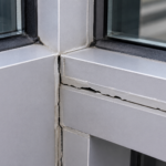
Corner and opening conditions deserve specific attention. The 8-foot zone adjacent to window and door openings concentrates stress because the veneer panel terminates at the opening and the tie at the termination point carries the full lateral load of the panel edge without the load-sharing that occurs in the field of the wall.
Specifications that call for reduced tie spacing in these zones are technically correct. The problem is that the mason laying brick at a window corner is working from a tie layout that was marked on the sheathing before the window was framed and the as-built opening location rarely matches the drawing location precisely enough to preserve the specified tie pattern at the jamb.
The result is ties that are either missing entirely at the critical edge zone or placed at the wrong height relative to the mortar joint.
The Water Control Layer Nobody Treats as Continuous
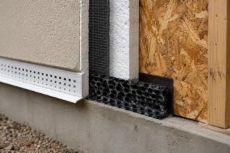
The air and water control layers in a steel-stud backup assembly are typically the WRB applied to the sheathing face, with the cavity serving as a drained (not ventilated) air space. The distinction between a drained cavity and a ventilated cavity matters here: a drained cavity relies on gravity to remove water that penetrates past the veneer, while a ventilated cavity uses airflow to accelerate drying.
Most brick veneer assemblies on steel studs are designed as drained cavities, which means weep openings at the base of each story are the primary water control mechanism.
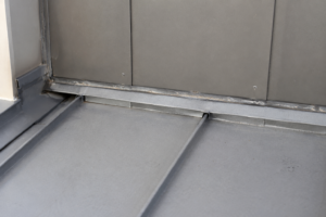
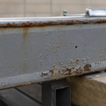
When weeps are omitted, spaced incorrectly or filled with mortar during construction, water accumulates at the shelf angle. That water contacts the wire ties at their most vulnerable location: the point where the tie penetrates or contacts the backup assembly.
Galvanic corrosion accelerates when dissimilar metals are in contact in the presence of moisture and the combination of steel ties, galvanized shelf angles and aluminum through-wall flashing components creates exactly that condition if the assembly is not detailed to keep them separated and dry.
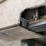
The four control layers (water, air, vapor and thermal) all intersect at the shelf angle and the shelf angle is where most assemblies fail to maintain continuity in any of them. Thermal bridging at the shelf angle is well-documented; the effective R-value of the assembly at that location drops sharply regardless of how much continuous insulation is specified in the field of the wall.
The weep opening problem is more specific than it appears in most specifications. Standard open-head joint weeps at 24-inch spacing are the default detail in most project documents.
That spacing is adequate for a cavity that drains freely. In practice, mortar droppings accumulate at the base of the cavity during brick installation and partially or fully block the drainage path.
The mortar does not need to completely fill the cavity to redirect water. A mortar bridge that spans from the back of the veneer to the face of the WRB at the shelf angle creates a capillary path that draws water directly to the tie attachment point and holds it there.
Cavity drainage mats or mortar collection devices at the base of the cavity address this, but they appear in specifications far less frequently than the problem warrants.
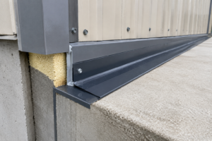
Through-wall flashing at the shelf angle is the other critical detail. The flashing must extend from the back of the cavity to the face of the veneer and turn down to form a drip edge.
End dams at each shelf angle segment are required to prevent water from migrating laterally past the flashing termination. Forensic investigations consistently find flashing that terminates short of the veneer face, end dams that were never installed and lap joints in the flashing that were not sealed.
Each of these conditions allows water that reaches the shelf angle to bypass the flashing entirely and accumulate in the cavity rather than being directed to the weep openings. The tie corrosion that results is not a material failure.
It is a detailing and execution failure that the material cannot compensate for regardless of its coating specification.
What a Condition Assessment Should Actually Look For
A peer review of a brick veneer specification or a condition assessment of an existing assembly requires looking past the visible surface. Hairline cracking at sill lines and efflorescence at band courses are lagging indicators.
By the time they appear, the underlying failure has typically been progressing for years.
Probe testing at suspect locations, infrared thermography during appropriate delta-T conditions and selective tie exposure through removed brick units are the tools that reveal actual tie condition. On the forensic project described at the opening of this article, IR imaging during a winter heating day showed clear anomalies at the third-floor band course that corresponded precisely to locations of confirmed tie failure when units were removed.
The IR data was available in year six if anyone had commissioned the survey.
Specifications should require pre-construction pull testing of installed ties per ASTM C1072 to verify embedment depth and mortar bond, not just visual inspection of tie placement. That requirement rarely appears in project specifications and almost never survives value engineering when it does.
The IR thermography protocol matters as much as the decision to use it. A delta-T of at least 10 degrees Fahrenheit between interior and exterior is the minimum condition for reliable anomaly detection in a masonry veneer assembly.
Surveys conducted in mild weather or during periods of direct solar loading on the facade produce results that are difficult to interpret and easy to dismiss. Winter heating season surveys, conducted on overcast days to eliminate solar gain as a variable, produce the clearest data.
The anomalies that correspond to tie failure zones appear as areas of elevated surface temperature on the exterior face of the veneer, reflecting the disruption of the thermal boundary at locations where the cavity condition has changed. An experienced thermographer can distinguish tie failure zones from moisture anomalies and from normal thermal bridging at shelf angles, but that distinction requires both appropriate survey conditions and a reviewer who understands what the signatures mean in the context of this specific assembly type.
Selective tie exposure should be targeted based on the IR survey results rather than conducted randomly. Removing brick units at locations flagged by thermography and at locations that appear thermally normal provides a comparison set that validates the IR interpretation.
The exposure protocol should document tie condition photographically before any cleaning or manipulation, because the corrosion pattern on the wire surface carries information about the failure mechanism. Uniform corrosion across the tie length suggests sustained moisture exposure throughout the cavity.
Concentrated corrosion at the mortar embedment point suggests cyclic wetting and drying at the joint face.