
Thermally Broken Aluminum Window-to-Curtainwall Receptor Interfaces: The Performance Gap Nobody Tests
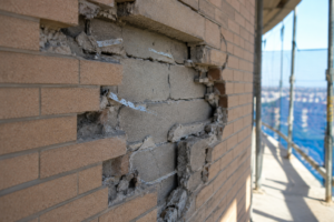
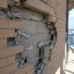
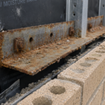
A forensic investigation on a 12-story mixed-use tower in Minneapolis reveals recurring condensation streaking along the interior sill of every punched window unit on the north and west elevations: not at the glazing edge, not at the frame, but precisely at the receptor leg where the window system terminates into the curtainwall grid. The window manufacturer’s thermal simulation shows a compliant U-factor of 0.28; the curtainwall manufacturer’s shop drawings show a compliant system boundary.
Neither document models the 1.5-inch aluminum receptor leg bridging between them. This is not an isolated failure.
It is a systemic design gap hiding in plain sight at one of the most common interfaces in commercial facade construction.
What the Receptor Actually Is: and What It’s Not
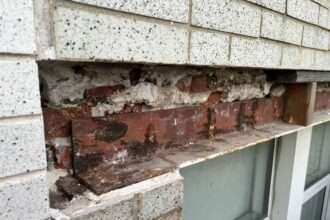
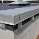
The aluminum receptor is a continuous extrusion, either site-fabricated from stock angle or supplied as a manufacturer-profiled component, that captures the window unit perimeter and mechanically anchors it to the curtainwall framing: typically a sill transom or vertical mullion. Three receptor types appear most frequently in commercial practice.
Face-fastened leg receptors use an outboard flange that laps over the window frame face. Screw-spline receptors engage a proprietary slot in the window frame perimeter.
Captured-frame receptors fully enclose the window frame perimeter in a pocket condition. Each type creates a different thermal bridge geometry, but all three share one characteristic: a continuous aluminum leg projecting from the curtainwall plane inward toward conditioned space.
The jurisdictional ambiguity around this component is a serious documentation problem. The receptor is typically specified or supplied by the window manufacturer but installed by the glazing subcontractor as part of the curtainwall scope.
The result is a submittal gap: neither the window package nor the curtainwall package fully owns the receptor condition. Shop drawings for each system stop at their respective system boundaries.
In practice, this means the receptor detail appears on the window manufacturer’s installation guide as a reference condition and on the curtainwall contractor’s shop drawings as a field-verify note. Neither document assigns thermal performance responsibility and neither document is reviewed against the other during the standard submittal process.
The general contractor’s submittal log treats them as separate line items. The architect’s review stamps each independently.
The gap between them never appears on any reviewed document.
This documentation failure has a contractual dimension that compounds the technical one. When condensation damage or energy code non-compliance surfaces during occupancy, the window manufacturer points to the NFRC system boundary as the limit of their warranty.
The curtainwall contractor points to the shop drawing boundary as the limit of theirs. The receptor, which belongs to neither boundary, belongs to neither warranty claim.
Owners and their legal counsel then discover that the component causing the damage was never assigned to a responsible party in the contract documents. That outcome is entirely predictable from the way the specifications are written and it repeats on project after project because the specification language never changes.
NFRC 100-2020 defines the simulation boundary for fenestration product U-factor testing. Field-fabricated receptor conditions fall outside that boundary by definition.
No NFRC-rated simulation for either the window or the curtainwall system includes the receptor leg. The receptor exists in a documentation no-man’s-land and that gap has thermal and moisture consequences that accumulate across every linear foot of window perimeter on a building.
The Thermal Bridge Geometry: Why Aluminum Receptor Legs Perform So Poorly
Aluminum alloy 6063-T5, the standard extrusion alloy for receptor profiles, has a thermal conductivity of approximately 200 W/m·K. Compare that to 0.04 W/m·K for closed-cell backer rod and 0.
16 to 0.25 W/m·K for typical silicone sealant. The receptor leg is not a thermal weak point.
It is a near-perfect thermal short circuit running continuously around the full window perimeter.
The typical receptor leg geometry compounds the problem. A continuous aluminum extrusion running the full perimeter of the window opening, with a leg depth of 1 to 2.5 inches projecting inward from the curtainwall plane, connects the exterior aluminum curtainwall framing directly to the interior conditioned space boundary.
In IECC Climate Zones 5 through 7, interior surface temperatures on that leg routinely fall below the dew point of typical interior air during winter design conditions. Condensation is not a risk.
It is a predictable outcome. At a Minneapolis design condition of minus 16 degrees Fahrenheit exterior and 70 degrees Fahrenheit interior at 35 percent relative humidity, the dew point of interior air is approximately 40 degrees Fahrenheit.
THERM simulations of a standard 1.75-inch aluminum receptor leg at that boundary condition consistently produce interior surface temperatures on the receptor leg face in the range of 34 to 38 degrees Fahrenheit. The condensation the forensic team observed was not a construction defect.
It was a physics result.
Thermal breaks are not standard in receptor extrusions. AAMA 505-21 (Thermal Improvement of Aluminum Framing Systems) addresses polyamide-strip and pour-and-debridge break requirements for thermally broken window frames and curtainwall members, but its scope explicitly excludes receptor conditions.
No AAMA standard mandates a thermal break at the receptor leg. No NFRC procedure captures its contribution to whole-assembly U-factor.
This exclusion is not an oversight in the standards development process so much as a reflection of the same jurisdictional ambiguity that exists in project specifications: the receptor falls between the scopes of the window standard and the curtainwall standard and neither standards committee has claimed it.
This is where linear thermal transmittance, expressed as a Ψ-value (psi-value) per ISO 10211, becomes the relevant performance metric. The receptor perimeter creates a measurable Ψ-value that is routinely omitted from whole-assembly energy models.
A 1.75-inch aluminum receptor leg on a standard punched window opening can generate a Ψ-value in the range of 0. 15 to 0.30 W/m·K depending on geometry and boundary conditions.
Summed across a full building perimeter, that omission is not a rounding error. It is a compliance gap.
A 12-story tower with 400 punched window openings averaging 6 feet wide by 5 feet tall carries approximately 8,800 linear feet of receptor perimeter. At a Ψ-value of 0.20 W/m·K, the receptor perimeter alone contributes heat loss equivalent to removing the thermal break from several hundred linear feet of curtainwall mullion.
That contribution never appears in the energy model.
The Perimeter Seal Geometry Problem: Where Water Gets In and Why
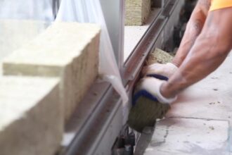
The standard receptor seal condition is a field-applied sealant bead at the receptor leg-to-window frame interface: a two-sided adhesion joint with no back-dam, no drainage path and no redundant seal plane. Glaziers apply it as a finishing bead, not as an engineered joint.
This approach fails because it violates the geometric requirements that make sealant joints durable.
Three geometric failure modes recur in forensic investigations at this interface. First, the sealant bridges across dissimilar substrates: an anodized or painted aluminum receptor leg and a thermally broken window frame with a polyamide strip at the break location.
These substrates have different thermal movement coefficients and different surface energy characteristics and the sealant bond to each behaves differently under cyclic loading. The polyamide thermal break strip in particular presents a low-surface-energy substrate that many silicone sealants do not bond to reliably without a primer and primer application at this location is almost never specified or inspected.
Second, the receptor leg deflects under wind load independently of the window frame, creating cyclic joint fatigue that a simple bead joint cannot accommodate over time. Third, the joint width-to-depth ratio at this location almost never meets the 2:1 minimum that ASTM C1193-22 requires for sealant joints subject to movement.
Glaziers typically run a 3/8-inch bead into a 3/8-inch gap, producing a 1:1 ratio that guarantees adhesion failure under thermal cycling.
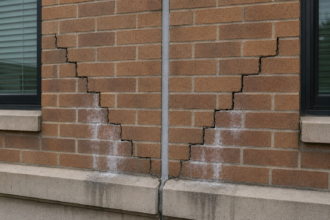
The thermal bridge condition directly worsens the seal condition. Condensation forming on the interior face of the receptor leg saturates the sealant bond line from the room side, accelerating adhesion loss at precisely the location where the joint is already geometrically compromised.
Field investigations at multiple projects in Climate Zones 5 and 6 have found sealant at the receptor-to-frame interface that has lost adhesion on the receptor leg side while maintaining apparent adhesion on the window frame side, producing a condition that passes a visual inspection from the room but fails under any probe or pull test. The sealant bead looks intact.
The bond is gone. Water and air move freely through the interface while the glazier’s punch list shows the joint as complete.
AAMA 2410-15 addresses sealant substrate compatibility at dissimilar aluminum interfaces in general terms but does not treat the receptor-to-frame joint as a distinct condition requiring its own specification. Most project specifications don’t either.
The result is a joint that fails by design. Sealant manufacturers’ technical representatives, when consulted during forensic investigations, consistently identify the same three deficiencies: wrong joint geometry, missing primer on the polyamide substrate and no back-dam to control sealant depth.
All three are specification failures, not installation failures. The glazier installed what the specification described.
What Whole-Assembly Thermal Modeling Reveals: and What It Still Misses
Current whole-assembly modeling practice under ASHRAE 90.1-2022 increasingly requires ISO 10211-compliant 2D and 3D simulation using tools such as THERM, BISCO or Flixo to capture linear thermal bridges at framing members. This is progress.
But the modeling boundary problem at the receptor interface persists even when consultants run rigorous simulations.
THERM modeling of a typical 1.75-inch aluminum receptor leg at a thermally broken window-to-curtainwall interface consistently shows an increase in the effective U-factor of the window assembly of 0. 04 to 0.09 BTU/hr·ft²·°F depending on receptor geometry and interior exposure conditions.
On a window with a rated U-factor of 0.28, that delta pushes the assembly to an effective U-factor of 0. 32 to 0.37, which exceeds the ASHRAE 90.
1-2022 Table 5.5 prescriptive limit for many climate zone and occupancy combinations. The window is compliant on paper.
The assembly is not compliant in the field. For a Class A office building in Climate Zone 6 targeting ASHRAE 90.1-2022 prescriptive compliance, the Table 5.
5 maximum U-factor for nonmetal framing fixed windows is 0.29. A receptor leg pushing the effective assembly U-factor to 0.34 represents a 17 percent exceedance of that limit on every window unit in the building.
That exceedance is invisible in the energy model submitted for permit.
Most energy consultants model the window center-of-glass and edge-of-glass conditions per NFRC 100 and stop at the system boundary. The receptor leg falls outside both the window model and the curtainwall model.
Nobody runs it. The modeling tools can handle the geometry.
THERM 7.8 and Flixo both accommodate the receptor cross-section as a straightforward 2D simulation input. The barrier is not technical capability.
It is the absence of a specification requirement that compels anyone to run the model. Without a contract requirement, the simulation does not happen and the compliance gap does not appear until a forensic investigation or a commissioning failure surfaces it.
ASHRAE 90.1-2022 Appendix NA, the normative appendix addressing linear thermal bridging, creates a framework that should capture receptor conditions in jurisdictions that have adopted the 2022 cycle, but implementation guidance for this specific interface remains underdeveloped. Jurisdictions adopting 90.1-2022 with Appendix NA will increasingly expose this gap during plan review and commissioning and the industry is not ready for that conversation.
Building departments in states that have adopted the 2022 IECC cycle, including Washington and Oregon, are beginning to ask for linear thermal bridge calculations during permit review. The receptor interface is not yet on their checklist, but the Appendix NA framework gives them the authority to require it.
When a plan reviewer in Seattle or Portland asks for a Ψ-value calculation at the receptor perimeter, the answer does not currently exist in any manufacturer’s submittal package.
Air and Vapor Control at the Receptor: The Fourth Control Layer Nobody Draws
The four control layers (water, air, vapor and thermal) must each be addressed continuously at the receptor interface and in practice, none of them is. The thermal layer failure is the most quantifiable.
The water control failure is the most visible. The air control failure is the most consequential for moisture accumulation.
Air leakage at the receptor-to-window frame joint transports orders of magnitude more moisture than vapor diffusion through the sealant. A failed sealant bead at the receptor interface creates a direct air pathway between the curtainwall cavity and the conditioned interior.
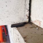
In IECC Climate Zone 6 and 7 conditions, that pathway drives warm interior air into the curtainwall cavity during winter, where it contacts cold aluminum framing and deposits moisture. The condensation the forensic team sees on the interior receptor leg surface is the visible symptom.
The concealed moisture accumulation in the curtainwall cavity is the structural and durability problem. Aluminum framing does not corrode in the same way steel does, but fasteners, anchors and embedded steel components within the curtainwall cavity are susceptible to accelerated corrosion when exposed to sustained condensation cycling.
Insulation within the cavity loses R-value when wet. Sealant bonds at the curtainwall system joints degrade under repeated wetting and drying cycles.
The receptor air leakage failure that appears as a cosmetic condensation streak on the interior sill is simultaneously driving concealed deterioration that a building owner will not discover until a facade investigation or a water intrusion event forces it into view.
Receptor conditions are almost never addressed in air barrier specifications. ASTM E2357 tests the air barrier assembly, but the receptor joint is a field condition that occurs after the tested assembly is installed.
The air barrier membrane at the curtainwall backup wall terminates at the curtainwall framing. The window unit’s air seal terminates at the window frame perimeter.
The receptor joint between them is a field-applied sealant bead that no tested assembly covers and no air barrier specification addresses as a distinct condition. Specifications written to AAMA 501.2 field water testing standards will not catch air leakage at this joint.
The AAMA 501.2 spray rack test applies water to the exterior face of the assembly and measures interior water intrusion. Air leakage at the receptor joint, which drives moisture transport from the interior into the cavity, is invisible to that test protocol.
The receptor interface needs an explicit air barrier detailing requirement in Division 08 specifications and it rarely gets one. When Division 07 air barrier specifications are coordinated with Division 08 glazing specifications, the coordination drawing set typically shows the air barrier membrane lapping to the curtainwall frame and the window unit air seal at the frame perimeter.
The connection between those two terminations, which runs through the receptor joint, appears on neither drawing. It is the most consistently missing detail in facade coordination sets across building types and project delivery methods.
What a Defensible Receptor Detail Actually Requires
A receptor detail that performs across all four control layers is achievable, but it requires decisions that happen at the design phase, not the field phase. Three conditions must be present simultaneously.
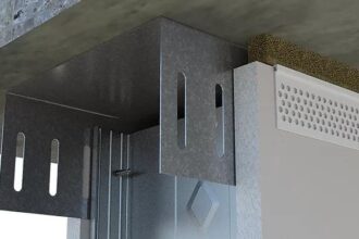
First, the receptor profile must incorporate a thermal break or be substituted with a non-metallic receptor system. Fiberglass-reinforced polymer receptor extrusions are available from several specialty fabricators and eliminate the conductivity problem entirely.
FRP extrusions in this application carry thermal conductivity values in the range of 0.25 to 0. 40 W/m·K, compared to 200 W/m·K for aluminum alloy 6063-T5. That substitution reduces the receptor Ψ-value contribution by more than 99 percent.
The structural capacity of FRP receptor profiles is adequate for typical punched window applications when the profile geometry is designed for the applied wind load and the fastener pattern is engineered for the substrate. Projects in Climate Zones 6 and 7 where receptor condensation is a documented risk should treat FRP receptor substitution as the default design decision, not an alternate.
Where aluminum receptors are retained for structural reasons, a polyamide thermal break strip bonded into the receptor profile per AAMA 505-21 methodology reduces but does not eliminate the Ψ-value contribution. A properly installed 0.25-inch polyamide strip in an aluminum receptor profile can reduce the effective Ψ-value by 60 to 75 percent depending on geometry, which may be sufficient to keep interior surface temperatures above the dew point at design conditions.
The thermal break strip approach requires that the receptor profile be designed to accommodate the strip from the outset. Field-fabricated receptors cut from stock aluminum angle cannot be thermally broken after the fact.
Second, the perimeter seal at the receptor-to-frame interface must be specified as an engineered joint, not a finishing bead. This means a minimum 3/8-inch joint width with a 3/16-inch depth (2:1 ratio per ASTM C1193-22), a closed-cell backer rod back-dam and a sealant selected for compatibility with both the receptor substrate and the window frame substrate per