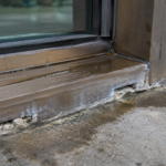
- Flashing terminated short of the soffit face and absent end dams are the two detailing failures driving bearing-point drainage in 1985-2005 commercial masonry.
- Water reaches lintel bearing points through three converging pathways: wind-driven rain infiltration, cavity condensation and capillary migration along the steel angle flange.
- Corrosion products expand up to 10 times the volume of parent steel generating pressure that fractures mortar and displaces bearing masonry laterally.
- Field assessors should document flashing terminus location end dam presence lintel coating condition and ultrasonic section loss at every bearing point.
- A pre-close inspection hold point with photographic documentation at every lintel is the single most cost-effective measure to prevent these failures in new construction.
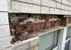
During a routine condition assessment on a 1993-vintage suburban office building, a consultant probes a staining pattern below a third-floor window opening and watches a corroded lintel bearing pad shift laterally under finger pressure. The brick soffit above had been acting as a bathtub for eleven years.
The flashing terminated two inches short of the soffit face, the end dam was absent and the weep system above had been parged over during a prior tuckpointing campaign. Nothing about the original construction was unusual.
The detailing simply reflected standard practice of the era and that is precisely the problem facing anyone assessing the 1985-to-2005 commercial masonry stock today.
The Anatomy of a Brick Soffit Condition at Steel Lintels
The soffit condition is the horizontal exposed underside of the masonry veneer as it spans across a lintel and it deserves to be treated as a distinct assembly zone rather than a footnote to the cavity wall above. It is not the vertical face of the veneer.
It is not the cavity wall. It is the plane where the veneer wraps beneath the structural steel and becomes simultaneously a water-control surface and a load-bearing interface.
Three components define this assembly: the steel angle lintel, the bearing masonry course and the through-wall flashing plane. The steel angle carries the veneer load above the opening.
The bearing masonry transfers that load to the jamb structure at each end. The flashing plane is supposed to intercept water traveling down the cavity and redirect it outward before it reaches the bearing point.
When all three components perform their intended function, the system works. When the flashing plane is absent, truncated or discontinuous, the bearing masonry becomes the water control layer by default and it is completely unqualified for that role.
Vocabulary matters in forensic documentation. Throughout this article: “bearing point” refers to the location where the lintel end bears on the masonry jamb; “soffit face” is the outward-facing edge of the horizontal veneer underside; “flashing terminus” is the leading edge of the through-wall flashing; and “end dam” is the upturned or sealed termination at the lateral edge of the flashing that prevents water from migrating sideways off the flashing plane.
BIA Technical Note 28B establishes the baseline geometry definitions for lintel and flashing conditions that forensic documentation should reference.
The bearing masonry course in a typical brick veneer soffit condition consists of one or two courses of brick laid with their bed face down against the top flange of the steel angle. Those units carry compressive load from the veneer above and transfer it horizontally to the jamb.
They are not designed to shed water. Their mortar joints are horizontal and open to the cavity above.
Their contact surface with the steel angle is a mortar bed that bonds inconsistently to mill-scale steel and degrades progressively under cyclic wetting. Treating this course as a structural element alone, without accounting for its exposure to concentrated drainage, is the fundamental design oversight that the 1985-to-2005 construction cohort reflects at scale.
NCMA TEK 19-4A addresses this assembly geometry directly and should be part of every forensic reference set for this building vintage.
How Water Actually Reaches the Bearing Point
Water reaches the lintel bearing point through three converging pathways and the bearing point sits at the low point of all three. That convergence is not coincidental.
It is a direct consequence of geometry.
The primary pathway is wind-driven rain infiltration through the veneer face. Masonry veneer is not a barrier assembly.
ASTM E514 quantifies water penetration through masonry under controlled conditions and field assemblies consistently perform worse than laboratory specimens because of mortar joint variability, unit absorption rates and construction tolerances. Water that enters the veneer face migrates inward to the cavity and then downward.
Gravity pulls it toward the lowest available horizontal surface. At a lintel, that surface is the flashing plane or in the absence of a functioning flashing plane, the top of the steel angle and the bearing masonry below it.
The second pathway is condensation within the cavity. In IECC Climate Zones 4 through 7, cavity condensation during heating season is a real and recurring moisture source.
It does not produce the dramatic intrusion volumes that wind-driven rain does, but it contributes steady background moisture loading to the bearing zone throughout the winter months. In a building with continuous air barrier deficiencies at the lintel head, warm interior air migrates into the cavity and contacts the cold steel angle directly.
The steel angle surface temperature during a heating season cold snap frequently falls below the cavity dew point and condensation forms preferentially on the steel flange. That condensate does not evaporate quickly because the bearing zone has limited ventilation and the steel provides a thermal bridge that keeps the surface cold longer than the surrounding masonry.
The result is a chronic wetting cycle at the bearing point that operates independently of any rain event.
The third pathway is capillary migration along the steel angle flange itself. The interface between the top of the steel angle and the mortar bed above it is a chronic capillary path.
Mortar does not bond reliably to mill-scale steel and the interface joint opens progressively as the steel and masonry cycle through differential thermal movement. Steel expands and contracts at approximately 6.5 millionths per degree Fahrenheit; fired clay brick runs closer to 3.
6 millionths. Over a 100-degree Fahrenheit seasonal temperature range, a 10-foot lintel accumulates roughly 0.07 inches of differential movement at each bearing end.
That gap is invisible to the eye and significant to capillary transport.
The soffit course head joints compound the problem. Head joints in the soffit course are frequently raked or left proud during construction because masons prioritize the visible face.
Those open head joints create direct capillary channels to the steel. ASTM E514 chamber setups rarely model this geometry, which creates a documentation gap when consultants attempt to correlate field observations to laboratory benchmarks.
A consultant assessing a building in this cohort should not rely on laboratory water penetration data alone to characterize the risk at the soffit bearing zone. The geometry of the soffit course, the condition of its head joints and the presence or absence of a drip edge at the soffit face are the controlling variables and they require direct field observation to evaluate.
The Flashing Termination Problem: What the Details Actually Show
Two flashing termination failures account for the majority of bearing-point drainage failures in the 1985-to-2005 construction cohort. Both are detectable in the field with basic probing.
Both were avoidable at original construction for essentially no additional cost.
The first failure is flashing terminated at the back of the brick veneer without extending to the soffit face. The installer set the flashing at the cavity face of the veneer and stopped.
Water collected on the flashing travels forward under gravity, reaches the flashing terminus and then follows surface tension back along the underside of the flashing toward the bearing point. Surface tension at a horizontal water film on a metal substrate is not a minor force at this scale.
It reliably defeats gravity across a two-to-four inch span, which is exactly the distance between a truncated flashing terminus and the bearing point.
The geometry requirement is straightforward: flashing must extend to the soffit face and turn down to create a positive drip edge. That turned-down edge breaks the surface tension path and forces water to drip free of the assembly.
Without it, the flashing functions as a water delivery system rather than a water control layer. Field observation on buildings from this era routinely shows the flashing terminus stained with mineral deposits on its underside, which is direct physical evidence that water was traveling backward along the flashing rather than dripping free at the edge.
That staining pattern, photographed and dimensioned in the assessment record, is more persuasive in a forensic context than any calculation.
The second failure is the absent or improperly formed end dam. A properly formed end dam at each jamb prevents water collected on the flashing from draining laterally off the flashing edge and into the bearing zone.
Pre-formed flashing products available during the 1985-to-2005 period frequently did not include integrated end dams. Field-formed end dams using sealant or sheet metal were inconsistently executed and almost never inspected after installation because they were concealed before the masonry closed up.
In practice, a sealant end dam applied to a dusty or damp flashing surface in cold weather has a high probability of adhesion failure within the first few freeze-thaw cycles. That failure is invisible from the exterior and produces no immediate symptom.
The symptom appears years later as bearing-zone staining and corrosion.
The code record reflects this gap directly. The 1997 UBC Section 1402.3 required flashing at lintels but provided minimal prescriptive detail on termination geometry or end dam requirements.
IBC 2021 Section 1404.4 is more specific, but the buildings in question were built and inspected under predecessor language that left termination execution entirely to field interpretation. NCMA TEK 19-4A provides the installation requirements that the code language of that era failed to specify.
Forensic assessments on pre-2000 construction should reference both the era-of-construction code and current best practice to properly frame the deviation. Documenting that the original installation met the letter of the applicable code while failing to meet the published industry standard is a distinction that matters when repair responsibility is being allocated.
The BIA and NCMA guidance was available to specifiers throughout this period. The gap was not in the published knowledge base.
It was in the translation from published guidance to project specifications and from project specifications to field execution.
Corrosion Mechanics at the Bearing Point: Why This Location Is Uniquely Aggressive
The bearing point creates a corrosion environment that is more aggressive than any other location on the lintel. Three conditions converge there simultaneously: standing water, oxygen availability at the mortar interface and chloride contamination from atmospheric deposition.
Each condition alone accelerates corrosion. Together they create an electrochemical environment that can consume significant steel section in fewer than 15 years under moderate exposure conditions.
The volumetric expansion of iron oxide is the mechanism that converts corrosion into structural damage. Steel corrosion products occupy approximately 6 to 10 times the volume of the parent steel.
That expansion generates internal pressure against the surrounding mortar and masonry units. The mortar at the bearing point is already in a compromised stress state from the bearing load above.
Add expansive corrosion pressure and the mortar fractures, the bearing masonry cracks and the lintel end begins to displace laterally. The lateral displacement observed in the opening scenario is the end state of that process.
Painted and galvanized lintels from this era frequently showed coating failure at the bearing end specifically. Field cutting of the lintel to length removed the factory coating at the cut end.
Bearing abrasion during installation removed the coating from the bottom flange. The locations with no coating were the locations with the highest water exposure.
That combination is not a coincidence of bad luck. It is a predictable outcome of detailing that ignored the coating continuity requirement at the most vulnerable location.
AISC Design Guide 3 addresses corrosion allowances in serviceability design, but masonry veneer lintel design in the 1985-to-2005 period rarely included explicit corrosion allowances for the partially embedded bearing condition. A bearing point that drains correctly may develop surface rust and remain structurally adequate for decades.
A bearing point that retains water cannot be evaluated on the same timeline. The corrosion rate in a continuously wet, partially confined steel-to-mortar interface is not the same as the corrosion rate for an exposed steel surface and the two should not be treated interchangeably in a structural adequacy assessment.
Ultrasonic thickness measurement of the lintel web and bottom flange at the bearing zone is the appropriate tool for quantifying section loss when the lintel is accessible. Readings should be taken at a minimum of three points across the bearing length and compared to the nominal section thickness from the original structural drawings or from mill certification records if available.
A section loss exceeding 25 percent of the original flange thickness at the bearing point is a threshold that warrants immediate structural review regardless of what the visual condition suggests. Corrosion at the web-to-flange junction is particularly significant because that location governs shear capacity at the bearing and section loss there does not produce visible cracking or displacement until the condition is already well advanced.
Documenting the measurement methodology, instrument calibration and reference section thickness in the assessment report is necessary to make those readings defensible in a subsequent repair specification or dispute context.
Field Identification: What to Look For During a Condition Assessment
Visual indicators of bearing-point drainage failure present in a consistent sequence that correlates roughly to the duration of the problem. Recognizing the sequence lets you estimate how long the condition has been active before you open anything up.
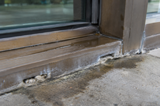
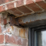
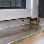
The earliest indicator is staining at the soffit course mortar joints, typically a pale mineral streak tracking outward from the bearing zone. Efflorescence follows, often tracking from the bearing point along the soffit face and down the veneer below the opening.
These two indicators can appear within two to five years of construction in a building with no functional flashing at the soffit. Efflorescence at this location is not cosmetic.
It is a tracer that identifies the drainage pathway and confirms that water is moving through the bearing zone and exiting through the soffit face or the veneer below. The mineral content of the efflorescence deposit can be sampled and analyzed if the source of the water is in dispute, though in most cases the geometry of the deposit is sufficient to establish the pathway without laboratory analysis.
Spalling or delamination of the soffit course brick face is the next stage. The freeze-thaw cycling that drives spalling is accelerated by the sustained moisture saturation at the bearing zone.
By the time face spalling is visible, the mortar at the bearing course has typically been compromised for several years. Spalling on the soffit face of the brick units directly above the bearing point, as distinct from spalling on the vertical veneer face below the opening, is a specific indicator of bearing-zone saturation rather than general veneer face exposure.
That distinction matters for prioritization because soffit-face spalling implies that the bearing masonry itself is cycling through freeze-thaw at high saturation levels, which accelerates the mortar degradation that precedes bearing displacement.
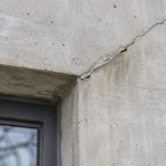
Crack patterns at the lintel ends are the most structurally significant indicator. Stepped cracks in the veneer above the lintel ends indicate differential settlement or lateral displacement of the bearing masonry.
Horizontal cracks at the bearing course itself indicate that the bearing masonry is separating from the lintel flange, often driven by corrosion expansion below. A stepped crack that originates at the lintel end and propagates diagonally upward through the veneer above the opening is a specific pattern associated with bearing point displacement and should be treated as a structural finding rather than a cosmetic one.
Crack width, orientation and any evidence of recent movement should be documented with crack monitors if the assessment scope permits ongoing monitoring.
Probing and sounding confirm what visual inspection suggests. A calibrated hammer sounding of the soffit course brick identifies hollow or debonded units before cracking is visible.
A moisture meter reading at the soffit mortar joint directly above the bearing point, taken during or immediately after a rain event, will often show readings above 20 percent by weight in a compromised assembly even when the surface appears dry. That reading, documented with instrument type, calibration date and ambient conditions, becomes the foundation of a defensible forensic record.
Readings taken more than 48 hours after a rain event may understate the moisture condition because the soffit face dries faster than the interior of the bearing zone. Scheduling moisture readings within 24 hours of a measurable rain event or using a pin-type meter with extended probes inserted into the mortar joint, produces more representative data than surface readings taken under dry conditions.
The Retrofit Problem: Why Correction Costs Are Disproportionate
The original detailing cost to extend flashing to the soffit face and form a proper end dam at each jamb was negligible. A few additional inches of flashing material, a sheet metal brake operation and a sealant termination.
Call it $15 to $30 per opening in 1993 dollars. The retrofit correction for a bearing point that has been retaining water for a decade is not in that range.
Correcting a failed soffit lintel condition requires opening the veneer above the lintel to access the flashing plane, removing and replacing the through-wall flashing with properly terminated and end-dammed material, addressing the corroded lintel (which may require sistering or full replacement depending on section loss), replacing the bearing masonry course and repointing the soffit course with appropriate mortar type. On a multi-story commercial building with dozens of openings, that scope accumulates quickly.
Scaffolding costs alone often exceed the masonry repair costs at individual openings.
Mortar type selection for the replacement bearing course deserves specific attention in the repair specification. The original mortar in a 1985-to-2005 building was frequently Type S, which is appropriate for below-grade and high-exposure applications but is stiffer than the surrounding veneer mortar and can concentrate stress at the bearing interface under thermal cycling.
ASTM C270 Type N mortar is more appropriate for the replacement bearing course in most above-grade veneer applications because its lower stiffness accommodates differential movement between the steel and the masonry without fracturing the mortar joint prematurely. Specifying the wrong mortar type in a repair that is otherwise correctly executed will reproduce the joint degradation that contributed to the original failure, typically within five to ten years.
The specification-to-field gap is the root cause. The detail existed in published guidance from BIA and NCMA throughout the 1985-to-2005 period.
The problem was not a knowledge gap at the design level. It was an inspection and verification gap at the construction level.
Flashing termination at the soffit face is not visible after the masonry closes. Without a specific pre-close inspection requirement in the project specifications, the termination condition was never verified.
Adding a mandatory pre-close inspection hold point to masonry specifications, with photographic documentation requirements for flashing termination and end dam condition at every lintel before the soffit course is laid, is the single most cost-effective quality control measure available to a specifier working on new construction or a major renovation. That hold point costs nothing to write into the specification and eliminates the primary mechanism by which these failures originate.
What the Assessment Report Needs to Document
A condition assessment that identifies soffit lintel drainage failure needs to do more than note the staining. The report needs to establish the failure mechanism, connect it to the original detailing deficiency and provide a basis for prioritizing repairs across the building.
Document the flashing terminus location using a borescope or by carefully removing a single soffit course brick at a representative bearing point. Measure and record the distance from the flashing terminus to the soffit face.
Note the presence or absence of an end dam. Record the lintel coating condition at the bearing end using the SSPC visual standards.
Measure section loss if the lintel is accessible. The borescope approach is preferable when the assessment scope does not include destructive investigation, because it allows the flashing terminus location to be documented without disturbing the bearing course.
A borescope inserted through a raked head joint in the soffit course can typically reach the flashing plane and capture sufficient image quality to measure the terminus setback and assess the end dam condition. Document the insertion point, the instrument field of view and the measurement reference in the report so that a subsequent investigator can replicate the observation at the same location.
Prioritize openings for repair based on the severity sequence described in the previous section. Openings showing only staining and efflorescence can be monitored on an 18-month cycle if resources require phasing.
Openings showing spalling, cracking or any evidence of bearing displacement require immediate investigation and likely immediate intervention. A phased repair program that addresses the most severe conditions in the first year and the moderate conditions in years two and three is a defensible approach for a building owner managing a constrained capital budget, provided that the monitoring protocol for deferred openings is specific about what conditions trigger acceleration of the repair schedule.
An 18-month monitoring cycle with no defined escalation criteria is not a plan. It is a deferral.
The assessment report should specify what observable change at a monitored opening requires the owner to move that opening into the immediate repair category before the next scheduled monitoring visit.
The buildings built between 1985 and 2005 are now 20 to 40 years old. The drainage failures that were latent at year five are active at year twenty.
The ones that were active at year ten have been generating structural displacement for a decade. Every assessment on a building in this cohort should include a systematic soffit condition survey at all lintel locations.
The cost of missing one displaced bearing pad is not recoverable.