- Brazed copper rainscreen panels on a mid-rise institutional building began showing joint separations within 18 months due to an uncalculated thermal movement budget.
- Copper’s coefficient of thermal expansion and high solar surface temperatures in dark patina conditions can double the movement demand at rigid brazed joints.
- Copper’s high galvanic potential creates predictable corrosion risk when paired with aluminum subframes or carbon steel fasteners without proper isolation.
- North American standards leave a critical gap in brazed copper panel joint engineering that European fabricators address with consolidated technical frameworks.
- Envelope engineers must require surface-temperature-based movement calculations, galvanic compatibility matrices and documented fabricator experience before copper is confirmed in any specification.
Brazed Copper Panels: Thermal and Joint Failure Risk
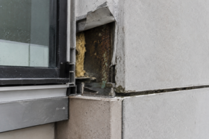
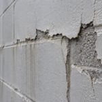
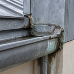
A brazed seam copper rainscreen panel system on a mid-rise institutional building in the Upper Midwest began showing hairline joint separations at panel corners within 18 months of installation, well before any warranty review cycle. The project architect attributed the failures to fabricator error.
The envelope consultant’s forensic review revealed the root cause was a thermal movement budget that was never calculated for the brazed joint geometry. The filler metal had simply been asked to absorb stress the detail was never designed to accommodate.
This scenario is not isolated and it is becoming more common as copper re-enters commercial specifications without the engineering rigor the material demands.
Why Copper Is Back on the Facade Specification Table
Copper is reappearing in commercial and institutional facade specifications at a rate not seen in North America since the mid-twentieth century. The drivers are aesthetic: architects pursuing patinated, warm-metal finishes for cultural buildings, civic centers and university projects are turning to copper as a premium alternative to zinc and weathering steel.
The sustainability narrative around recyclability adds specification cover. Copper Development Association market data shows measurable growth in architectural copper shipments post-2018, concentrated in facade cladding applications.
The problem is where the specification risk enters the project. Copper gets written into schematic design packages, often during design competition phases, before envelope engineers are engaged.
By the time the facade consultant arrives, the material is locked and the fabrication approach is assumed. European manufacturers, particularly German and Swiss firms, carry decades of brazed copper panel experience and the technical legacy to support it.
North American manufacturers are scaling up to meet demand without an equivalent knowledge base. That gap is where failures originate.
The specification pathway matters as much as the material selection itself. When copper enters a project through a design competition rendering, it arrives without a performance basis.
The architect has selected a finish, not an assembly. The difference between a copper panel system that performs for 40 years and one that begins separating at 18 months is not the copper sheet itself.
ASTM B152 copper sheet is a consistent, well-characterized material. The difference is the joint engineering, the thermal movement budget and the galvanic isolation strategy, none of which exist in a competition rendering.
Owners and project managers who accept copper as a confirmed material before those three items are resolved are accepting a risk they cannot see in the specification document.
What Brazed Seam Construction Is and How It Differs from Mechanical Joinery
Brazing in copper panel fabrication means joining metal using a filler material, typically a phosphor-copper alloy (BCuP series) or a silver-alloy filler, applied at temperatures between 840°F and 1,650°F (450°C to 900°C). That temperature range sits below copper’s melting point of approximately 1,984°F (1,085°C), which is what distinguishes brazing from welding.
It also sits well above soldering temperatures, which top out around 840°F. Per AWS C3.4 (Specification for Torch Brazing), the process requires controlled heat application and flux management to achieve a sound metallurgical bond.
In a shop fabrication context, that means operator skill and process discipline are load-bearing variables.
The brazed seam geometry in facade panels typically involves folded seam edges bonded with filler to create a rigid, continuous joint. This is the core engineering problem.
A mechanically seamed or clipped floating panel system accommodates differential thermal movement through slip at clip connections and rotation at seam edges. The brazed joint does neither.
It transfers thermal stress directly into the bond line. Common configurations where brazing gets specified include box-pan corners, cassette panel returns and reveal edge closures.
These are exactly the panel geometries where corner stress concentrations are highest and where thermal movement vectors from two perpendicular panel faces converge at a single joint. Per AWS A2.4 terminology, the brazed joint in these configurations functions as a rigid connection, not a flexible one.
Treating it otherwise in the design phase is the first error.
The operator skill variable deserves more attention than it typically receives in specification documents. AWS C3.4 establishes process requirements, but it does not certify individual operators for architectural facade work.
A fabricator producing HVAC components under the same brazing standard is operating in a fundamentally different service environment than one producing exterior facade panels subject to cyclic thermal loading over decades. The joint quality in a brazed copper panel is a direct function of heat control consistency, flux residue removal and filler flow uniformity across the full seam length.
Pinholes, cold joints and incomplete filler penetration are not always visible in shop inspection. They become visible when cyclic thermal stress opens the bond line from the inside out, typically at corners where stress concentration is highest.
Thermal Movement Mechanics in Copper: The Numbers That Matter
Copper’s coefficient of thermal expansion is 9.8 x 10 to the negative sixth power inches per inch per degree Fahrenheit (17. 6 x 10 to the negative sixth power meters per meter per degree Celsius).
For a 1,200mm panel across a 56°C (100°F) service temperature delta, that calculates to approximately 1.18mm of free thermal movement. That number sounds manageable.
It is not, when the joint accommodating it has zero designed slip capacity.
Dark patinated copper in full solar exposure is a separate problem. ASTM E1918 solar reflectance testing methodology establishes the framework for evaluating surface temperatures under solar load.
Dark oxidized copper surfaces in summer conditions in IECC Climate Zones 4 through 6 routinely reach 160°F to 180°F (71°C to 82°C). If the design temperature delta was calculated using ambient air temperature range rather than surface temperature range, the actual service delta may be 40°F to 60°F higher than assumed.
That error alone can double the calculated movement demand at the joint.
Thermal fatigue compounds the problem over time. A single overstress event at installation might not produce visible failure.
Cyclic daily thermal movement over five to ten years accumulates plastic strain at the bond line through low-cycle fatigue. The brazed joint does not recover between cycles.
CDA Publication 110 (Copper in Architecture) includes thermal expansion tables that establish the baseline movement calculations; what it does not address is the fatigue accumulation in rigid joint configurations. ASTM E2112 governs movement accommodation in exterior assemblies but applies to fenestration installation practice, not opaque panel systems.
The movement budget for a brazed copper rainscreen panel system falls into a standards gap and envelope engineers need to close that gap themselves in the design phase.
The panel size variable is frequently underweighted in early design decisions. Architects specifying large-format copper panels for visual effect, panels in the 1,500mm to 1,800mm range, are compounding the thermal movement problem proportionally.
A 1,500mm panel at the same 56°C delta produces approximately 1.48mm of free movement. That additional 0.3mm relative to the 1,200mm panel may appear trivial in isolation, but it represents a 25 percent increase in stress demand at the corner joint.
When the joint has no designed slip capacity, that increase is not absorbed gradually. It accumulates as plastic strain at the bond line with each thermal cycle.
Envelope engineers reviewing large-format copper panel specifications should apply a size penalty factor to the fatigue life assessment and document the basis for the assumed joint capacity explicitly in the project record.
Galvanic Incompatibility in the Substrate and Fastener Stack
Copper sits high on the galvanic series, with a standard electrode potential of approximately +0.34V. Place it in contact with aluminum subframing, carbon steel fasteners or zinc-coated components in the presence of moisture and you have a functioning galvanic cell.
The less noble material corrodes preferentially. This is not a theoretical risk; it is a predictable electrochemical outcome that North American installation guides routinely underdetail.
The most common incompatibility scenario in brazed copper rainscreen assemblies involves aluminum extrusion subframes. Aluminum is approximately 1.4V to 1.
6V removed from copper on the galvanic series per MIL-STD-889 reference tables. In a cavity rainscreen assembly where condensation and wind-driven moisture are present by design, that separation guarantees accelerated aluminum corrosion at contact points.
Hot-dip galvanized fasteners at panel anchors present a similar problem. Stainless steel fasteners (Type 304 minimum, Type 316 in coastal exposures) are the correct specification.
The brazed joint itself introduces a third variable. BCuP brazing filler alloys have a different electrochemical profile than the parent copper sheet.
Per ASTM G82 (galvanic corrosion testing methodology), dissimilar alloy contact in an electrolytic environment creates a preferential corrosion site at the filler-to-parent-metal interface. If the filler alloy selection was not reviewed against the full substrate stack, the joint becomes the weakest link in the corrosion hierarchy, not just the weakest link in the thermal movement hierarchy.
EPDM or neoprene isolators and non-conductive washers at dissimilar metal interfaces are required practice, not optional detailing. Most North American manufacturer installation guides do not specify isolator thickness, durometer or continuity requirements at the level the assembly actually demands.
The coastal exposure condition warrants specific attention beyond fastener material selection. In ASCE 7 wind-driven rain exposure categories and within the corrosion zones defined by ASTM B117 salt spray testing protocols, the electrolytic environment at dissimilar metal interfaces is significantly more aggressive than in inland installations.
A copper panel system installed within two miles of a saltwater coastline should be treated as a marine exposure for galvanic isolation purposes regardless of what the project’s geographic classification suggests. That means Type 316L stainless fasteners, continuous EPDM isolators with a minimum 3mm thickness and 60 durometer hardness and a documented inspection interval in the owner’s maintenance plan.
These requirements should appear in Division 07 specifications as mandatory items, not as notes on a detail sheet that may or may not survive the construction documents coordination process.
Where North American Detailing Standards Fall Short
The European practice gap in brazed copper facade detailing is real and consequential. German and Swiss fabricators working under DIN EN 1172 (copper and copper alloy strip and sheet for building purposes) and referencing ZVDH technical guidelines for metal roofing and cladding carry joint movement calculations, thermal fatigue protocols and galvanic isolation requirements as standard deliverables.
North American practice does not have an equivalent consolidated technical framework for brazed copper panel systems.
SMACNA’s Architectural Sheet Metal Manual addresses copper in roof and wall flashing applications but does not cover brazed cassette panel fabrication at the joint engineering level. The Copper Development Association’s guidance documents are useful reference materials but are not performance specifications.
ASTM B152 (copper sheet and strip) governs material properties; it says nothing about joint design for thermal cycling service. This leaves envelope engineers in a position where they must assemble a performance framework from multiple partial sources, none of which were written for this specific application.
The practical consequence is that brazed copper panel specifications in North America frequently arrive at the construction documents phase without a joint movement calculation, without a galvanic isolation schedule and without a thermal fatigue life assessment. The fabricator fills the gap with shop practice.
Shop practice is not engineering. When the joint separates at 18 months, the forensic trail leads back to a design phase decision that was never made.
The standards gap also creates a procurement problem. When an owner’s representative or construction manager reviews a brazed copper panel submittal, there is no North American reference standard against which to evaluate the fabricator’s joint design documentation.
A submittal that includes a thermal movement calculation and a galvanic isolation matrix looks thorough by comparison to one that does not, but neither the construction manager nor the architect’s project manager typically has the technical basis to evaluate whether the calculation methodology is correct or whether the assumed joint capacity is realistic. The envelope engineer of record needs to establish explicit submittal acceptance criteria in the specification, including the calculation methodology, the temperature assumption basis and the minimum required documentation for fabricator qualification.
Without those criteria in the specification, the submittal review process cannot function as a quality gate.
The Specification-to-Field Gap at Panel Corners and Returns
Panel corners and returns are where brazed seam failures concentrate and the geometry explains why. At a box-pan corner, thermal movement from the face panel and thermal movement from the return panel are perpendicular vectors.
The brazed joint at the corner must resist the resultant of both. In a floating mechanical system, that corner is a hinge point.
In a brazed assembly, it is a stress concentration with no designed relief.
Field installation compounds the problem. Brazed panels arrive on site as finished assemblies.
The envelope contractor installs them into a subframe system that may have been detailed by a different party than the panel fabricator. If the clip spacing and anchor point locations were not coordinated against the panel’s thermal movement budget, the panel is constrained at intervals that force the joint to absorb movement the anchor system should be accommodating.
This is a coordination failure that standard submittal review processes do not reliably catch, because the reviewer is looking at the panel drawing and the subframe drawing separately, not at their combined thermal behavior.
The anchor point location problem is particularly acute at building corners, where the subframe transitions from one facade plane to another. A panel installed at a building corner is subject to thermal movement vectors from two building faces simultaneously, compounding the stress concentration that already exists at the panel’s own brazed corner joint.
Envelope contractors who have not worked with brazed copper panels before will default to anchor spacing that matches their experience with aluminum composite or fiber cement panel systems. Those systems have fundamentally different thermal movement characteristics and joint flexibility.
The subframe detailing that works for an aluminum composite panel system will over-constrain a brazed copper panel and accelerate joint fatigue. Require the fabricator and the subframe supplier to produce a coordinated anchor point layout drawing that documents the thermal movement accommodation strategy as a single integrated deliverable, not as two separate submittals reviewed independently.
Require a joint movement calculation as a fabricator submittal. Require it to address surface temperature delta, not ambient temperature delta.
Require the galvanic isolation schedule as a separate deliverable. These are not extraordinary requests.
They are the minimum engineering basis for a brazed copper facade system.
What Envelope Engineers Should Require Before Copper Gets Specified
The forensic pattern across brazed copper panel failures points to a consistent set of missing deliverables at the design and procurement phase. Before copper is confirmed in a specification, the envelope engineer needs four things on the table: a thermal movement calculation using ASTM E1918-calibrated surface temperature assumptions, a joint design that explicitly addresses movement accommodation or documents the fatigue life basis for a rigid joint, a galvanic compatibility matrix for every material in the substrate stack from panel face to structural backup and a fabricator qualification record that includes documented experience with brazed copper in ventilated rainscreen configurations specifically.
That last requirement will eliminate a significant portion of the North American market. That is the point.
Copper is a demanding material in brazed seam facade applications and the consequences of underengineering it show up in the envelope within two years. The aesthetic case for copper is strong.
The engineering case for specifying it without a rigorous joint performance basis is not. Architects and owners who want copper on a building need an envelope engineer in the room at schematic design, not at construction documents.
By the time the specification is written, the decisions that determine whether the joints survive have already been made.
The fabricator qualification requirement deserves a defined minimum threshold in the specification language itself. A general requirement for “demonstrated experience” is not enforceable.
Specify a minimum number of completed brazed copper rainscreen projects by panel count or installed area, require photographic documentation of installed work at a minimum of two reference projects and require contact information for the envelope consultant or architect of record on each reference project. Require the fabricator to submit the thermal movement calculation methodology used on a prior project as a demonstration of technical capability, not just a list of project names.
These qualification criteria will not guarantee a successful outcome, but they establish a documented basis for fabricator selection that protects the owner and the design team when performance questions arise later. The 18-month failure scenario described at the outset of this article is recoverable with forensic investigation and remediation.
The reputational and contractual consequences of that failure are not.