- UL 1479 listings are substrate-specific and most are tested in gypsum or concrete, not aluminum composite panels or rainscreen assemblies.
- NFPA 285 evaluates wall assemblies as a system and does not assess individual penetration seals for weathering or thermal cycling performance.
- UV exposure, freeze-thaw cycling and thermal movement degrade intumescent sealant adhesion before any fire event occurs.
- MEP and facade engineers routinely fail to coordinate exterior penetration firestopping, leaving no one accountable for substrate or movement verification.
- A defensible specification requires substrate-matched listings, documented annular space dimensions, primer requirements and facade engineer review before installation.
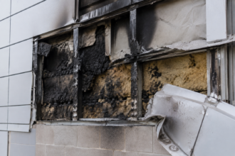
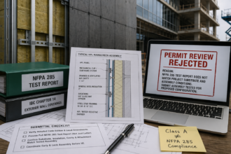
During a pre-occupancy firestopping inspection on a mid-rise mixed-use project in a coastal climate, an AHJ rejected intumescent sealant installations at a series of exterior wall penetrations. Not because the product lacked a listing.
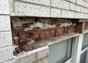
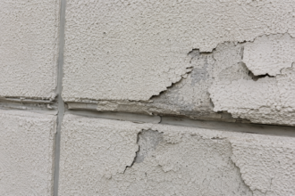
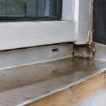
Because the sealant had visibly debonded from an aluminum cladding substrate after less than 18 months of exposure. The product had been specified from a UL-listed assembly detail, but no one had verified whether that listing addressed exterior weathering conditions or joint cycling.
The rejection triggered a full re-inspection of the exterior penetration schedule, a three-week schedule delay and a design liability dispute between the envelope consultant and the MEP engineer of record. That scenario is not unusual.
It is becoming more common as AHJs increase scrutiny of exterior firestopping under NFPA 285 compliance reviews.
Exterior Wall Penetrations Are Not Interior Firestopping: And the Code Doesn’t Always Acknowledge the Difference
IBC Chapter 7 firestopping requirements were developed primarily around interior fire-rated assemblies. The framework in IBC Section 714 addresses through-penetration firestop systems with reasonable specificity for gypsum and concrete assemblies in conditioned, stable environments.
Exterior wall penetrations operate under an entirely different set of physical conditions and the code does not fully account for that distinction.
NFPA 285 evaluates the exterior wall assembly as a system for vertical flame propagation. Its scope addresses the wall system, not the individual penetration seals within it.
That gap matters. A wall assembly can achieve NFPA 285 compliance as tested while containing penetration seals that have no evaluated performance under weathering, UV exposure or thermal cycling.
Facade engineers are routinely handed penetration firestopping specifications developed by MEP teams that treat exterior penetrations as interior conditions with a weather barrier added. That assumption fails in practice.
Exterior penetrations at the cladding plane are exposed to UV degradation, moisture infiltration, freeze-thaw cycling and continuous joint movement from thermal expansion of the cladding substrate. None of those conditions appear in the standard UL 1479 test protocol.
The specification-to-field gap starts here, at the point where two engineering disciplines hand off responsibility without reconciling the performance requirements each discipline is working from. A concrete example: a mechanical contractor installing a 4-inch conduit sleeve through an aluminum composite panel rainscreen system in Climate Zone 6 is working from a firestopping specification that was written against a UL-listed assembly tested in 5/8-inch Type X gypsum wallboard at a controlled 70 degrees Fahrenheit.
The substrate is different, the exposure is different and the joint movement profile is different. The specification writer either did not check or assumed the listing was transferable.
Neither assumption holds under IBC Section 714.4.1, which requires installation as tested. AHJs in jurisdictions with active NFPA 285 enforcement programs are beginning to ask for substrate verification documentation at the penetration level, not just wall assembly test reports.
Projects that cannot produce that documentation are being flagged for remediation and the cost of remediation at an occupied or nearly occupied building is orders of magnitude higher than the cost of getting the specification right at the construction document stage.
Understanding the Listing: What UL and FM Approvals for Intumescent Sealants Actually Cover
UL 1479 (which corresponds to ASTM E814) is the test method for through-penetration firestop systems. Listings issued under this standard are assembly-specific and substrate-specific.
That specificity is the point. A listing is not a general approval of a product; it is an approval of a tested configuration.
The problem is that most UL-listed intumescent sealant assemblies are tested in gypsum wallboard, poured concrete or concrete masonry unit substrates. Aluminum composite panels, fiber cement board, open-joint rainscreen substrates and EIFS base coats are not the tested conditions in the majority of published listings.
Specifiers who pull a listed assembly detail and apply it to an ACM-clad exterior wall without verifying substrate match are not working within the listing. They are working outside it.
IBC Section 714.4.1 requires that through-penetration firestop systems be installed as tested. That language is unambiguous.
The UL Product iQ database provides the tested substrate, annular space geometry and penetrant type for each listed assembly. Verifying that the project condition matches the listing is not optional.
It is a code compliance requirement.
FM Approvals operates a parallel listing program under FM 4991, which evaluates firestop systems under the FM loss prevention framework. FM-listed assemblies appear in the FM Approval Guide and carry their own substrate and configuration restrictions.
On projects with FM Global property insurance requirements, the specifier may be obligated to use FM-listed systems rather than or in addition to UL-listed systems. The two databases do not always contain identical listings for the same product and a system listed under UL 1479 is not automatically FM-approved.
Specifiers on FM-insured projects who default to UL Product iQ without checking the FM Approval Guide are creating a compliance gap that the owner’s insurer may identify during a post-construction loss prevention survey.
Listings also do not include weathering durability, UV resistance or joint movement cycling as pass/fail criteria. A product can carry a UL listing and still be entirely inappropriate for an exterior exposure condition.
The listing tells you the product performed in a fire test under laboratory conditions. It tells you nothing about whether that performance will be retained after two winters in IECC Climate Zone 6. Manufacturer technical data sheets occasionally include supplemental weathering test data, but that data is not part of the listing and carries no third-party verification.
Specifiers who rely on TDS weathering claims without requesting the underlying test reports are accepting unverified performance representations as the basis for a life-safety specification.
UV Exposure, Moisture Cycling and Freeze-Thaw: How the Exterior Environment Attacks Intumescent Sealant Before Any Fire Occurs
Intumescent sealants rely on graphite or sodium silicate chemistry to generate the volumetric expansion that seals a penetration under fire conditions. Both chemistries are vulnerable to prolonged UV exposure.
Surface hardening from UV degradation reduces the sealant’s ability to expand uniformly under heat and it accelerates adhesion loss at the substrate interface. A sealant that has surface-hardened after two or three years of southern exposure may still look intact visually while having lost a significant portion of its functional expansion ratio.
Moisture infiltration compounds the problem. In cavity wall and rainscreen assemblies, the penetration often occurs at the back of a drained cavity where the sealant is exposed to water that has entered the cavity intentionally as part of the drainage design.
That moisture, cycling through freeze-thaw conditions in IECC Climate Zones 5 through 7, works into the sealant body and the substrate interface. Adhesion loss follows.
Published expansion ratio data for intumescent sealants typically ranges from 3:1 to 10:1 depending on product formulation. That data is measured at installation under controlled conditions.
No standardized field verification method exists to confirm retained expansion capacity after weathering. You cannot core-test an installed intumescent sealant the way you can test installed concrete.
The performance degradation is invisible until the assembly is destructively examined or a fire event reveals it.
Graphite-based intumescent formulations generally show greater UV resistance than sodium silicate formulations, but neither chemistry has been evaluated under a standardized accelerated weathering protocol that also measures retained fire performance. ASTM G154 and ASTM G155 are the standard accelerated weathering test methods for UV exposure, but neither is cross-referenced to intumescent expansion performance.
A manufacturer running its own weathering program may use one of those methods to generate UV exposure data and report color change or surface hardness results without ever measuring whether the expansion ratio changed. That selective reporting is not fraudulent, but it is not the information a specifier needs to make a defensible exterior firestopping decision.
ASTM C920 addresses weathering performance for sealants, covering adhesion and cohesion under cycling conditions. It does not cross-reference intumescent performance retention.
The two performance regimes are tested independently and never jointly. That is a gap in the standard framework that the industry has not resolved.
Until a combined protocol exists, specifiers working on exterior applications in high-UV or severe freeze-thaw environments should require manufacturers to provide third-party weathering test data and should document in the project record that no combined standard currently exists. That documentation step does not solve the technical problem, but it establishes that the specifier understood the limitation and made a reasoned product selection rather than defaulting to an interior-condition listing.
Thermal Movement, Substrate Incompatibility and the Mechanical Failure Modes Specifiers Overlook
Exterior cladding systems undergo thermal movement that dwarfs what interior assemblies experience. An aluminum composite panel system in a high-solar-gain orientation can cycle through 100 degrees Fahrenheit of temperature differential in a single day.
That movement translates directly to the penetration joint. Intumescent sealants have limited elongation capacity, typically in the range of 15 to 25 percent depending on formulation.
Silicone sealants rated for dynamic joints routinely achieve 50 percent or greater. Specifying an intumescent sealant at a moving exterior joint without a backer rod, a joint design review and explicit confirmation that the elongation capacity matches the anticipated movement range is a specification error.
It is not a gray area.
The calculation is not difficult. AAMA 501.4 provides guidance on cladding movement benchmarks and the coefficient of thermal expansion for aluminum is approximately 13 x 10 to the negative 6 power per degree Fahrenheit.
A 10-foot panel span cycling through 100 degrees Fahrenheit generates approximately 0.156 inches of linear movement. If the penetration joint width is 3/4 inch, that movement represents a 20 percent change in joint width, which is at or beyond the elongation limit of most intumescent sealant formulations.
A specifier who has not run that calculation or who has not asked the facade engineer to run it, has not verified that the specified product can accommodate the actual field condition.
Substrate incompatibility is the second mechanical failure mode. Many intumescent sealants are not chemically compatible with aluminum oxide surfaces, powder-coated finishes or EIFS base coats without a primer.
Primer application is a step that field crews skip with regularity, particularly when the penetration is located in an awkward geometry behind a cladding panel or within a cavity that requires disassembly to access. The manufacturer technical data sheet specifies primer requirements.
Those requirements need to appear in the project specification with the same clarity as the product designation itself.
Field observations from exterior wall commissioning programs consistently show primer omission as one of the most common installation deficiencies at exterior penetrations. On one documented rainscreen project in the Pacific Northwest, roughly 40 percent of exterior penetration seals installed without primer showed measurable adhesion loss within 24 months.
The installer had read the product designation in the specification but the primer requirement appeared only in the manufacturer’s TDS, which was not referenced in the project documents. That is a specification writing failure, not an installer failure.
The annular space geometry at exterior penetrations is frequently larger and more irregular than interior conditions. UL 1479 listings specify the tested annular space range.
If the field condition exceeds that range, the listing is voided. AAMA 501.4 provides context for cladding movement benchmarks, but the penetration seal designer needs to work from the actual calculated movement at the penetration location, not a generic reference value.
Sleeve sizing at exterior penetrations is often driven by the MEP contractor’s sleeve schedule, which is optimized for pipe clearance and installation speed rather than firestopping compliance. When the sleeve diameter is set before the firestopping specification is written, the annular space may already be outside the tested range before a product has been selected.
Coordinating sleeve sizing with firestopping listing requirements is a pre-design coordination step that most project teams do not take.
NFPA 285 Compliance at Penetrations: What AHJs Are Asking For and Why the Answers Are Inconsistent
NFPA 285 evaluates vertical flame propagation through exterior wall assemblies. The test protocol evaluates the wall system as a whole.
It does not test individual penetration seals within that assembly and it does not evaluate the wall assembly under weathering conditions. That scope limitation creates a compliance interpretation problem that plays out differently in every jurisdiction.
Some AHJs accept a UL 1479-listed penetration firestop system as satisfying the NFPA 285 compliance requirement at the exterior wall plane, reasoning that the penetration seal is a separate code compliance element addressed under IBC Section 714 rather than the wall assembly compliance addressed under NFPA 285. Other AHJs take the position that any penetration through an NFPA 285-compliant assembly must itself be evaluated within the context of that assembly and a standalone UL 1479 listing is insufficient without documentation that the penetration seal was part of the tested assembly or is evaluated in a specific engineering judgment.
That interpretive split is not hypothetical. Projects in jurisdictions with active high-rise enforcement programs, including several major metropolitan building departments that adopted the 2021 IBC with local amendments, have seen pre-occupancy inspections stall specifically on this question.
The AHJ’s position is sometimes not documented in any published policy or local amendment. It exists as institutional practice within the plan review staff and it surfaces for the first time during inspection.
By that point, the penetrations are installed, the cladding is in place and remediation requires partial cladding removal.
Engineering judgments (EJs) are the industry’s primary tool for bridging the gap between listed assembly conditions and project-specific conditions. A qualified EJ from a firestop specialty engineer can address substrate variations, annular space deviations and penetrant type differences.
What EJs cannot do is address weathering durability. An EJ evaluates fire performance under the same laboratory-condition assumptions as the underlying test.
It does not evaluate whether the installed assembly will retain that performance after three years of exterior exposure.
The International Firestop Council publishes guidance on engineering judgment preparation and the FM Global Property Loss Prevention Data Sheet 1-57 addresses firestop system equivalency evaluations. Neither document establishes a weathering durability evaluation framework for exterior applications.
Specifiers who obtain an EJ for a non-standard exterior penetration condition have addressed the fire performance gap but have not addressed the durability gap. Both gaps need to be documented and both need to be disclosed to the AHJ.
The inconsistency in AHJ interpretation is real and it creates project-level liability. Specifiers need to confirm the local AHJ’s position on NFPA 285 penetration compliance before construction documents are issued, not during the pre-occupancy inspection.
The Specification Gap: Where MEP and Envelope Coordination Breaks Down
The liability dispute in the scenario at the top of this article was predictable from the project’s coordination structure. The MEP engineer of record specified the firestopping system based on interior performance criteria.
The envelope consultant reviewed the exterior wall assembly for NFPA 285 compliance but did not review the penetration firestopping specification for weathering appropriateness. Neither party explicitly owned the intersection.
This coordination gap is structural. Firestopping specifications typically live in Division 07 84 00, which is often written by the MEP team or a firestopping specialty consultant without input from the facade engineer.
The facade engineer, who understands the thermal movement, substrate conditions and drainage cavity geometry at the penetration, is not in the review chain for the firestopping spec. That needs to change.
The problem is reinforced by how design contracts are typically scoped. The facade engineer’s scope of work is defined around the wall assembly, the cladding system and the air and water barrier.
Penetration firestopping is treated as a mechanical or fire protection scope item. The result is that the person with the most relevant knowledge of the exterior substrate conditions, joint movement profiles and cavity drainage geometry has no contractual obligation to review the firestopping specification and no standard workflow that puts that specification in front of them.
On design-build projects, the problem is sometimes worse because the firestopping specification may be written by the installing subcontractor based on product availability rather than by a design professional at all.
Best practice requires the facade engineer to review the penetration firestopping specification for every exterior wall penetration and confirm four things: that the listed assembly substrate matches the actual cladding substrate, that the tested annular space range covers the field condition, that the elongation capacity of the sealant accommodates the calculated thermal movement at the penetration location and that the product’s weathering performance has been evaluated for the project’s climate zone and exposure category. None of those four checks are optional if the goal is a compliant installation that retains its performance over the service life of the building.
Project specifications should explicitly assign the exterior penetration firestopping coordination responsibility to a named party. The Division 07 84 00 specification section should include a coordination requirement that directs the firestopping installer to submit penetration locations and substrate conditions to the facade engineer of record for review before installation begins.
That review step adds minimal time to the schedule and creates a documented record that the substrate match was verified. Without that record, the liability question after a failed inspection defaults to whoever signed the specification, which is typically the MEP engineer of record working from interior-condition assumptions.
What a Defensible Exterior Penetration Firestopping Specification Actually Requires
The path forward is not complicated, but it requires discipline at the specification stage that the industry is not consistently applying. Start with the substrate.
Confirm the exact cladding material, finish and surface condition at the penetration location. Pull the UL Product iQ listings for intumescent sealants and filter for substrate match.
If no listing covers the actual substrate, the options are an engineering judgment from a qualified firestop engineer or a different product category.
For penetrations in drained or vented cavity wall assemblies, specify a sealant that has documented weathering test data, even if that data comes from ASTM C920 testing rather than a combined fire-plus-weathering protocol. Require primer application in the specification and make it an inspectable item in the special inspection program under IBC Section 1705. The special inspection requirement for firestopping under IBC Section 1705.
16 applies to fire-rated assemblies and the inspection program should be written to include exterior penetrations explicitly. Generic special inspection programs that address firestopping as a single line item without distinguishing interior from exterior conditions are not adequate for projects with significant exterior penetration schedules.
Require the installing contractor to document annular space dimensions at each exterior penetration location before sealant installation. If the field condition exceeds the tested range, stop and resolve it.
That documentation step costs almost nothing and creates the record that protects all parties if the installation is later challenged. A simple field log with penetration location, sleeve diameter, pipe or conduit diameter, calculated annular space and listing reference number takes less than five minutes per penetration to complete.
On a project with 200 exterior penetrations, that is roughly 16 hours of documentation labor against a potential remediation cost that can reach six figures if debonded or out-of-range installations are discovered during pre-occupancy inspection.
Submittal requirements in the specification should go beyond the standard product data sheet and installation instructions. Require the contractor to submit a penetration firestopping schedule that maps each exterior penetration to its specific UL or FM listing, identifies the tested substrate and annular space range for that listing and confirms that the field condition falls within the tested parameters.
That schedule becomes a project record and a verification tool for the special inspector. If the contractor cannot produce that schedule, the specification has not been followed and the installation should not proceed.
The deeper problem is that the industry needs a combined test protocol that evaluates intumescent sealant performance after accelerated weathering exposure, not just under laboratory fire conditions. Until that standard exists, every exterior intumescent sealant installation carries an unquantified performance risk.
ASTM Committee E06 on Performance of Buildings and the International Firestop Council are the appropriate bodies to develop that protocol and the technical framework for combining accelerated weathering exposure with post-exposure fire testing already exists in adjacent standards. The gap is not a technical barrier; it is a prioritization gap within the standards development process.
Specifiers who understand that risk and document their design decisions accordingly are in a defensible position. Those who specify by habit from interior firestopping details are not.