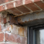
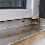
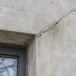
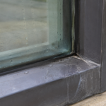
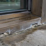
- Forensic investigation of a mid-Atlantic building found water intrusion at 34 of 48 window openings traced to improperly fabricated aluminum sill pans.
- Specifications that say only slope to drain without prescribing minimum values allow fabricators to form flat pans that pond water and fail.
- End dam heights below 1.5 inches and pop-riveted corner joints are consistently underbuilt details that fail under real storm conditions.
- Weep holes drilled at installer discretion are routinely placed too high above the pan floor to drain water before it finds a failure path.
- Passing an AAMA 501.2 mockup test does not validate sill pan geometry and cannot substitute for prescriptive dimensional requirements in contract documents.
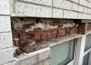
A forensic investigation of a four-story mixed-use building in the mid-Atlantic region revealed water intrusion at 34 of 48 punched window openings. Every failure traced back to field-fabricated aluminum sill pans with flat bottoms, undersized end dams and weep holes drilled by the glazing subcontractor without reference to any engineered detail.
The building had passed a pre-installation mockup test per AAMA 501.2, yet water was migrating into stud cavities within the first rainy season. That disconnect between a passing test and a failing assembly is the problem this article addresses directly.
Why the Sill Pan Is the Assembly’s Most Consequential Component
The sill pan is not the first line of defense at a window opening. It is the last.
By the time water reaches the pan, the window unit has allowed infiltration, the sealant joint has partially failed and the flashing integration has performed imperfectly. All three of those conditions occur routinely in commercial construction, regardless of specification quality.
The pan is what stands between that water and the stud cavity.
Water intrusion at window-to-wall interfaces consistently ranks as the leading cause of commercial construction litigation. NIBS forensic survey data and insurance industry reporting both point to fenestration perimeter conditions as the primary failure zone in commercial assemblies.
The sill condition accounts for the largest share of those failures because water accumulates there by gravity.
Field-fabricated brake-metal pans dominate commercial punched and storefront openings precisely because they accommodate variable rough opening dimensions and substrate conditions. That adaptability is legitimate.
The failure mechanism is not the material; it is the absence of constraint on geometry. When a specification says “form aluminum sill pan” without prescribing slope, end dam height or weep placement, the installer fills that vacuum with shop habit.
AAMA 2410-15 makes clear that sealant alone at sill conditions cannot be relied upon as the primary water control layer. Geometry must do the work.
The thesis here is simple: slope, end dam height and weep placement must be prescribed in the contract documents, not assumed.
How Brake-Metal Sill Pans Are Currently Specified: and Where the Detail Stops
Open a typical project manual for a commercial office building and find the fenestration section. The sill pan language will read something like: “Provide formed aluminum sill pan flashing at all window and door openings; slope to drain.
” That is the entire geometric prescription. No minimum slope.
No end dam height. No weep hole diameter or spacing.
No requirement that slope be built into the brake-formed geometry rather than shimmed in the field.
The shop drawing review process does not catch this. Reviewers are checking material compliance: alloy designation, gauge, finish.
They are not checking pan geometry because the contract documents never established a geometric baseline to check against. A shop drawing that shows a flat-bottom pan with 3/4-inch end dams sails through review because nothing in the specification says it is wrong.
The reviewer stamps it “reviewed” or “reviewed as noted,” and that approval becomes the fabrication instruction. The flat pan gets built.
The flat pan gets installed. The flat pan fails.
The responsibility gap compounds the problem. The architect delegates pan geometry to the glazing contractor.
The glazing contractor delegates fabrication to the sheet metal installer. The sheet metal installer defaults to whatever the shop has been forming for the last decade.
The result is three different pan profiles on the same project, none of them engineered and none of them reviewed against a performance requirement. On one mid-Atlantic office project reviewed by this author, four separate sheet metal subcontractors produced pans on the same building with end dam heights ranging from 5/8 inch to 1-3/8 inches and back leg heights ranging from 1 inch to 2-1/2 inches.
Every pan passed shop drawing review. None of them matched a prescriptive detail because no prescriptive detail existed.
IBC 2021 Section 1404.4 establishes that flashing is required at window and door openings but provides no geometry prescription whatsoever. ASTM E2112-19 (Standard Practice for Installation of Exterior Windows, Doors and Skylights) is the closest available guidance document and it goes further than code, but its recommendations are still not mandatory unless the specification invokes them explicitly and requires compliance rather than reference.
The distinction between “reference” and “compliance requirement” in a specification is not semantic. A reference document informs the contractor.
A compliance requirement binds the contractor. Most specifications reference ASTM E2112-19. Almost none require compliance with its geometric recommendations.
That gap is where the failures live.
The division of responsibility between CSI MasterFormat sections creates an additional coordination problem. Section 07 62 00 (Sheet Metal Flashing and Trim) and Section 08 51 13 (Aluminum Windows) frequently contain conflicting or incomplete pan requirements because the two sections are written by different specifiers or assembled from different master guide specifications without cross-referencing.
The glazing contractor reads Section 08 51 13. The sheet metal contractor reads Section 07 62 00. Neither section contains a complete geometric prescription and neither contractor reads the other’s section.
The pan geometry falls into the gap between them.
End Dam Geometry: The Most Consistently Underbuilt Detail
End dams fail more often than any other sill pan component. The reason is not complicated: the joint between the end dam and the pan floor is the primary leak path in a field-fabricated assembly and that joint is almost always executed incorrectly.
The minimum 1-inch end dam height cited in common practice is not derived from hydraulic analysis. It is a convention.
For a commercial opening 48 inches wide in a mid-Atlantic climate with design rainfall intensities exceeding 8 inches per hour during storm events, 1 inch of end dam containment is inadequate. A prescriptive baseline of 1.5 inches minimum for openings wider than 36 inches is defensible and should be written into the specification as a floor, not a target.
For wider openings or higher-exposure conditions, a project-specific hydraulic calculation is warranted. The calculation is not complicated: estimate the water volume entering the pan under design conditions, account for drainage capacity at the weep locations and confirm that the end dam height exceeds the maximum water depth that will accumulate before the weeps can evacuate it.
That calculation takes less time than a single remediation site visit.
End dam height is only part of the problem. The joint between the end dam fold and the back leg of the pan must be continuous and properly sealed.
Field-fabricated pans frequently use a pop-riveted lap at this corner rather than a brake-formed monolithic return. A mechanically fastened lap joint relies entirely on sealant continuity at an inside corner that is difficult to tool, subject to adhesion failure against mill-finish aluminum without primer and exposed to differential thermal movement between the pan and the window frame.
Aluminum expands at approximately 0.0000131 inches per inch per degree Fahrenheit. A 48-inch-wide pan subjected to a 100-degree Fahrenheit temperature swing moves approximately 0.063 inches across its width.
That movement cycles with every diurnal temperature change. A sealant joint at a pop-riveted inside corner, applied without primer to mill-finish aluminum, will not survive that cycling for more than a few years.
That joint will fail. It is a question of when, not whether.
Correct end dam geometry requires three things: minimum height tied to opening width and local design rainfall; full-height integration with the back leg as a monolithic brake-formed return; and a sealant joint backed by a primer compatible with both the aluminum substrate and the sealant chemistry, confirmed against the sealant manufacturer’s data sheet. ASTM E2112-19 Section 7.4 references end dam necessity without specifying minimum height, which is the gap the specification must close.
AAMA 711-13 provides guidance on integrating self-adhering membrane flashing at end dam corners and that integration detail should be shown on the construction documents, not left to the installer. When the self-adhering membrane is lapped over the end dam and onto the rough opening framing, it creates a redundant water control layer at the most vulnerable corner of the assembly.
That detail costs almost nothing to specify and almost nothing to install. It is absent from the majority of project documents reviewed in forensic practice.
Slope Tolerances: “Slope to Drain” Is Not a Detail
Flat sill pans pond water. That ponded water finds anchor holes, fastener penetrations and sealant joints at the back leg of the pan and migrates into the stud cavity.
This is not a theoretical failure mode; it is what forensic investigations document repeatedly.
“Slope to drain” without a specified minimum allows installers to set pans flat or with incidental slope from shimming. Both conditions are failures waiting to happen.
The SMACNA Architectural Sheet Metal Manual, 7th Edition recommends a minimum slope of 1/8 inch per foot for sheet metal drainage applications. For sill pans deeper than 3 inches, some forensic practitioners recommend 1/4 inch per foot to ensure positive drainage before water reaches the back leg.
Either way, the number must appear in the specification. A pan that is 4 inches deep from face to back leg and sloped at 1/8 inch per foot achieves only 1/24 inch of elevation change across its depth.
At that slope, any debris accumulation or minor fabrication irregularity can create a localized flat zone where water ponds. The 1/4-inch-per-foot recommendation for deeper pans is not conservative for its own sake; it is the slope at which positive drainage is reliably achieved in field conditions where fabrication tolerances are not tightly controlled.
Slope must be built into the brake-formed geometry of the pan itself. Shimming a flat pan after installation creates a variable condition that cannot be verified after the window unit is set.
The pan geometry is locked in at fabrication; the slope requirement must reach the fabricator, not just the installer. This means the specification language must explicitly state that slope is to be achieved through pan geometry, not through field shimming.
Without that language, a fabricator who forms a flat pan and an installer who shims one end up are both technically compliant with a specification that says only “slope to drain. ” Neither of them is wrong by the document.
Both of them produce a pan that will fail.
Inspection protocol matters here. Slope should be verified with a digital level before the window unit is set.
A two-foot digital level placed longitudinally on the pan floor takes approximately 15 seconds to read. This step is almost never included in quality control checklists, which means it almost never happens.
On a 48-opening project, verifying slope at every pan before window setting adds perhaps two hours of inspector time to the project. Remediation of a failed sill pan after the window is set, the interior is finished and the building is occupied costs orders of magnitude more than that.
AAMA 501.2-09 field testing will expose flat-pan failures after installation, but by that point the assembly is complete and remediation is expensive. Verification before window setting costs nothing.
Weep Hole Placement, Sizing and the Debris Blockage Problem
Weep holes drilled at installer discretion are routinely placed too high, too few in number or omitted entirely when the installer assumes the sealant joint will be watertight. That assumption is wrong.
Sealant joints at sill conditions are not permanent; they are temporary water management until the joint degrades. The weep system must function independently of sealant performance.
Minimum prescriptive requirements belong in the specification. Weep holes should be 3/8-inch diameter minimum, located at the pan floor rather than the face of the sill and spaced no more than 24 inches on center for openings wider than 36 inches.
Locating weeps at the pan floor rather than the sill face is a critical distinction: a weep drilled 1/2 inch above the pan floor allows water to pond below the weep opening and migrate through the back leg before it can drain. In the mid-Atlantic building described at the opening of this article, every weep hole was drilled at the sill face at a height of 3/4 inch above the pan floor.
The pan floor was flat. Water ponded to 3/4 inch before it could reach the weep opening and the back leg sealant joint failed at that depth within the first season.
The weep holes were present. They were simply in the wrong location to drain the pan before water found the failure path.
Spacing requirements matter as much as placement. A single weep hole at the center of a 72-inch-wide opening cannot drain the pan fast enough during a high-intensity storm event to prevent water from reaching the end dams.
The hydraulic capacity of a 3/8-inch hole is finite. Multiple weep holes distributed across the pan floor distribute the drainage load and reduce the maximum water depth that accumulates before evacuation.
For openings wider than 60 inches, three weep holes at 1/4 points and the center is a defensible minimum. That requirement should appear in the specification as a function of opening width, not as a single universal rule.
Debris blockage is a long-term performance issue that specifications rarely address. Weep holes at the pan floor collect construction debris during installation and airborne particulates over time.
Wicking-type weep inserts, specified by material and configuration rather than by manufacturer, reduce blockage without eliminating drainage capacity. The specification should require weep inserts and should prohibit the use of open holes at interior-facing weep locations where insect infiltration is a concern.
Weep inserts should be specified as open-cell polyethylene or equivalent material that maintains capillary drainage while excluding insects and resisting compression under the window frame. The insert material must be compatible with the aluminum substrate and the sealant chemistry; some foam materials absorb and retain water, which defeats the purpose of the weep system entirely.
Field verification of weep placement and sizing should be a hold point in the quality control plan, not a courtesy observation. If the inspector cannot verify weep location and size before the window is set, the opportunity is gone.
The window frame covers the pan floor. The weep holes, once the window is installed, are accessible only from the exterior face of the sill.
A weep drilled at the wrong height cannot be relocated without removing the window unit. Making weep verification a documented hold point before window setting is the only reliable way to confirm compliance with the specification requirement.
The Mockup Test Problem and What It Actually Proves
The building described at the opening of this article passed AAMA 501.2 mockup testing. That result is not an anomaly; it is a predictable outcome of how mockup tests are conducted.
The mockup uses a single window unit installed under controlled conditions with fresh sealant and careful workmanship. It does not represent the 48th window on a project where the glazing crew is three days behind schedule and the sheet metal installer has moved to the next job.
AAMA 501.2-09 is a quality assurance diagnostic test. It tells you whether a specific installed assembly leaks under a specific water application rate at a specific pressure differential.
It does not tell you whether the sill pan geometry is correct, whether the end dams will contain design water loads or whether the weep holes will remain functional after five years of service. Passing a mockup test is not a substitute for engineered sill pan geometry.
The test applies water at 5 gallons per hour per square foot of window area at a pressure differential of 6.24 psf for 15 minutes. That protocol is useful for identifying gross workmanship failures.
It is not a hydraulic stress test of the sill pan under design storm conditions and it is not a long-term durability assessment of the sealant joints at the end dam corners.
The mockup test also evaluates a single unit fabricated and installed by the crew’s best workers under direct observation. Quality control research in construction consistently documents that observed work performs better than unobserved work.
The mockup is, by definition, observed work. The production installation is not.
The gap between mockup performance and production performance is not a failure of the test protocol; it is an inherent limitation of any single-unit performance verification applied to a multi-unit production process. Recognizing that limitation is what drives the need for prescriptive geometry requirements that govern every unit, not just the one that was tested.
The specification must require both: a passing mockup test and prescriptive sill pan geometry requirements that apply to every opening on the project. The mockup tests workmanship on one unit.
The geometry requirements govern fabrication on all of them. Some project specifications require that the mockup pan be retained and used as a physical standard for comparison against production pans before installation.
That requirement is worth adding. A fabricator who knows that the inspector will hold a production pan next to the approved mockup pan and compare end dam height, slope and weep placement has a concrete standard to meet.
That comparison takes 30 seconds and eliminates the ambiguity that flat specifications create.
Writing the Prescription Into the Documents
The correction for every failure mode described in this article starts in the contract documents, not on the job site. By the time the glazing crew is forming pans in the field, it is too late to establish geometric requirements.
The fabricator needs dimensions; the installer needs a detail; the inspector needs a checklist item.
Specify minimum end dam height as a dimension, not a concept. For openings up to 36 inches wide, 1-1/4 inches is a defensible minimum.
For openings wider than 36 inches, 1-1/2 inches minimum. For openings wider than 60 inches or in high-exposure coastal and urban canyon conditions, require a project-specific hydraulic calculation to establish end dam height.
Specify that end dams are to be brake-formed as monolithic returns from the pan floor, not fabricated as separate pieces mechanically fastened to the pan. Specify primer at all sealant joints against aluminum substrates, with primer product confirmed against the sealant manufacturer’s written requirements for the specific substrate and sealant chemistry combination.
Specify slope as a minimum value built into fabricated geometry, not achieved through field shimming. State 1/8 inch per foot minimum for pans up to 3 inches deep and 1/4 inch per foot minimum for pans deeper than 3 inches.
State explicitly that slope is to be achieved through pan geometry and that field shimming does not satisfy this requirement. Specify weep hole diameter at 3/8 inch minimum, location at the pan floor and maximum spacing at 24 inches on center for openings wider than 36 inches.
Require wicking-type weep inserts of open-cell polyethylene or equivalent, compatible with the sealant and substrate. Prohibit open holes at interior-facing weep locations.
Invoke ASTM E2112-19 as a compliance requirement, not a reference document. Add language that states: “Comply with ASTM E2112-19 for installation of sill pan flashing.
Where this specification establishes requirements more stringent than ASTM E2112-19, this specification governs. ” That construction makes the standard binding while preserving the project-specific geometric requirements as the controlling document.
Require primer at all sealant joints against aluminum substrates. Make slope verification a hold point before window setting, documented on the quality control inspection form with the measured slope value recorded for each opening.
Make weep placement and sizing a second hold point at the same inspection.
These are not extraordinary measures; they are the minimum geometric prescription that the sill pan detail has always required and almost never received. The assembly will still accumulate water at the sill.
Water control layers are not perfect. The pan’s job is to manage that water to the exterior without allowing it to migrate into the stud cavity.
It can only do that job if it is built to a geometry that was prescribed by someone who understood the hydraulics. That person is the architect or the envelope consultant and the place to do that work is the construction document, not the field.