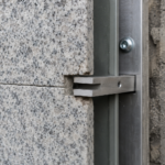
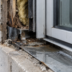
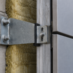
- Condensate discharging from glazing pocket weep holes onto unprotected curb substrates causes rot that standard commissioning and water testing never detect.
- A contractual gap between Division 07 and Division 08 scopes leaves the shadow zone between glazing and roofing systems owned by no one.
- Standard flashing details address bulk water intrusion but completely ignore the condensate drainage path that determines long-term curb substrate survival.
- A coordinated sill pan flashing detail showing all four control layers can prevent failure when authored before curb framing begins.
- Moisture content sensors embedded in curb framing offer a practical early-warning solution at a fraction of the cost of substrate replacement.
Sloped Glazing Curb Integration at Roof-to-Wall Transitions: Where the Perimeter Flashing Detail Fails and Why the Condensate Drainage Path Is the Structural Risk Nobody Details
Why the Roof-to-Wall Transition Is the Most Vulnerable Node in a Sloped Glazing Assembly
A post-occupancy investigation on a LEED-certified institutional library reveals soft, delaminating OSB at the base of a curtainwall-integrated skylight curb, discovered only when a roofing contractor pulls back counterflashing during a re-roofing scope two years after substantial completion. The bulk water barrier tested clean at commissioning.
The damage originated entirely from condensate draining into the glazing pocket and wicking laterally into the pressure-treated curb substrate for eighteen months. No inspection protocol flagged it because no one had detailed where the condensate was supposed to go.
That failure is not unusual. It is representative.
The sloped glazing curb assembly at a roof-to-wall transition involves at minimum six distinct components: the glazing pocket, pressure cap, thermal break, curb substrate, curb cap flashing and the primary roof membrane termination. Three or more separate trades typically install these components and no single party owns the interface between them.
The glazing contractor owns the pocket. The roofer owns the membrane termination.
The general contractor owns the curb framing. The envelope consultant coordinates but rarely authors the substrate detail.
The geometry compounds the problem. Sloped glazing intersecting a vertical or near-vertical wall plane creates a compound transition where water movement is neither purely horizontal nor purely vertical.
Standard flashing assumptions fail at this node. AAMA 2410-15 Section 4.3 defines glazing pocket drainage requirements but explicitly limits its scope to the glazing system boundary, not the curb substrate interface.
That boundary is exactly where the failure lives.
The trade sequencing problem makes the geometry problem worse. The curb framing is typically installed by the general contractor’s carpentry crew or a metal framing subcontractor working from structural drawings that show dimensions and fastener schedules but no envelope performance requirements.
The roofing contractor follows, terminating the membrane at the curb and installing counterflashing without knowing where the glazing contractor’s weep holes will discharge. The glazing contractor arrives last, sets the system into the curb and installs weep holes at locations determined by the extrusion geometry, not by the position of the counterflashing below.
By the time all three trades have completed their work, the discharge point relationship is fixed and unverifiable without destructive investigation. On a project with a compressed schedule, no party has the contractual standing or the practical opportunity to stop the sequence and force a coordination review.
The failure is built in before the glazing is even set.
The Standard Curb Flashing Detail Does One Job Well and Ignores the Other Entirely
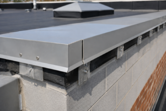
A typical envelope consultant-coordinated curb flashing detail shows membrane turn-up, counterflashing receiver, sealant joint and cap flashing. All of it is oriented toward one objective: preventing bulk precipitation from entering at the glazing-to-roof interface.
That objective is met reasonably well in most executed assemblies. The other objective, managing condensate discharge from within the glazing pocket, appears nowhere on the drawing.
What is almost never shown: the internal drainage path within the glazing pocket, the location and slope of weep holes at the sill, the relationship between the weep hole discharge point and the top of the counterflashing and the substrate material directly below that discharge point. These are not minor omissions.
They determine whether the curb substrate survives the first decade of service.
The drawing coordination failure is structural. Glazing shop drawings show weep hole locations relative to the pressure cap system.
Structural drawings show curb framing dimensions and fastener schedules. Architectural details show flashing profiles and membrane heights.
These three drawing sets are rarely overlaid during design review. The result is a “shadow zone”: the area between the bottom of the glazing pocket and the top of the roof membrane where neither the glazing system warranty nor the roofing warranty applies.
No contractor owns it. No drawing governs it.
The NRCA Roofing Manual (2023 edition) specifies membrane height minimums and IBC Section 1507 requires membrane turn-up of at least 8 inches above finished roof surface at curb conditions. Both requirements address bulk water.
Neither addresses condensate discharge coordination. The gap is not an oversight in the code; it reflects the assumption that condensate management is someone else’s scope.
On most projects, it belongs to no one.
What makes this particularly difficult to catch in design review is that the standard curb detail looks complete. A reviewer checking the architectural drawing against the IBC requirement sees the 8-inch membrane turn-up, the counterflashing receiver at the correct height and the sealant joint at the cap.
The drawing passes review. The shadow zone is not visible on that drawing because it is not drawn.
It exists in the physical assembly as the space between the bottom of the sill extrusion and the top of the counterflashing, a zone that may be one inch deep or four inches deep depending on how the glazing contractor positions the system relative to the curb face. That dimension is not shown on the architectural detail because the architectural detail was drawn before the glazing shop drawings were submitted.
By the time the shop drawings arrive, the architectural detail has already been approved and the curb has already been framed. The coordination window has closed.
Condensate in the Glazing Pocket Is Not a Comfort Problem: It Is a Structural Drainage Problem Nobody Has Assigned
In IECC Climate Zones 4 through 7, the glazing pocket at the sill of a sloped assembly is a condensation collection zone during the heating season. This is physics, not a deficiency in any particular product.
Even thermally broken systems accumulate condensate at the innermost surface of the pocket when interior dew point temperatures exceed the surface temperature of the aluminum extrusion. The thermal break reduces but does not eliminate that condition.
The intended drainage path in a properly detailed system works as follows: condensate collects at the sill, drains through weep holes in the pressure cap or sill extrusion and discharges to the exterior. In a standard curtainwall or storefront application, “exterior” means a drained cavity or a ventilated rainscreen space.
In a roof-integrated condition, “exterior” means directly onto or into the curb assembly. There is no drained cavity receiving that discharge.
There is a curb substrate.
When weep holes discharge onto an unprotected wood curb substrate or when the discharge point sits above a sealant joint that traps water rather than directing it away, the substrate absorbs moisture cyclically through each heating season. ASHRAE 160-2021 Section 5.4 addresses condensation management at fenestration assemblies and establishes the framework for evaluating this condition analytically.
Published research from Building Science Corporation identifies 19% moisture content as the rot initiation threshold for wood substrates. Pressure-treated lumber delays but does not prevent rot when subjected to sustained moisture cycling above that threshold.
The structural consequence extends beyond rot. As the curb substrate degrades, fastener pull-out resistance decreases.
The glazing system anchor points shift. The air seal at the glazing-to-curb interface opens.
What began as a condensation drainage problem converts into an air infiltration failure at the pressure boundary. Air leakage transports orders of magnitude more moisture than vapor diffusion.
Once that seal opens, the failure accelerates.
The volume of condensate involved is not trivial. A 20-foot-long sloped skylight sill in a Climate Zone 5 building with an interior relative humidity maintained at 35% during winter will generate measurable condensate accumulation on any night when the exterior temperature drops below approximately 15 degrees Fahrenheit, depending on glazing U-value and interior surface temperature.
That is not an unusual condition in Minneapolis, Chicago or Boston. Over an eighteen-month heating season cycle, the cumulative moisture discharge at the sill weeps can saturate a wood substrate that has no drainage path below it.
The glazing manufacturer’s installation manual will note that weep holes must be kept clear and unobstructed. It will not specify what material the weep discharge must land on, because the installation manual ends at the glazing system boundary.
The curb substrate is the specifier’s problem and on most projects, the specifier has not addressed it.
Steel curb construction introduces a different failure mode. Where the sill extrusion bears directly on a steel tube curb without a drainage mat or corrosion-resistant coating at fastener penetrations, the cyclic moisture from weep discharge accelerates corrosion at the anchor points.
The fastener hole becomes an elongated slot as the surrounding steel section loses section. The glazing system begins to rack.
In a sloped assembly, racking at the sill changes the drainage slope within the glazing pocket, redirecting condensate toward the jamb conditions rather than the sill weeps. The failure migrates from the sill to the jamb and the jamb-to-wall flashing detail, which was already the weakest node in the assembly, now receives concentrated moisture loading it was never designed to handle.
The Failure Hides in Plain Sight: Why Commissioning, Warranty Inspections and Water Testing All Miss Curb Substrate Degradation
AAMA 501.2 field water infiltration testing and ASTM E1105 spray rack testing apply bulk water at the exterior face and measure interior infiltration. They do not introduce water at the weep hole discharge point.
They do not assess substrate moisture content. They are the right tools for what they test and the wrong tools for this failure mode.
Building enclosure commissioning per NIBS Guideline 3 (2012) focuses on air barrier continuity testing using ASTM E779 or ASTM E1827 protocols and visual inspection of completed assemblies. Neither protocol requires destructive investigation of the curb substrate interior.
Neither requires moisture content readings at the curb framing. A commissioning agent standing on the roof during final inspection cannot see inside the glazing pocket, cannot verify weep hole discharge locations and cannot assess whether the substrate below the shadow zone is absorbing water.
Warranty inspections fare no better. The glazing manufacturer’s warranty covers the glazing system to its defined boundary.
The roofing warranty covers the membrane to its defined termination. The gap between them is unwarranted territory in the literal sense.
This is not a criticism of commissioning practice. NIBS Guideline 3 is a sound document applied to the conditions it can reasonably address.
The problem is that the profession has not yet developed a protocol for the shadow zone. Until someone specifies moisture content monitoring at curb substrates as a commissioning deliverable, this failure mode will continue to hide until a roofer pulls back counterflashing during the next re-roofing cycle.
The timeline of concealment is worth examining in detail. At substantial completion, the curb substrate is dry.
The glazing system has been installed for weeks or months, but the first heating season has not yet begun. The commissioning agent performs AAMA 501.2 testing, the assembly passes and the building is occupied.
The first heating season begins. Condensate accumulates at the sill and discharges through the weep holes onto the curb substrate.
The substrate absorbs moisture. At the end of the heating season, the substrate partially dries.
The second heating season repeats the cycle, but the substrate begins the season at a higher baseline moisture content than it did the first year. By the end of the second heating season, moisture content at the curb framing may be approaching or exceeding the 19% rot initiation threshold.
The one-year warranty inspection, which occurs before the second heating season begins, finds nothing. The two-year warranty inspection, if one is performed at all, finds nothing visible from the exterior.
The substrate is degrading inside an assembly that looks intact from every accessible vantage point. The failure only becomes visible when a roofer lifts counterflashing for an unrelated scope and finds soft framing underneath.
At that point, the glazing contractor’s warranty has expired, the roofing contractor’s warranty does not cover the substrate and the owner is holding a repair bill for damage that was predictable from the day the weep hole discharge location was left uncoordinated.
What a Correctly Detailed Condensate Drainage Path Actually Looks Like
The fix is not complicated. It requires three coordinated decisions that almost never appear on the same drawing set.
First, the weep hole discharge point must be located and shown in relation to the top of the counterflashing. If the weep discharges above the counterflashing, it needs a positive drainage path to a collection point that directs water away from the curb substrate.
A sloped sill pan flashing in stainless steel or copper, integrated with the membrane turn-up and sloped to drain to a scupper or collector, accomplishes this. The sill pan must be shown on both the architectural detail and the glazing shop drawing, with the discharge point coordinated between them.
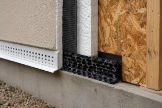
Second, the curb substrate directly below the glazing pocket sill must be protected from incidental moisture contact regardless of the primary drainage path. In wood curb construction, this means a fully adhered self-adhering membrane cap over the top of the curb framing before the glazing system is set.
In steel curb construction, it means a corrosion-resistant coating at fastener penetrations and a drainage mat or drainage board between the sill extrusion and the steel substrate.
Third, the air seal at the glazing-to-curb interface must be specified as a redundant condition, not a single-line sealant bead. A backer rod and sealant at the exterior face combined with an interior air barrier membrane termination at the curb cap gives the assembly two opportunities to maintain pressure boundary continuity as the curb substrate ages.
None of these details are exotic. All three require explicit coordination between the glazing shop drawing review and the roofing submittal review.
That coordination almost never happens without a contractual requirement forcing it.
The sill pan flashing detail deserves specific attention because it is the element most frequently omitted or incorrectly executed when it does appear. A sill pan that drains to a scupper must have sufficient slope to prevent ponding at any point along its length, which means the pan must be fabricated with a built-in slope or installed over a tapered substrate, not simply set flat and expected to drain by gravity across a long horizontal run.
A 20-foot sill pan with a 1/8-inch-per-foot slope requires 2.5 inches of elevation change from the high end to the scupper. That dimension must be accounted for in the curb framing height, the counterflashing receiver height and the glazing system sill elevation.
If the curb framing is installed at a uniform height across its length before the sill pan slope is coordinated, the glazing system sill will not be level and the pressure cap installation will be compromised. The slope must be designed into the curb framing, not added as an afterthought during glazing installation.
This is a detail that requires a single coordinated drawing showing the curb framing, the sill pan and the glazing system sill in the same section, authored before the curb is framed.
The Specification Language Gap That Enables the Problem
The root cause of most sloped glazing curb failures is not bad detailing. It is missing specification language that assigns responsibility for the shadow zone interface.
Division 08 specifications for sloped glazing systems reference AAMA 2410-15 for performance and installation requirements. Division 07 specifications for roofing reference NRCA and IBC Section 1507 for membrane termination heights.
Neither division’s specification requires the contractor to coordinate condensate discharge location with the adjacent trade’s work. The envelope consultant’s coordination drawings show the interface condition, but a drawing without a specification requirement has no contractual enforcement mechanism.
The specification fix belongs in Division 08, in the execution article, with language that requires the glazing contractor to submit weep hole locations on shop drawings for review against the roofing contractor’s counterflashing heights before fabrication is released. It also belongs in Division 07, requiring the roofing contractor to confirm that the membrane termination and counterflashing configuration accommodates the glazing contractor’s submitted weep discharge locations.
Both contractors must sign off on the coordination drawing before either scope is installed.
This is not a new concept. Curtainwall-to-roofing coordination requirements appear in well-written specifications for complex institutional projects.
The gap is that sloped glazing conditions, particularly smaller skylight curb assemblies, are frequently treated as standard curb conditions rather than the compound transitions they actually are. The result is Division 07 and Division 08 contractors who each execute their scope correctly and still produce a failure at the interface.
The specific language matters. A specification section that says “coordinate with adjacent trades” is unenforceable because it assigns no deliverable and no timeline.
A specification section that says “submit shop drawings showing weep hole discharge locations dimensioned from the top of counterflashing receiver as a condition of shop drawing approval and obtain written confirmation from the roofing contractor that counterflashing heights accommodate submitted discharge locations before releasing glazing system for fabrication” creates a specific deliverable, a specific sequence and a specific enforcement mechanism. The glazing contractor cannot release fabrication without the coordination confirmation.
The roofing contractor cannot install counterflashing without knowing the discharge location. The general contractor has a contractual basis for holding both scopes until the coordination is documented.
Division 01 can reinforce this requirement through the submittal coordination article. Listing the sloped glazing-to-roofing coordination drawing as a required submittal, distinct from the individual glazing shop drawings and roofing submittals, ensures that the coordination document is reviewed by the architect and envelope consultant before either scope proceeds.
Without that Division 01 requirement, the coordination drawing may never be produced, even if Division 07 and Division 08 both contain the language requiring it. Contractors respond to submittal requirements because submittals are tied to payment applications.
Coordination requirements that exist only in the execution article are frequently overlooked until a problem surfaces in the field.
What the Next Generation of Sloped Glazing Details Needs to Resolve
The profession is not going to stop specifying sloped glazing. Daylighting credits under LEED v4.1 and WELL Building Standard v2 are driving more skylights and more roof-integrated glazing into institutional and commercial projects in every climate zone.
The failure mode described here will scale with that volume unless the detail evolves.
The detail that needs to become standard practice is a coordinated sill section that shows all four control layers through the curb assembly in a single drawing: the water control layer (membrane turn-up, sill pan flashing and weep discharge path), the air control layer (glazing-to-curb air seal and its redundant backup), the vapor control layer (appropriate to climate zone per ASHRAE 160-2021 analysis) and the thermal control layer (thermal break continuity through the curb cap and into the roof assembly). That drawing should be authored by the envelope consultant, reviewed against glazing shop drawings before approval and made a submittal requirement in both Division 07 and Division 08.
The condensate drainage path is not a detail that can be delegated to the glazing manufacturer’s installation manual. That manual ends at the glazing system boundary.
The curb substrate is on the other side of that boundary and it is rotting.
The four-control-layer drawing format is not a new invention. Building science practitioners have used it for wall assemblies for decades and the ASHRAE 90.1 compliance path for continuous insulation at wall conditions effectively requires it.
Applying the same format to the sloped glazing curb condition is an extension of existing practice, not a departure from it. The barrier to adoption is not technical.
It is contractual and procedural. Envelope consultants who author coordination details for curtainwall-to-roof transitions on large projects already produce drawings that approach this level of coordination.
The gap is that those same consultants, working on smaller institutional projects with tighter fees and compressed schedules, frequently produce a standard curb detail that addresses the bulk water condition and leaves the condensate drainage path to be resolved in the field. The field does not resolve it.
The field installs what the drawings show and moves on.
The monitoring gap also needs a practical resolution. Specifying moisture content sensors embedded in the curb framing at the sill condition is technically feasible and commercially available.
Sensors from manufacturers serving the structural health monitoring market can be embedded in wood framing before the glazing system is set, with data loggers accessible from the roof surface. A commissioning protocol that includes a moisture content baseline reading at substantial completion, a follow-up reading at the end of the first heating season and a threshold alarm at 16% moisture content would identify a developing failure condition before it reaches the rot initiation threshold.
The cost of two sensors and a data logger at each sloped glazing curb condition is a fraction of the cost of replacing a degraded curb substrate after the glazing system has been installed over it. The specification language to require this exists in Division 01 under special inspections or in Division 08 under field quality control.
It is not being written into most project specifications because the failure mode is not yet widely recognized as predictable and preventable. That recognition is the first step.